Sames Inocoat Inocenter User manual

Instruction manual
DRT7142
B - 2023/06
Inocenter

2
Member of Exel group DRT7142
B - 2023/06
All communication or reproduction of this document, in any form whatsoever and all use or communication of its
contents are forbidden without express written authorisation from Sames.
The descriptions and characteristics mentioned in this document are subject to change without prior notice
© Sames 2021 - Translation of the original instruction manual

3
Member of Exel group DRT7142
B - 2023/06
Services
Certification and referencing
Sames is certified as a training center by the DIRRECTE of the Auvergne Rhône Alpes region under the number 84
38 06768 38.
Our company provides, throughout the year, training courses allowing you to acquire the essential know-how for the
implementation and maintenance of your equipment in order to guarantee its performance in the long term.
A catalog is available on request.
www.sames.com/france/fr/services-training.html
Line audits
As part of a technical assistance program for our customers using Sames equipment, the line audits are intended to
help you optimize and control your production tool.
Our network of experts is continuously trained and qualified to provide our customers with technical expertise on the
liquid or powder installations in which our equipment is integrated. The global environment of the production lines is
taken into account during this technical audit.
A brochure is available for download:
www.sames.com/france/fr/services-service-contract.html
Maintenance program
An annual maintenance program (including or not the consumables to be replaced during each intervention) can be
considered with the partnership of Sames. It is associated with a preventive maintenance plan established during a
first audit visit which details the control points necessary to guarantee the performance of the installed equipment.
www.sames.com/france/fr/services-service-contract.html
Hotline
www.sames.com/france/fr/services-service-contract.html

4
Member of Exel group
Inocenter
1. Health and safety instructions - - - - - - - - - - - - - - - - - - - - - - - - - - - - - - - - - - - - 6
1.1. Marking . . . . . . . . . . . . . . . . . . . . . . . . . . . . . . . . . . . . . . . . . . . . . . . . . . . . . . . . . . . . . . . . . . . . . . . . . . 6
1.2. Compliance with the ATEX directives . . . . . . . . . . . . . . . . . . . . . . . . . . . . . . . . . . . . . . . . . . . .6
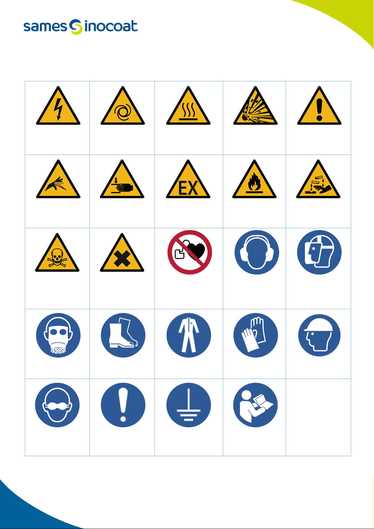
1.3. Meaning of pictograms . . . . . . . . . . . . . . . . . . . . . . . . . . . . . . . . . . . . . . . . . . . . . . . . . . . . . . . . . . . 7
1.4. Precautions for Use . . . . . . . . . . . . . . . . . . . . . . . . . . . . . . . . . . . . . . . . . . . . . . . . . . . . . . . . . . . . . . 8
1.5. Warnings . . . . . . . . . . . . . . . . . . . . . . . . . . . . . . . . . . . . . . . . . . . . . . . . . . . . . . . . . . . . . . . . . . . . . . . . . 8
1.6. Important recommendations . . . . . . . . . . . . . . . . . . . . . . . . . . . . . . . . . . . . . . . . . . . . . . . . . . . 10
1.6.1. Ventilation. . . . . . . . . . . . . . . . . . . . . . . . . . . . . . . . . . . . . . . . . . . . . . . . . . . . . . . . . . . . . . . . . . . . . . . . . 10
1.6.2. Ambient temperature . . . . . . . . . . . . . . . . . . . . . . . . . . . . . . . . . . . . . . . . . . . . . . . . . . . . . . . . . . . . . 10
1.7. Guarantee . . . . . . . . . . . . . . . . . . . . . . . . . . . . . . . . . . . . . . . . . . . . . . . . . . . . . . . . . . . . . . . . . . . . . . 11
2. Introduction - - - - - - - - - - - - - - - - - - - - - - - - - - - - - - - - - - - - - - - - - - - - - - - 12
2.1. General . . . . . . . . . . . . . . . . . . . . . . . . . . . . . . . . . . . . . . . . . . . . . . . . . . . . . . . . . . . . . . . . . . . . . . . . . 12
2.2. Equipment overview . . . . . . . . . . . . . . . . . . . . . . . . . . . . . . . . . . . . . . . . . . . . . . . . . . . . . . . . . . . 12
2.2.1. Vibrating table . . . . . . . . . . . . . . . . . . . . . . . . . . . . . . . . . . . . . . . . . . . . . . . . . . . . . . . . . . . . . . . . . . . . 12
2.2.2. Powder transfer pump . . . . . . . . . . . . . . . . . . . . . . . . . . . . . . . . . . . . . . . . . . . . . . . . . . . . . . . . . . . . 12
2.2.3. Tank . . . . . . . . . . . . . . . . . . . . . . . . . . . . . . . . . . . . . . . . . . . . . . . . . . . . . . . . . . . . . . . . . . . . . . . . . . . . . . . 12
2.3. Front view . . . . . . . . . . . . . . . . . . . . . . . . . . . . . . . . . . . . . . . . . . . . . . . . . . . . . . . . . . . . . . . . . . . . . . 13
2.4. Rear view . . . . . . . . . . . . . . . . . . . . . . . . . . . . . . . . . . . . . . . . . . . . . . . . . . . . . . . . . . . . . . . . . . . . . . 14
2.5. Operating principles . . . . . . . . . . . . . . . . . . . . . . . . . . . . . . . . . . . . . . . . . . . . . . . . . . . . . . . . . . . . 15
2.5.1. Powder equipment . . . . . . . . . . . . . . . . . . . . . . . . . . . . . . . . . . . . . . . . . . . . . . . . . . . . . . . . . . . . . . . . 15
2.5.2. New powder supply . . . . . . . . . . . . . . . . . . . . . . . . . . . . . . . . . . . . . . . . . . . . . . . . . . . . . . . . . . . . . . . 15
2.5.3. Blowing out the new powder supply . . . . . . . . . . . . . . . . . . . . . . . . . . . . . . . . . . . . . . . . . . . . . . 16
2.5.4. Recycled powder supply to tank (production phase). . . . . . . . . . . . . . . . . . . . . . . . . . . . . . 16
2.5.5. Recycled powder supply to th box powder (powder recovery phase before a
change of colour or end of production) . . . . . . . . . . . . . . . . . . . . . . . . . . . . . . . . . . . . . . . . . . . . . . . . . . 17
2.5.6. Blowing of the recycled powder supply circuit . . . . . . . . . . . . . . . . . . . . . . . . . . . . . . . . . . . . 17
2.5.7. Draining the powder tank . . . . . . . . . . . . . . . . . . . . . . . . . . . . . . . . . . . . . . . . . . . . . . . . . . . . . . . . . 18
2.5.8. Powder supply for sprayers (powder hose) . . . . . . . . . . . . . . . . . . . . . . . . . . . . . . . . . . . . . . . 18
2.5.9. Blowing out powder feed pipes for sprayers.. . . . . . . . . . . . . . . . . . . . . . . . . . . . . . . . . . . . . . 19
2.5.10. Tank blowing . . . . . . . . . . . . . . . . . . . . . . . . . . . . . . . . . . . . . . . . . . . . . . . . . . . . . . . . . . . . . . . . . . . . . 19
2.5.11. Blowing out the dense phase powder pump . . . . . . . . . . . . . . . . . . . . . . . . . . . . . . . . . . . . . 20
2.5.12. Blowing tank, pap and cyclone . . . . . . . . . . . . . . . . . . . . . . . . . . . . . . . . . . . . . . . . . . . . . . . . . . . 21
3. Characteristics - - - - - - - - - - - - - - - - - - - - - - - - - - - - - - - - - - - - - - - - - - - - - 22
3.1. Dimensions (mm) . . . . . . . . . . . . . . . . . . . . . . . . . . . . . . . . . . . . . . . . . . . . . . . . . . . . . . . . . . . . . . . 22
3.2. Characteristics . . . . . . . . . . . . . . . . . . . . . . . . . . . . . . . . . . . . . . . . . . . . . . . . . . . . . . . . . . . . . . . . . 22
3.2.1. Electrical Characteristics . . . . . . . . . . . . . . . . . . . . . . . . . . . . . . . . . . . . . . . . . . . . . . . . . . . . . . . . . . 22
3.2.2. Pneumatic characteristics . . . . . . . . . . . . . . . . . . . . . . . . . . . . . . . . . . . . . . . . . . . . . . . . . . . . . . . . . 23
3.2.3. Weight and dimensions. . . . . . . . . . . . . . . . . . . . . . . . . . . . . . . . . . . . . . . . . . . . . . . . . . . . . . . . . . . . 24
3.2.4. Dimensions of the equipment . . . . . . . . . . . . . . . . . . . . . . . . . . . . . . . . . . . . . . . . . . . . . . . . . . . . . 24
3.2.5. Handling means of the powder station . . . . . . . . . . . . . . . . . . . . . . . . . . . . . . . . . . . . . . . . . . . . 24
3.3. Noise level . . . . . . . . . . . . . . . . . . . . . . . . . . . . . . . . . . . . . . . . . . . . . . . . . . . . . . . . . . . . . . . . . . . . . 25
3.3.1. Inocenter in operation phase . . . . . . . . . . . . . . . . . . . . . . . . . . . . . . . . . . . . . . . . . . . . . . . . . . . . . . 25
3.3.2. Inocenter in cleaning phase. . . . . . . . . . . . . . . . . . . . . . . . . . . . . . . . . . . . . . . . . . . . . . . . . . . . . . . . 25
4. Starting up- - - - - - - - - - - - - - - - - - - - - - - - - - - - - - - - - - - - - - - - - - - - - - - - 26
4.1. Tools . . . . . . . . . . . . . . . . . . . . . . . . . . . . . . . . . . . . . . . . . . . . . . . . . . . . . . . . . . . . . . . . . . . . . . . . . . . 26

5
Member of Exel group
4.2. Installation . . . . . . . . . . . . . . . . . . . . . . . . . . . . . . . . . . . . . . . . . . . . . . . . . . . . . . . . . . . . . . . . . . . . . 26
4.2.1. Electrical connections Inocenter - control cabinet . . . . . . . . . . . . . . . . . . . . . . . . . . . . . . . . 26
4.2.2. Pneumatic connections Inocenter - control cabinet . . . . . . . . . . . . . . . . . . . . . . . . . . . . . . . 26
4.2.3. Raccordement de la gaine de ventilation . . . . . . . . . . . . . . . . . . . . . . . . . . . . . . . . . . . . . . . . . . 27
4.2.4. Vibrrating table. . . . . . . . . . . . . . . . . . . . . . . . . . . . . . . . . . . . . . . . . . . . . . . . . . . . . . . . . . . . . . . . . . . . 27
4.2.5. Ground connection . . . . . . . . . . . . . . . . . . . . . . . . . . . . . . . . . . . . . . . . . . . . . . . . . . . . . . . . . . . . . . . . 27
4.2.6. Sensitivity adjustment of powder level sensors . . . . . . . . . . . . . . . . . . . . . . . . . . . . . . . . . . . 27
4.2.7. Setting the air regulators. . . . . . . . . . . . . . . . . . . . . . . . . . . . . . . . . . . . . . . . . . . . . . . . . . . . . . . . . . 28
4.2.8. Level sensor fluidization air setting . . . . . . . . . . . . . . . . . . . . . . . . . . . . . . . . . . . . . . . . . . . . . . . 28
4.2.9. Installation of solenoid valves for booth floor blower (option) . . . . . . . . . . . . . . . . . . . . 28
4.2.10. Installation of external powder supply (option). . . . . . . . . . . . . . . . . . . . . . . . . . . . . . . . . . 29
5. Maintenance - - - - - - - - - - - - - - - - - - - - - - - - - - - - - - - - - - - - - - - - - - - - - - 31
5.1. Maintenance summary table . . . . . . . . . . . . . . . . . . . . . . . . . . . . . . . . . . . . . . . . . . . . . . . . . . . 31
5.2. Cleaning . . . . . . . . . . . . . . . . . . . . . . . . . . . . . . . . . . . . . . . . . . . . . . . . . . . . . . . . . . . . . . . . . . . . . . . . 32
5.2.1. Procedure A1: Checking the condition of the powder pumps. . . . . . . . . . . . . . . . . . . . . . 32
5.2.2. Procedure A2: Checking the condition of the tank lid seal . . . . . . . . . . . . . . . . . . . . . . . . . 32
5.2.3. Procedure A3: Checking the condition of the sleeve valves . . . . . . . . . . . . . . . . . . . . . . . 32
5.3. Replacement . . . . . . . . . . . . . . . . . . . . . . . . . . . . . . . . . . . . . . . . . . . . . . . . . . . . . . . . . . . . . . . . . . . 32
5.3.1. Procedure B1: Replacement of the vacuum generator. . . . . . . . . . . . . . . . . . . . . . . . . . . . . 32
5.3.2. Procedure C1: Replacement of a powder pump . . . . . . . . . . . . . . . . . . . . . . . . . . . . . . . . . . . 32
5.3.3. Procedure C2: Replacement of the ejector, injector, porous tube and sleeve valve
of the powder pump . . . . . . . . . . . . . . . . . . . . . . . . . . . . . . . . . . . . . . . . . . . . . . . . . . . . . . . . . . . . . . . . . . . . . 33
5.3.4. Procedure D1: Replacement of the porous plate and flat seal on the tank bottom 34
6. Trouble shootings - - - - - - - - - - - - - - - - - - - - - - - - - - - - - - - - - - - - - - - - - - - 36
7. Spare part list - - - - - - - - - - - - - - - - - - - - - - - - - - - - - - - - - - - - - - - - - - - - - - 37
7.1. Inocenter Powder Station . . . . . . . . . . . . . . . . . . . . . . . . . . . . . . . . . . . . . . . . . . . . . . . . . . . . . . 38
7.1.1. Control and blower terminal boards . . . . . . . . . . . . . . . . . . . . . . . . . . . . . . . . . . . . . . . . . . . . . . . 40
7.1.2. Transfer pump management board . . . . . . . . . . . . . . . . . . . . . . . . . . . . . . . . . . . . . . . . . . . . . . . . 41
7.1.3. Ventilation duct assembly . . . . . . . . . . . . . . . . . . . . . . . . . . . . . . . . . . . . . . . . . . . . . . . . . . . . . . . . . 42
7.1.4. Recycling and new powder sleeve valve assemblies . . . . . . . . . . . . . . . . . . . . . . . . . . . . . . 43
7.1.5. Set of solenoid valves for cleaning and blowing out . . . . . . . . . . . . . . . . . . . . . . . . . . . . . . . 44
7.1.6. Vibrating tables . . . . . . . . . . . . . . . . . . . . . . . . . . . . . . . . . . . . . . . . . . . . . . . . . . . . . . . . . . . . . . . . . . . 45
7.1.7. Tank . . . . . . . . . . . . . . . . . . . . . . . . . . . . . . . . . . . . . . . . . . . . . . . . . . . . . . . . . . . . . . . . . . . . . . . . . . . . . . . 47
7.1.8. Powder Pump assembly . . . . . . . . . . . . . . . . . . . . . . . . . . . . . . . . . . . . . . . . . . . . . . . . . . . . . . . . . . . 50
7.1.9. External powder supply (option) . . . . . . . . . . . . . . . . . . . . . . . . . . . . . . . . . . . . . . . . . . . . . . . . . . 51
8. Revision index History - - - - - - - - - - - - - - - - - - - - - - - - - - - - - - - - - - - - - - - - 52
9. Appendices - - - - - - - - - - - - - - - - - - - - - - - - - - - - - - - - - - - - - - - - - - - - - - - 53
9.1. EU and UK Declarations of conformity . . . . . . . . . . . . . . . . . . . . . . . . . . . . . . . . . . . . . . . . . . 53

6
Member of Exel group DRT7142
B - 2023/06
1. Health and safety instructions
This manual contains links to the following instructions manuals:
•see DRT6454 for Inotransfer.
•see DRT6457 for Inomaster Platinum.
1.1. Marking
The Inocenter is intended for use out of an explosive atmosphere.
1.2. Compliance with the ATEX directives
According to Directives 1999/92/EC and Dangerous Substances and Explosive Atmospheres Regulations 2002,
the responsibility for defining ATEX zones lies with the user. In accordance with the EN 16985 Standard, Sames
has designed the Inocenter considering the following zones:
• Zone 20 for the inner volume of the powder fluidized tank.
• Zone 22 for the inner volume of the enclosure and the evacuation sheath.
DES08062
DES08059
Zone 22
Zone 20

7
Member of Exel group DRT7142
B - 2023/06
1.3. Meaning of pictograms
Warning
electricity
Warning
Automatic start-up
Warning
Hot surface
Warning
Explosive material
General warning
sign
Warning
High pressure
Warning
Crushing of hands
Warning for
explosive
atmospheres
Warning
Flammable
material
Warning
Corrosive
subtance
Warning
Toxic material
Warning
Harmful products
No access for
people with active
implanted cardiac
devices
Wear ear
protection
Wear a face
shield
Wear respiratory
protection
Wear safety
footwear
Wear protective
clothing
Wear protective
gloves
Wear head
protection
Opaque eye
protection must
be worn
General mandatory
action sign
Connect an
earth terminal
to the ground
Refer to
Instruction manual

8
Member of Exel group DRT7142
B - 2023/06
1.4. Precautions for Use
This document contains information that all operators should be aware of and understand before using the
Inocenter. This information highlights situations that could result in serious damage and indicates the precautions
that should be taken to avoid them.
Before any use of the Inobox control module, check that all operators:
• have previously be trained by the company Sames, or by their distributors registered by them for this
purpose.
• have read and understood the user manual and all rules for installation and operation, as laid out
below.
It is the responsibility of the operators’ workshop manager to ensure these two points and it
is also his responsibility to make sure that all operators have read and understood the user
manuals for any peripheral electrical equipment present in the powdering area.
1.5. Warnings
It is imperative that anyone wearing a pacemaker does not use the equipment and does not
enter the projection area.
High voltage can cause the pacemaker to malfunction.
This equipment may be hazardous if it is not used, disassembled and reassembled in
accordance with the rules indicated in this manual and in any applicable European Standard or
national safety regulations.
Equipment performance is only guaranteed if original spare parts distributed by Sames
are used.
During the cleaning cycle of the powder station, it is imperative to block the powder plunger
on its support.
This equipment should only be used outside of an explosive atmosphere. The equipment
should only be used in a well-ventilated area to reduce health, fire and explosion hazards. The
effectiveness of the exhaust ventilation system should be checked daily.

9
Member of Exel group DRT7142
B - 2023/06
1 The operator must wear shoes according to standard EN ISO 20344 and the insulation resistance measured
must not exceed 100 MΩ.
2 The protective clothes, including gloves, must conform to standard EN 1149-5 and the insulation resistance
measured must not exceed 100 MΩ.
3 Make sure that the pneumatic pressure inside is completely exhausted before adjusting or servicing
pressurized systems or parts.
4 Using individual protection equipment will limit the risks of contact and/or inhalation of toxic product, gas,
vapours, fog or dusts that can be produced while using the equipment. The user has to follow the coating
product manufacturer’s recommendations.
5 Appropriate measures must be taken to prevent potential energy being present in the equipment during
periods of non-use and/or when the equipment is out of service.
6TheInocenter powder station must be maintained regularly in accordance with the indications and instructions
given by Sames. Repairs must be carried out in strict accordance with these instructions.
7 Unplug, lock out and turn off electrical equipment before servicing electrical equipment.
8 Turn off all electrical or electrostatic equipment immediately, even if the operator is exposed to a slight electric
shock. Do not restart the equipment until the problem has been diagnosed and resolved.
9 The powder station, especially the vibrating table and all conductive structures placed in or near the work place
must be electrically connected to the protective grounding system of the power supply.
10All grinding or welding work on metal products carried out at a distance of less than 5 meters from the powder
station is prohibited if the following safety measures are not observed
• The powder station must be protected by a cover made of non-flammable (or hardly flammable) material.
• A person equipped with a fire extinguisher must monitor the environment of the powder station during the
work.
11The powder station must not support a mass other than that of the equipment originally intended to be
mounted on or around it. The structure of the powder station is self-supporting. In no case is the powder station
designed to support the mass of an operator working on its roof, the mass of a part of the building or any other
load.
12The floor on which the power plant is installed must have a strength of more than 400 kN/m2.
13 Do not bring corrosive products or objects likely to deteriorate its surface into contact with the powder station.

10
Member of Exel group DRT7142
B - 2023/06
1.6. Important recommendations
1.6.1. Ventilation
Do not start the powder application with the Inocenter until the ventilation system of the spray booth is switched
on. If the ventilation is turned off, toxic substances or dust may remain in the spray booth and cause a risk of fire,
poisoning or irritation.
1.6.2. Ambient temperature
The Inocenter powder station is designed to normally operate at an ambient temperature comprised between 0°C
and + 40°C.
The storage temperature must never exceed +60°C.
This powder distribution plant Inocenter is usually connected to a filter unit via a ventilation
duct.
A filter explosion protection system in accordance with the ATEX Directive 2014/34/EU is
required.
Sames recommends to install a spark detector in the enclosure of the power station
connected to a CO2 injection system in the ventilation duct.

11
Member of Exel group DRT7142
B - 2023/06
1.7. Guarantee
Under the guarantee, which applies only to the buyer, Sames agrees to repair operating faults resulting from a
design fault, materials or manufacture, under the conditions set out below.
The guarantee claim must define the exact nature of the fault concerned, in writing.
The Sames guarantee only covers equipment that has been serviced and cleaned according to standard procedures
and our own instructions, that has been fitted with parts approved by Sames or that has not been modified by the
customer.
More precisely, the guarantee does not cover damage resulting from:
• the customer's negligence or inattention,
• incorrect use,
• failure to follow procedures,
• use of a control system not designed by Sames or a Sames control system modified by a third party without
written permission from an authorized Sames technical agent,
• accidents such as: collision with external objects, or similar events,
• flooding, earthquake, fire or similar events,
• the use of seals that do not comply with those recommended by Sames,
• pollution of pneumatic circuits by fluids or substances other than air.
The Sames Inocenter equipment is covered by a warranty (refer to the general sales conditions for its application).
The guarantee does not apply to wearing parts.
The guarantee will take effect from the date of the first start-up or of the provisional acceptance report.
Under no circumstances, either in the context of this guarantee or in other contexts, will Sames be held responsible
for physical injury or intangible damage, damage to brand image and loss of production resulting directly from its
products.

12
Member of Exel group DRT7142
B - 2023/06
2. Introduction
2.1. General
The Inocenter powder station is a ventilated powder dispensing enclosure allowing:
1 Powder supply to projectors and guns (24 maximum).
2 Automatic cleaning of:
•powderpumps,
• powder supply hoses,
• the inside of projectors and guns,
• powder recycling hose.
• powder tank.
The powder station can operate autonomously.
It is then controlled from the keyboard located on the front of the electro-pneumatic cabinet (see DRT6457 for the
Inomaster Platinum cabinet). The PLC monitor allows the operator to be guided and to follow his actions in real time.
It indicates to the operator the status of the powder unit (defects, cleaning steps, operations to be carried out).
2.2. Equipment overview
2.2.1. Vibrating table
The table, a 20kg powder box support, is equipped with an electric vibrator to facilitate the flow of the powder during
the pumping phase.
During the cleaning phase, the table, which is mobile, must be moved manually under the tank drain valve in order to
empty it.
Once cleaning is completed, return the table to its initial position.
When you have finished cleaning, return the table to its original position.
2.2.2. Powder transfer pump
This pump, equipped with 4 sleeves, allows the transport of new powder from the box to the fluidized tank.
During the production phase, the operation of the pump is managed by the level sensors of the tank.
The transport capacity of this pump, with a new powder box, is around 300 kg/min.
When starting the installation, it is necessary to force the filling of the tank until the information: "central OK" is
obtained.
2.2.3. Tank
This fluidized tank allows the distribution of powder to the projectors through a set composed of a sleeve valve and
a venturi type pump.
This tank can be equipped with a maximum of 24 pumps. It is equipped with 2 powder level detectors to ensure the
management of the filling and to maintain a constant level during the production phase.
An electric vibrator guarantees a good fluidization for difficult powders.
The tank is connected directly to the ventilation duct via a valve mounted on a pneumatic cylinder. This flap allows
to significantly increase the suction flow when it is open during the cleaning phases.
The tank must be emptied every evening at the end of the shift.

13
Member of Exel group DRT7142
B - 2023/06
2.3. Front view
Element Function
Emergency stop push-button Located on the control cabinet
Bulkhead feed-through plates Plates equipped with bulkhead bushings and cable glands allowing the
passage of cables and hoses on the bottom of the power plant.
Powder tank Powder tank equipped with maximum 24 powder pumps
Compressed air blower Allows the cleaning of the powder station
Vibrating table Moving support of the powder box
New powder supply plunger New powder suction rod
Plunger support Quick plunger locking system in cleaning position
Powder level sensors Indicate high and low levels of powder in the tank
Connection for cleaning hopper under cyclone Evacuation of cleaning hopper under cyclone
Compressed air
blower
Powder tank
Bulkhead
feed-through
plates
Vibrating table
Plunger
support
New powder
supply plunger
Connection for
cleaning hopper
under cyclone
Powder level sensors

14
Member of Exel group DRT7142
B - 2023/06
2.4. Rear view
Element Function
Lighting LED Indoor Lighting of Powder station
Frame Structure of the powder station
Ventilation duct assembly Ducting of the suction air to the filter unit (operation and clean-
ing)
Transfer pump control board Controls the transfer pump
Inotransfer pump Supplies the plant with new powder
New powder supply sleeve valves New powder supply circuit management valves
Grounding Bars Grounding Cable Connectors
Powder recycling sleeve valves Powder recycling circuit management valves
Suction guillotine Controls the suction air to the filter unit during operation or
cleaning
Solenoid valves for blowing out the tank Allow cleaning of the tank
Inobooth floor blowing solenoid valves (optional) Clean the Inobooth floor
Air tank equipped with solenoid valves for cleaning and
blowing Used for cleaning the distribution and recycling cycles
Distribution terminal board, sleeve valve and blowing
management
All the distribution terminals which allow the control, the man-
agement of the sleeve valves and the blowing.
Roof plates for distribution management
Plates equipped with bulkhead bushings and cable glands allow-
ing the passage of cables and pipes on the top of the power
plant.
Inotransfer pump
Transfer pump
control board
New powder supply
sleeve valves
Air tank equipped
with solenoid valves
for cleaning and
blowing
Ventilation duct
assembly
Solenoid valves for
blowing out the tank
Frame
Powder recycling
sleeve valves
Suction guillotine
Roof plates for
distribution
Lighting
Grounding Bars
Distribution terminal
board, sleeve valve and
blowing management
Electrovannes de
soufflage du plancher
de l’Inobooth

15
Member of Exel group DRT7142
B - 2023/06
2.5. Operating principles
2.5.1. Powder equipment
The Inocenter powder unit is part of the Sames powder range.
2.5.2. New powder supply
The supply of new powder starts when the tank is filled for the first time, and in the production phase when the high
level sensor is lost, followed by an adjustable delay. The pump transfers the powder from the container to the tank.
Sleeve valve QR11 open and sleeve valve QR23 closed.
DES09280
KK511 KK523
QR23
QR11
KK23
N225
Powder tank
Air tank
Powder
pump
Powder
box Powder flow

16
Member of Exel group DRT7142
B - 2023/06
2.5.3. Blowing out the new powder supply
During a color change or when emptying the tank, the supply lines for new powder are blown by air streams to ensure
effective cleaning.
The air streams are sent successively to the suction pipe and to the tank.
2.5.4. Recycled powder supply to tank (production phase)
The recycled powder comes from the bottom of the cyclone or is then transported by the flip flop system of the
sleeve valves to the tank. Recycling of the powder starts when the high level sensor in the tank + tempo is lost. Airs
T21A and T22A are transport airs to evacuate the powder to the tank.
DES09281
KK511 KK523
QR23
QR11
KK23
N225
Powder tank
Air tank
Powder
box Air flow
Powder
pump
DES09282
KK24
KK548 KK510 KK524
QR48
QR24
QR10
N225 EVM22
Air T21A
Air T22A
EVM21
Powder
tank
Air tank
Evacuation
smoke
ventilation
Powder
box Powder flow
Evacuation to
ventilation
Manual connection
(quick connector)
ventilation or recycling

17
Member of Exel group DRT7142
B - 2023/06
2.5.5. Recycled powder supply to th box powder (powder recovery phase before a change of colour
or end of production)
During a colour change or at the end of production with recovery of work in progress. The recycled powder coming
from the bottom of the cyclone is transported by the flip flop system of the sleeve valves to the powder box. Airs
T21A and T22A are transport airs to evacuate the powder to the tank. The sleeve valves QR10 and QR24 are closed.
2.5.6. Blowing of the recycled powder supply circuit
The powder ducts are cleaned alternately from the air tank to the tank (EVM21 and QR 48 closed), from the air tank
to the ventilation (QR10&EVM21 closed), from the air tank to the cyclone (QR10&QR48 closed).
DES09283
KK24
KK548 KK510 KK524
QR48
QR24
QR10
N225 EVM22
Air T21A
Air T22A
EVM21
Powder
tank
Air tank
Evacuation
smoke
ventilation
Powder
box Powder flow
Manual connection
(quick connector)
ventilation or recycling
DES09284
KK24
KK548 KK510 KK524
QR48
QR24
QR10
N225 EVM22
Air T21A
Air T22A
EVM21
Powder
tank
Air tank
Evacuation
smoke
ventilation
Powder
box Air flow
Evacuation to
ventilation
Manual connection
(quick connector)
ventilation or recycling

18
Member of Exel group DRT7142
B - 2023/06
2.5.7. Draining the powder tank
The tank is emptied when the colour is changed or when production is completed.
2.5.8. Powder supply for sprayers (powder hose)
The powder supply to the projectors is managed by the venturi pump. The injection air acts on the powder flow
and the dilution air on the transport air to bring the air/powder mixture to the projector in a homogeneous manner.
DES09285
QR11
Powder
tank
Powder
box
Powder flow
Tank drain valve
DES09286
QRPL01...12
QRPR01...12
KK20L01...L12
KK20R01...R12
Powder
tank
Powder flow
Up to 24 projectors
Injection air
Dilution air
Venturi pump

19
Member of Exel group DRT7142
B - 2023/06
2.5.9. Blowing out powder feed pipes for sprayers.
The powder hoses of the sprayers are blown by two air supply sources.
1 By controlling the injection and dilution valves at maximum setting (once the powder tank has been emptied).
2 By alternately ordering KK20 valves L01... LXX. Air streams are sent to the sprayers and to the tank when the
QRPLXX sleeve valves for the air streams are opened.
2.5.10. Tank blowing
The tank has its own air supply via two air inlets on the rear panel. Valves QR45 and QR44 are closed during cleaning
air trains. The tank is also cleaned by the new and recycled powder supply pipes during the cleaning phases.
DES09287
QRPL01...12
QRPR01...12
KK20L01...L12
KK20R01...R12
Powder
tank
Air flow
Up to 24 projectors
Injection air
Dilution air
Blowing air
Venturi pump
DES09288
KK548 KK548
KK225KK224
QR44
QR45
Powder
tank
Air flow
Evacuation to
ventilation
Tank supply
distributorr

20
Member of Exel group DRT7142
B - 2023/06
2.5.11. Blowing out the dense phase powder pump
The powder pump is blown by several air supply sources:
1 Via the KK9 valve, which sends trains of air at network pressure through the porous filters
1 filters of the pump to clean them and evacuate the powder into the ventilation system through the draw pipe.
2 Valves QR 23 and KK 23 send air streams to the pump's chambers A&B (depending on the opening of valves
PV1...PV4).
DES09289
KK23
KK523
KK8KK7
KK5KK6
KK9
PV2
CHBCHA
PV4
PV1
PV3
QR23
QR11
N225
KH24
KKCHA
KKCHB
Powder
tank
Air network Air flow
Aspiration/blowing
Aspiration/blowing
Evacuation
to ventilation
Powder supply
plunger in its housing
along the
powerstation
Air tank
Vacuum
generator
Regulator
RQ see in cycle if
QR11 is still closed
Table of contents
Other Sames Industrial Equipment manuals