manuals.online logo
Brands
  1. Home
  2. •
  3. Brands
  4. •
  5. lancer
  6. •
  7. Industrial Equipment
  8. •
  9. lancer BEV85 User manual

lancer BEV85 User manual

www.lancerbeverage.com Page 1 of 4
Images are for illustration purposes only as product may vary. No 074 –1 November 2018
BEV85 Annual Operational Service
Work Instruction
Why
Annual Operational Service –Filters, Non Return Valve & Compressor Head
Time required
40-60 minutes to complete
Hazard icons
Tools and supplies
PH2
5mm
Videos are available to support this
equipment from Hoshizaki Lancer. Please
see…
www.lancerbeverage.com
Overview:
https://youtu.be/-pKwifqzQEY
Troubleshooting:
https://youtu.be/OobMs8csyj0
Service:
https://youtu.be/_jS9Mm8xmXQ
Safety Glasses
Paper Towel
Gloves
Tools
- PH2 Screw Driver
- Adjustable Spanner
- 5mm Allen Key
Cleaning
alcohol
Soapy water
Annual Service Kit
#80000204
Loctite® 222
Procedure
1
Change Over to CO2 supply
Switch main Beverage Control
Panel over to back-up CO2
supply.
2
Isolate Air Compressor –
Electrical
Press the red button on the
pressure switch to turn off the
compressor.
Isolate and disconnect the
electrical lead from the wall
socket.
3
Isolate Air Compressor –
Air Supply
Turn the supply air tap off, ¼
turn. The red handle will be 90
degrees to the hose when off.
4
Drain air tank
Drain the air tank through the
Drain Cock on the base of the
receiver tank.
Turn Clockwise, slowly loosen
Drain Cock to release
compressed air.
Monitor for excessive
moisture draining from the
tank.
Compressed air use of Gloves
& safety glasses is required.
Replace Tank Drain Cock
Wipe drain cock clean.
Refit drain cock, turning anti-
clockwise, ensure finger tight
fitment.
5
Inspect and Drain Regulator
Filter bowl.
Check the condition of the
condensation bowl at the base
of the Filter Regulator.
If dirty and more than 10 mm
of moisture present remove &
Clean.
BEV85 Annual Operational Service
Work Instruction
www.lancerbeverage.com Page 2 of 4
Images are for illustration purposes only as product may vary. No 074 –1 November 2018
5
Remove Regulator Filter
Bowl
Turn Clockwise and pull down
to remove.
Clean with warm soapy water.
Take a photo or placement
and orientation
Remove Regulator Brass
Filter
Turn the Brass Cartridge
Clockwise to loosen and
remove.
Clean with warm soapy water.
Clean by placing in sanitiser
alcohol to soak and shake.
Refit by turning anti-clockwise
once cleaned or replaced.
Replace Regulator Filter
Bowl
Push up and turn anti-
clockwise to replace bowl.
6
Access Air filters (2 of)
Twist anti-clockwise and pull
on the filter casing cap to
expose the filter element
inside.
Clean air filter housings
Wipe clean the filter housing
and cap.
Replace air filter & Cap
Fit two new air filter elements,
as available in annual service
kit.
Locate filter cap onto the
housing and twist clockwise to
replace and lock into place.
7
Replace the Non-Return
Valve (NRV) Seal & Spring
With the use of a Spanner,
turn the nut anti-clockwise to
loosen.
Remove and dispose of the
spring & seal.
Note orientation of parts as
removing them.
Fit the new Seal & Spring, as
available in the annual service
kit, and replace the NRV nut.
Tighten using only fingers, in
a Clockwise direction.
8
Remove compressor head
Heat Covers
Remove the 4 fixing screws
securing the 2 heat covers.
PH2 Phillips heads.
BEV85 Annual Operational Service
Work Instruction
www.lancerbeverage.com Page 3 of 4
Images are for illustration purposes only as product may vary. No 074 –1 November 2018
9
Disconnect High Pressure
Hose
Using a Spanner, Turn
Clockwise to loosen hose
fitting.
Disconnect the hose from
brass elbow attached to the
compressor head.
10
Loosen all 12 Head bolts
Use a 5mm Alan key
Turn Anti-clockwise to loosen.
Leave the bolts in place.
11
Remove cylinder head
Lift remove cylinder head
assembly, as one whole
piece.
12
Remove valve plates
Remove both valve plates,
note orientation before
removal.
Take a photo or placement
and orientation
13
Remove adjuster holders
14
Remove both piston barrels
Remove and dispose of both
piston barrels.
15
Remove & Replace both
piston rings
Use a 5mm Alan Key
Turn Anti-clockwise to loosen
piston plate fixing screw.
Remove piston top plate and
separate ring. Dispose of the
ring.
Use a new ring from the
Service kit and refit to the
piston plate and piston.
Apply a small portion of
Loctite® (222) to fixing screw
thread.
16
Replace both piston barrels
Take care to with piston ring
when fitting the new barrel.
Piston Barrel is supplied with
Annual service kit.
Sometimes it is necessary to
first fit piston barrel then fit
ring/piston top plate.
17
Replace both Adjuster
holders
18
Replace both head plates
Note orientation when
refitting.
Valve plate screw and Piston
Plate indent need to align.
BEV85 Annual Operational Service
Work Instruction
www.lancerbeverage.com Page 4 of 4
Images are for illustration purposes only as product may vary. No 074 –1 November 2018
19
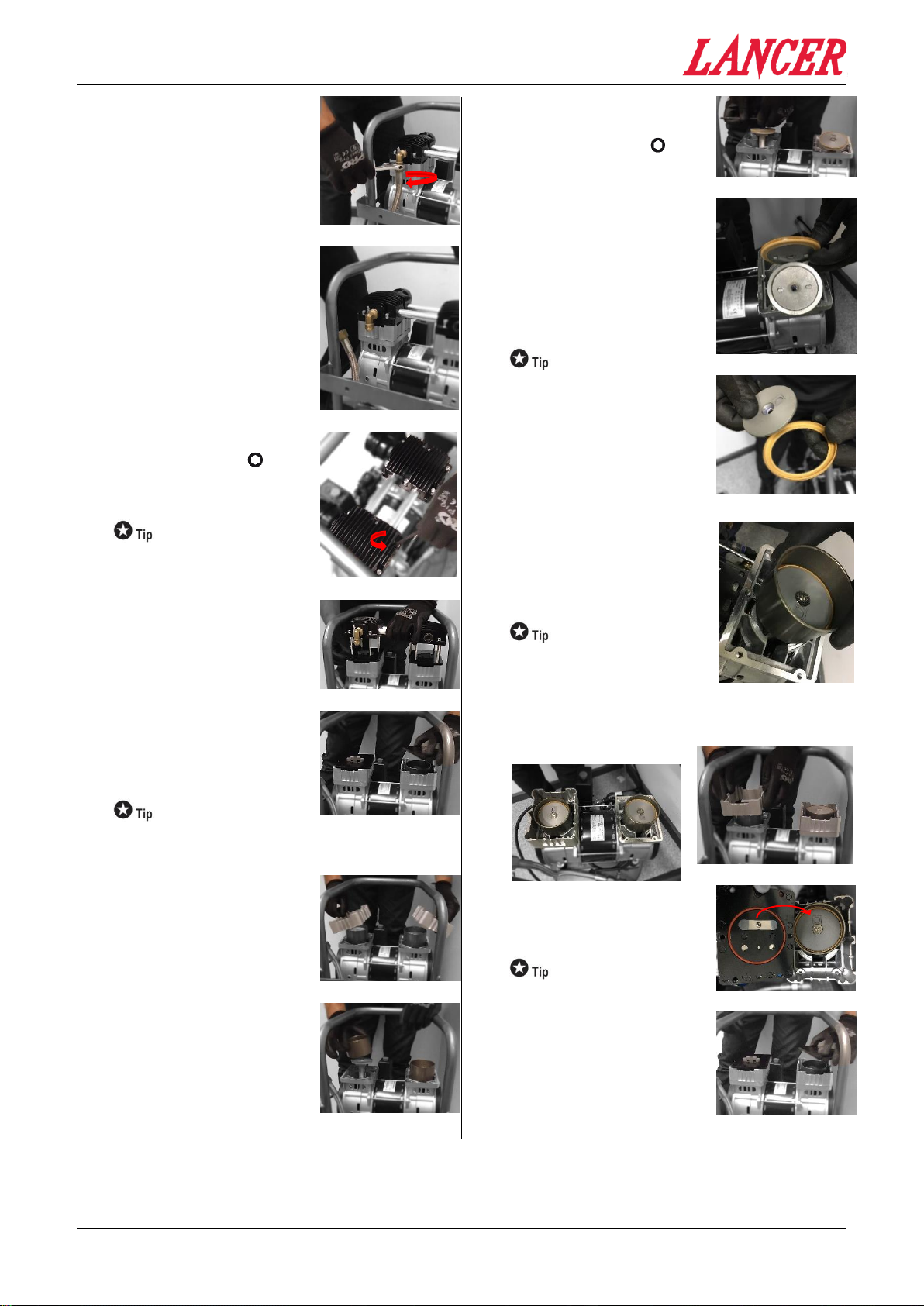
Replace cylinder head
assembly
20
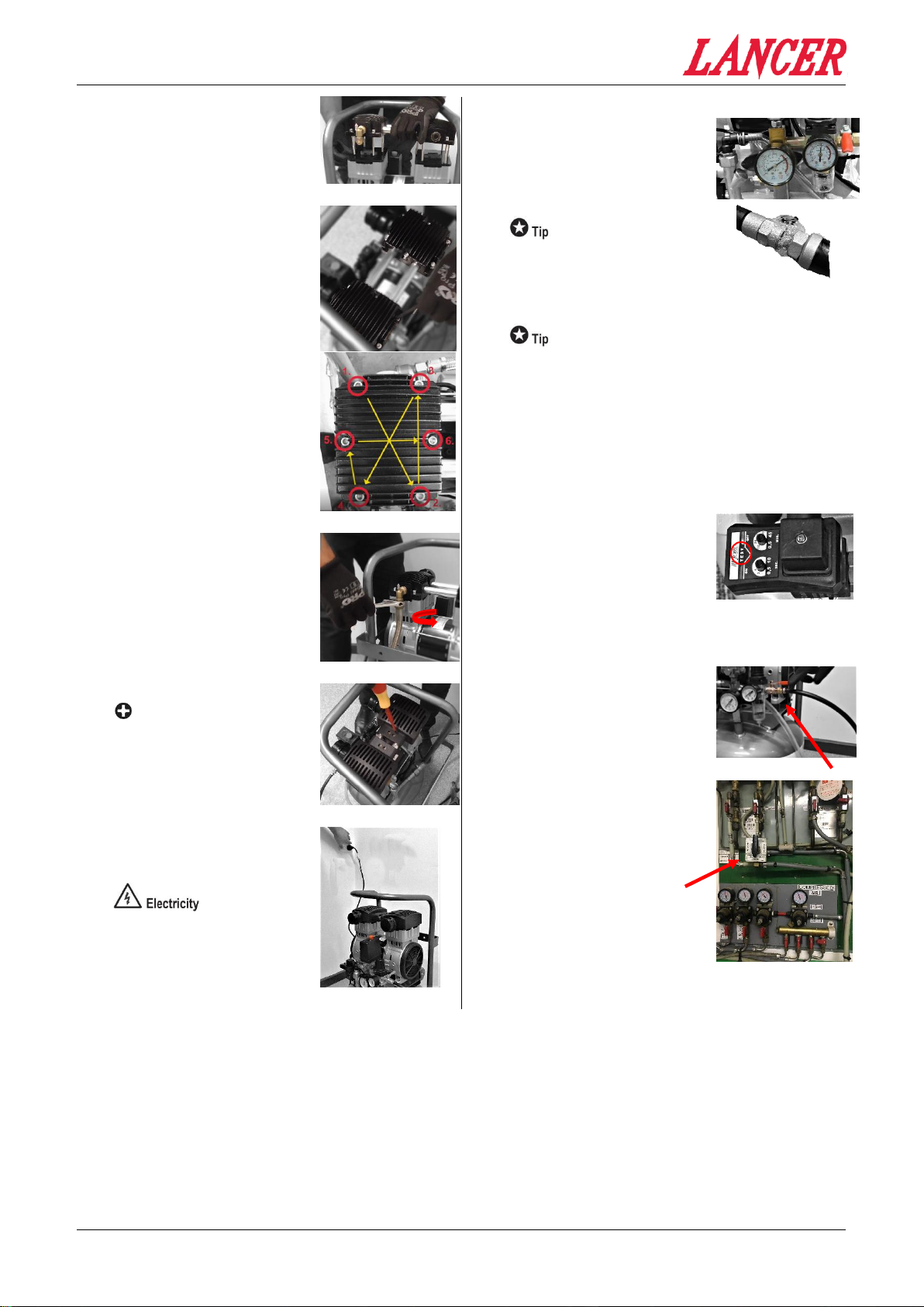
Tighten all 12 head bolts
Follow tensioning pattern
Hand tighten each bolt,
clockwise, extra leverage is
not required.
Each bolt has a spring
washer, fitted to assist with
securing the fixing.
Aluminum threads strip easily.
21
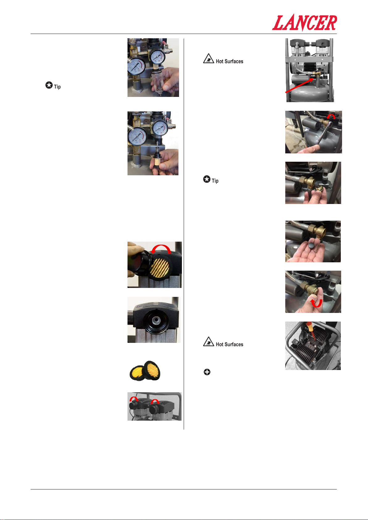
Connect High Pressure
hose
Using a Spanner, Turn anti-
Clockwise to tighten hose
fitting.
22
Replace heat covers
PH2 Phillips heads
2 x heat covers
Replace heat covers, secure
each with 2 fixing screws.
23
Re-connect and energise
the electrical supply to the
air compressor
Plug electrical lead into socket
outlet and lift red button on
pressure switch to turn on the
air compressor.
24
Check for air leaks
Monitor the tank pressure
gauge, listen for leaking air
(hissing) and/or use soapy
water to inspect air fittings,
pipe joints & connections.
Compressor will run for about
1 minute 30 second before
cycling off.
Check the NRV Operation
When the compressor
reaches its cut-out pressure
there should be a shot of air
from underneath the pressure
switch. If this shot of air is not
evident or the air continually
leaks replace the Non-Return
Valve Seal & Spring.
25
Test auto-drain
Press the “TEST” button on
the Auto Drain which should
release a burst of air and then
stop.
If this does not work have the
compressor checked by an
approved service agent.
26
Re-connect air supply
Turn the supply air tap on, ¼
turn. Handle will be in line with
the hose.
This is the red handle.
27
Change Over to
Compressed Air supply
Switch main Beverage Control
Panel over to Compressed air
supply from CO2 supply.

Other lancer Industrial Equipment manuals

lancer BEV85 User manual

lancer

lancer BEV85 User manual

lancer 2300 Series User manual

lancer

lancer 2300 Series User manual

Popular Industrial Equipment manuals by other brands

Logosol B1001 user manual

Logosol

Logosol B1001 user manual

ABB HT613219 Operation manual

ABB

ABB HT613219 Operation manual

ABB HT845174 Operation manual

ABB

ABB HT845174 Operation manual

Siemens 3TL61 operating instructions

Siemens

Siemens 3TL61 operating instructions

PIAB KCS Series Assembly manual

PIAB

PIAB KCS Series Assembly manual

Delem DA-65W Reference manual

Delem

Delem DA-65W Reference manual

ProMinent Chlorinsitu-III Assembly and operating instructions

ProMinent

ProMinent Chlorinsitu-III Assembly and operating instructions

Hainbuch hs dock operating instructions

Hainbuch

Hainbuch hs dock operating instructions

ABB HT610533 Operation manual

ABB

ABB HT610533 Operation manual

BlastPro BP-505 Machine manual

BlastPro

BlastPro BP-505 Machine manual

Kval 994-X Operation and service manual

Kval

Kval 994-X Operation and service manual

Loctite Zeta 7215 Operation manual

Loctite

Loctite Zeta 7215 Operation manual

Schmalz FMP-SVK Series operating instructions

Schmalz

Schmalz FMP-SVK Series operating instructions

Innotech INNOTECH BEF 401-10 Instructions for installation and use

Innotech

Innotech INNOTECH BEF 401-10 Instructions for installation and use

StorCase Technology Data Silo DS321 user manual

StorCase Technology

StorCase Technology Data Silo DS321 user manual

IPG Photonics LC 340.01-A.3.5/6 operating manual

IPG Photonics

IPG Photonics LC 340.01-A.3.5/6 operating manual

Trane BACnet BCI-I installation guide

Trane

Trane BACnet BCI-I installation guide

SAINT-GOBAIN VISION-LITE Guidelines

SAINT-GOBAIN

SAINT-GOBAIN VISION-LITE Guidelines

manuals.online logo
manuals.online logoBrands
  • About & Mission
  • Contact us
  • Privacy Policy
  • Terms and Conditions

Copyright 2025 Manuals.Online. All Rights Reserved.