Langmatz VarioPipe User manual

Installation Instructions
- VarioPipe optical fibre building cable & pipe entry system;
- VarioPipe optical fibre building cable & pipe entry system
with adapter for cartridge gun;
For wall thicknesses from 200 mm;
For Core drill hole ø 25 mm;
For media cables:
1x copper or optical fibre cable ø 6-13 mm
1x SpeedNet pipe ø 7-12 mm
1x oval cable 4/8 mm
2x micropipes ø 7 mm

2
Contents
english
1General information .....................................................................................................3
2Safety information........................................................................................................3
3Product description......................................................................................................4
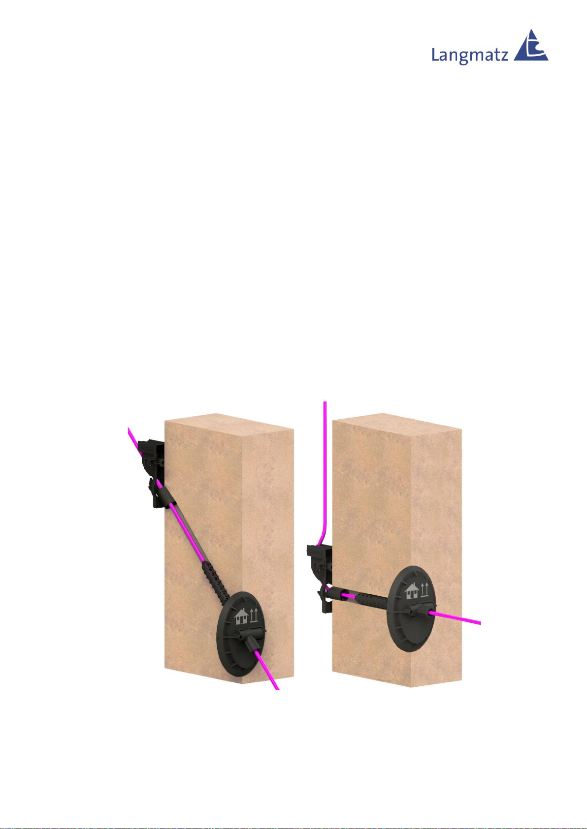
3.1 Installation options.................................................................................................4
3.2 Dimensions ............................................................................................................4
4Package includes.........................................................................................................5
5Required tools..............................................................................................................5
6Installation....................................................................................................................6
6.1 Drill hole.................................................................................................................6
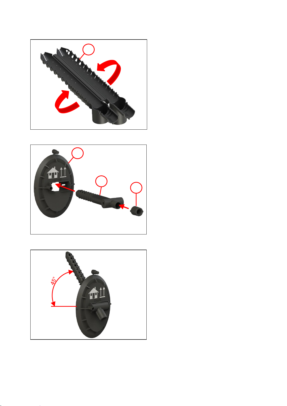
6.2 Preparing the wall duct..........................................................................................7
6.3 Preparing the media cable ....................................................................................9
6.4 Inserting the wall duct..........................................................................................10
6.5 Inserting the media cable ....................................................................................12
6.6 Injecting the sealing foam....................................................................................13
6.7 Continuing the media cable.................................................................................14
6.8 Cover (optional) ...................................................................................................15
7Accessories................................................................................................................15
8Material defects..........................................................................................................16
9Quality management..................................................................................................16
10 Disclaimer/Warranty ..................................................................................................16
11 Disposal......................................................................................................................16
12 Safety information sheet for L100 sealing foam .......................................................16
13 Contact.......................................................................................................................17

3
1 General information
Note!
Any person involved in the installation, operation and repair of the product
must first read, understand and follow these instructions. We accept no liability
for damage and operating malfunctions caused by failure to comply with these
instructions.
In the interest of further development, we reserve the right to change individual assemblies
and accessories as considered necessary for further safety and performance
improvements, while preserving the main features.
The copyright to these instructions remains with Langmatz GmbH.
2 Safety information
The product corresponds to the latest state-of-the-art technology at the time of printing and
is delivered in an operationally safe condition.
Unauthorised modifications, particularly to safety-related parts, are prohibited.
Langmatz GmbH warns against misuse of the product.
The operator is responsible for installing, operating and maintaining the fixtures.
The operating company is responsible for the following:
•Preventing danger to life and limb of users and third parties.
•Ensuring safe operation.
•Precluding downtime and environmental impact due to incorrect handling.
•Ensuring that protective clothing is worn when working with or on the product.
Do not use the product if it is damaged. Please contact the
hotline (see section 13 Contact).
Note!
Applicable occupational safety and environmental protection regulations must
be observed during installation, operation, maintenance or repair.
Warning!
Note the following when using L100 sealing foam:
- Wear protective gloves.
- Keep the sealing foam out of reach of children.
- Sealing foam is irritating to eyes, skin and respiratory organs and may
cause damage to health. In case of contact, rinse eyes thoroughly and
wash skin with soap and water.
- The optimum working temperature is +5°C to +40°C (ideally +10°C to
+25°C).
- Storage temperature: +5°C to +40°C (optimum +20°C).

4
3 Product description
The wall duct is used for the gas- and water-tight sealing of inserted copper or optical fibre
cables in buildings and can be used for wall thicknesses
of from 200 mm.
Properties:
- Gas- and water-tight to 1 bar | Water impact class to DIN 18533
- W1.1-E / W1.2-E / W2.1-E
- Waterproof concrete stress class 1 to DAfStb 2017
- Waterproof concrete stress class 2 to DAfStb 2017
3.1 Installation options
Fig. 1
The system can be installed straight at 90°
(2) or inclined (1) up to 45° upwards.
Installation is identical in both cases.
Straight installation is illustrated in these
instructions.
3.2 Dimensions
Fig. 2
- For wall thicknesses of from 200 mm
- Core hole ø 25 mm (max. ø 26 mm)
2
1
From 200
mm
ø25 (max. ø26)

5
4 Package includes
Fig. 3
Item 1
Item 2
Item 3
Item 4
Item 5
Item 6
Item 7
Item 8
Item 9
Item 10
Guide element
Foam pipe
Outside flange
Dust protection for SpeedNet pipe
Universal seal ø 6 –13 mm
Universal seal 2x ø 7 mm
Dowel nail 6x40 mm
L100 sealing foam cartridge and
mixing pipe
Work gloves
Cover (depending on version)
5 Required tools
Fig. 4
2-part cartridge gun
(e.g. Ponal PP 6) or standard
caulking gun with adapter (1) for 2-
part cartridges.
Not shown:
- Rubber mallet
- Drill ø 25 mm
- Phillips screwdriver
Pozidriv size 2
1
2
3
4
5
1
8
6
7
10
9

6
6 Installation
6.1 Drill hole
Fig. 5
•The substrate must be clean, largely dry,
free of dust and grease, and there should
be no standing water.
•Drill a ø 25 mm (max. ø 26 mm) hole from
the inside to the outside.
•At the drill exit point (if present), cut out
and remove thermal insulation
(polystyrene or rigid foam panels)
including any dimpled sheet that may be
present.
•Caution!
Even out any uneven exterior masonry
around the contact surface of the outside
flange by sanding or with quick-setting
mortar.
Ensure that the entire surface of the
outside flange can be in contact.
•Restore plaster chipping or spalling >50
mm as well as damaged bitumen
coatings in "tanked walls" that are not
covered completely by the outside flange
of the wall duct.
Note: The bitumen coating must be
touched up according to DIN 18533.
Ensure a seamless join to the existing
coating.
Fig. 6
Note for inclined installation:
Trench depth = wall hole exit + 200 mm.
This clearance is needed for installation.
ø 25 (max. ø 26
mm)
min. 200 mm
Trench depth

7
6.2 Preparing the wall duct
Fig. 7
•Fold the foam pipe (1) together.
Fig. 8
•Place the universal seal ø 6-13 mm or
2x ø 7mm (3) on the foam pipe (2).
•Insert the foam pipe into the outside
flange (1).
Fig. 9
Inclined installation is possible up to 45°
upwards.
1
2
3
1

8
Fig. 10
•Remove the dust protection (1) from the
outside flange (2).
1
2

9
6.3 Preparing the media cable
Note: Clean the micropipe before use!
Fig. 11
•Insert the dust protection (1) into the
micropipe ø12 (2).
Fig. 12
•Insert the micropipe ø 7 or ø 10 (1) into
the
dust protection (2).
Fig. 13
•When fitted with micropipes
2x ø 7 mm (2), the dust protection is
already integrated in the universal seal
(1).
Note:
Do not use separate dust protection
here!
1
2
1
2
1
2

10
6.4 Inserting the wall duct
Fig. 14
Note: For installation close above the
base plate, continue with Fig. 16.
•Position the guide element (1) at the
hole and drive in until the base plate is
in contact with the wall.
•Drill a hole ø 6 at least 50 mm deep.
•Drive the dowel nail 6x40 mm (2) into
the wall and tighten.
Fig. 15
•Place the foam pipe with outside flange
(1) in the core hole and insert up to the
beginning of the snap lug
(note Fig. 18).
•Drive in the foam pipe with outside
flange with a rubber mallet until the
outside flange is fully in place.
Note:
Alternatively, the
guide element (1) can also be installed
after the outside flange (2), but note:
the wall duct must be completely
installed before foaming!
Continue with Fig. 18
Fig. 16
When installing close above the base
plate, cut off the lower part of the guide
element.
•Cut off the guide element (1) below the
marking ridges.
1
2
1
1
Building / Inside
Ground side / Outside
Building / Inside

11
Fig. 17
•Position the shortened guide element
(1) at the hole and drive in until the
base plate is in contact with the wall.
•Drill a hole ø 6 at least 50 mm deep.
•Drive the dowel nail 6x40 mm (3) into
the wall and tighten.
•Place the foam pipe with outside flange
(2) in the core hole and insert up to the
beginning of the snap lug.
•Drive in the foam pipe with outside
flange with a rubber mallet until the
outside flange is fully in place.
Note:
Alternatively, the
guide element (1) can also be installed
after the outside flange (2), but note:
the wall duct must be completely
installed before foaming!
Fig. 18
Note:
When inserting the outside flange (2), pay
attention to the direction of installation:
install with the "house pointing up" (1).
1
2
1
2
3
Building / Inside
Ground side / Outside

12
6.5 Inserting the media cable
Fig. 19
Note:
Keep the media cable (2) free of grease in
the foaming area (1).
Fig. 20
•Pull the media cable (2) straight and
insert it through the foam
pipe (1) from the ground side.
Note:
Ensure sufficient cable length (on the
basement side)! The cable can no
longer be pulled further once the L100
sealing foam has been injected.
2
1
2
1
Building / Inside
Ground side / Outside
Building / Inside
Ground side / Outside

13
6.6 Injecting the sealing foam
Fig. 21
Note:
- Reconfiguration is no longer possible
after filling with foam!
- Use a suitable cartridge gun or
alternatively
an adapter (see chapter 6.8) for the
cartridge (2).
Observe the expiry date! Refer to the
cartridge label.
•Put on work gloves.
•Place the cartridge (2) in the cartridge
gun (3).
•Screw on the mixing nozzle (1).
•Fill the mixing nozzle using the cartridge
gun.
•Squirt the next two strokes into the
packaging bag.
Fig. 22
•Insert the mixing nozzle (1) into the
backfill opening (2).
•Inject the L100 sealing foam and always
empty the cartridge completely.
•Leave the mixing nozzle with cartridge
in the backfill opening for a few minutes
(for disposal, see section 11).
1
2
1
2
3

14
6.7 Continuing the media cable
Fig. 23
Note:
- Before continuing, remove the dust
protection and, if necessary, use a
suitable tool to clip off the micropipe.
- Only continue the media cable
upwards after the fibres have been
blown in!
•Guide the media cable (1) over the
guide element (3) to the wall.
•Remove the wedge (2) from the guide
element.
Fig. 24
•Secure the media cable (1) with the
wedge (2).
•Insert the wedge flush
into the guide element (3) from above.
Caution:
Pay attention to the direction of
installation of the wedge, see Fig. 25.
Fig. 25
Item 1
Item 2
For media cable ø 7 mm
For media cable ø 10-13 mm
1
2
1
3
2
3
1
2

15
6.8 Cover (optional)
Fig. 26
•Place the cover (1) on the guide
element (2).
7 Accessories
Article number
Designation
Figure
700732500/012
Accessories kit with adapter
for cartridge gun
Packaging unit: 12 pc.
094592020/012
Cover for wall duct
Packaging unit: 12 pc.
1
2

16
8 Material defects
Langmatz GmbH assumes liability for material defects in the product
as per Section 434 BGB (German Civil Code) for 24 months, starting from the date on the
purchase receipt.
Within the scope of liability, all parts that become damaged due to manufacturing or material
errors will be replaced or repaired free of charge.
The purchaser must report any deficiency complaints immediately in writing.
Claims for damages by the purchaser due to material defects or for whatever legal reason
will not be accepted.
Any damage or failure caused by the following are also excluded from liability
- Incorrect use,
- Natural wear and tear
- Intervention by third parties.
We accept no liability for damage caused by force majeure or transport.
Repairs due to a deficiency complaint do not extend the warranty periodfor the replaced parts
or the product.
This product conforms to the latest state-of-the-art technology. Nevertheless, if you experience
any problems with it, please contact our hotline (see section 13 Contact).
9 Quality management
The Langmatz GmbH quality management system is certified to DIN EN ISO 9001.
10 Disclaimer/Warranty
The information in this technical document is presented appropriately and correctly in
accordance with the technical regulations and to the best of our knowledge. However, this
does not confer any guarantee of particular characteristics. In this context, the operator of the
products supplied by Langmatz GmbH is expressly obliged to decide, based on their own
judgement, whether the products are suitable and appropriate for the application or use being
considered. The product liability accepted by Langmatz GmbH relates exclusively to our
conditions of sale, delivery and payment. Langmatz GmbH accepts no liability due torandom,
indirect and resultant consequential damage, as well as any damage attributable to any use
of the product other than for its intended purpose described.
11 Disposal
Dispose of the contents and containers in accordance with all local, regional, national and
international laws.
12 Safety information sheet for L100 sealing foam
At www.q-wa.net/SDB/0000

18
70 071 4452 / 001 │ As of 22.06.2022 │ Translation of the Original Installation Instructions
Table of contents
Other Langmatz Industrial Equipment manuals