samlexsolar MC4-2 User manual

Owner's
Manual
Please read this
manual before
installing your
connectors
Solar Panel
Multi-Contact
Connectors
MC4-2
1
INTRODUCTION
MC4 Multi-Contact Connectors (Fig. 1)
Samlex's MC4-2 Kit contains 1 male and 1 female MC4 solar panel connector. This type of connector system
is easy to install and uses “snap-in” safety locking tabs to lock two mating connectors, thereby avoiding
unintentional disconnection. Also when locked, the mating contacts are sealed against ingress of dust and
water. Specications are as follows:
• Connectors supplied with this kit are for use with wire size AWG # 10 or AWG # 12 with outer insulation
diameter of 3 – 6 mm
• Contact diameter Ø 4 mm
• Maximum rated current - 30 A
• Maximum system voltage - 1000 V
• Degree of ingress protection when connected and properly locked - IP67
• Temperature range 40°C to +90°C
• TÜV Rheinland – type approved, UL listed
Construction of MC4 Connectors (See Fig. 1)
The connectors can be crimped / soldered to wire size AWG #10 or AWG # 12 with an outer insulation
diameter of 3 to 6 mm.
1. Outer insulated housing
2A. Tin plated, Copper female mating contact
2B. Tin plated, Copper, male mating contact
3. Nut with internal rubber bush for tightening the sealing around the wire entry
4. Crimping area
1
2A 6
3
2B
4
MC4 Female Connector (PV-KBT4/6I) MC4 Male Connector (PV-KST4/6I)
Note: “Male” and “Female” designation is based on the mating characteristic
of the internal mating contact (see 2A and 2B)
13
4
Fig. 1. MC4 Male and Female Connectors
The Male and Female MC4 Connectors consist of the following components (See Fig. 1).
• Outer insulated housing with locking arrangement (1 of Fig. 1)
• Tin-plated Copper metallic male & female mating contacts (2A and 2B of Fig. 1). The wire is placed in
the crimping area (4 of Fig 1) and crimped with a special crimping tool
• Nut & internal rubber bush (3 of Fig. 1). When the nut is tightened, the internal rubber bush is
compressed around the outer jacket of the cable and thus, provides water-tight sealing.

2
MC4 Connector – Locking Arrangement (Fig. 2)
Two locking tabs (1 of Fig. 2) are provided on the MC4 Female Connector. Two corresponding locking slots (2
of Fig. 2) are provided on the MC4 Male Connector. When the two connectors are coupled, the locking tabs
slide into the locking slots and secure.
To uncouple the two connectors, press the ends of the locking tabs as shown (3 of Fig. 3) to release the
locking mechanism.
1. Locking tabs on the MC4 Female Connector
2. Locking slots on the MC4 Male Connector
3. Press here to release the locking tabs. Make sure that no current is owing
when uncoupling is attempted.
1
3
312
2
Fig. 2. Snap-in Locking System
Wire Connections on Solar Panels (See Fig. 3)
Most solar panels come with approximately 3 ft of Positive (‘+’) and Negative (‘-‘) wire. One end of each wire
is connected to the junction box of the panel. In most solar panels (for example, solar panels manufactured
by Samlex Solar), the other end of each wire is terminated with an MC4 connector. The Positive (‘+’) wire has
a Female MC4 Connector and the Negative (‘-‘) wire has a Male MC4 Connector. To extend the length of the
wires of these solar panels for connection to a charge controller, combiner box or grid-connected inverter, an
extension wire is required with corresponding Male and Female MC4 Connectors.
Solar Panel
MC4 Male Connector (Marked “-”)
MC4 Female Connector (Marked “+”)
Fig 3. Solar panel with MC4 Connectors

3
Warning!
When the surface of the solar panel / array is exposed to sunlight, a DC voltage appears at the
output terminals turning it into a live voltage source. For example, a 24 V nominal solar panel my
put out an open circuit voltage of around 45 VDC that may produce electrical shock. Multiple so-
lar panels connected in series (to increase the output voltage) will put out higher lethal voltages
To avoid any electrical shock hazard during installation, make sure that the solar panel / array is
covered with an opaque (dark) material to block solar irradiation.
INSTALLATION
Installation procedure (See Fig. 1 and Fig. 2)
The MC4 connectors provided are compatible for use with AWG #10 or AWG #12 wire with outer insulation
diameter 3 – 6 mm. Wires may be single conductor, Type UF (Underground Feeder - marked as sunlight
resistant), Type SE (Service Entrance) or Type USE/USE-2 (Underground Service Entrance).
1. Strip 1/4” of the wire insulation using a wire stripper. Take care not to cut individual strands.
2. Insert the bare conductor into the crimping area (4 of Fig. 1) of the metallic mating contact and crimp
using a special purpose crimping tool. The end may be soldered if the crimping tool is not available.
Take care that the solder does not ow beyond the crimp area.
3. Insert the metallic mating contact with the crimped wire through the cable gland into the insulated
housing, till the metallic pin ts snug into the housing.
4. Tighten nut (3 of Fig.1) so that the rubber bush is compressed around the wire entry to ensure proper
sealing.

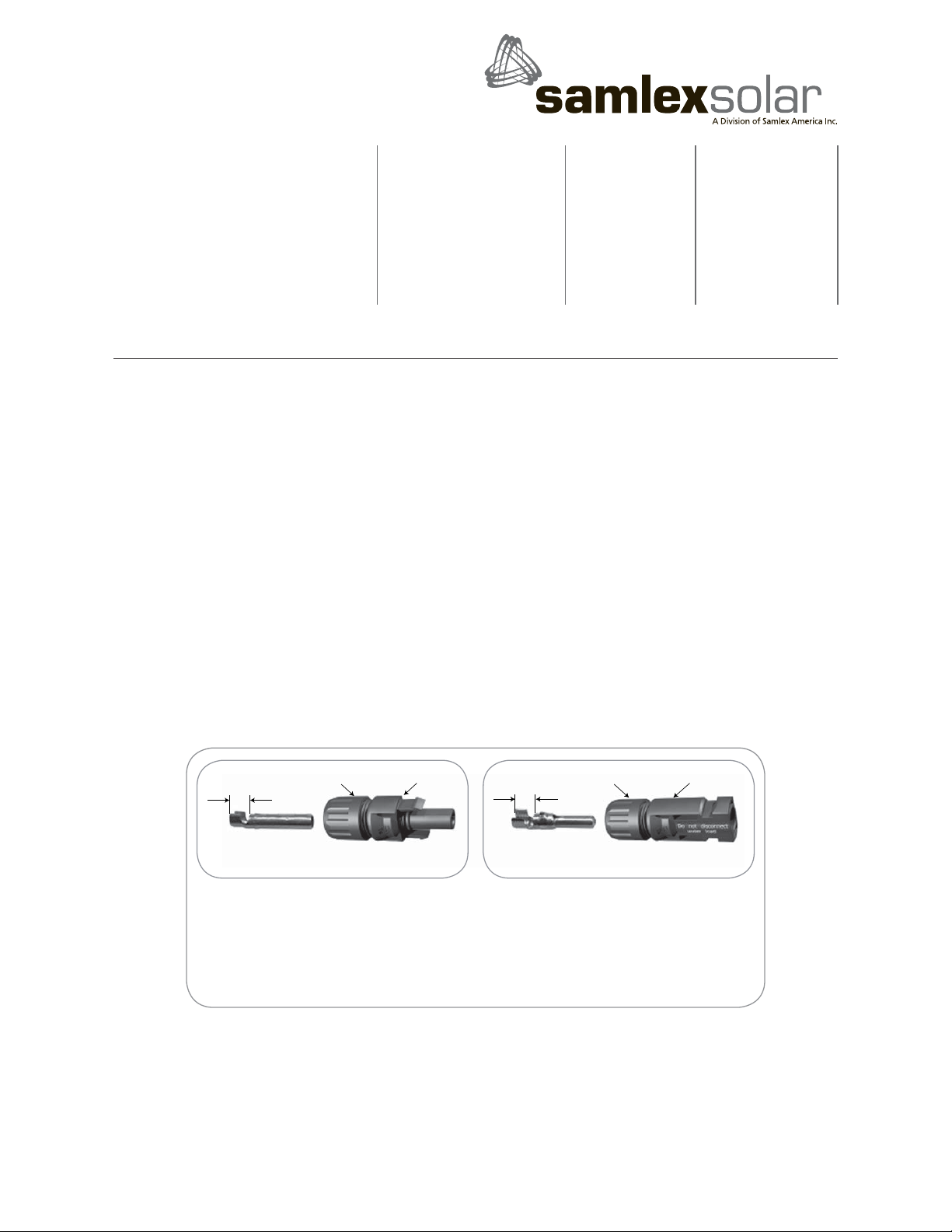
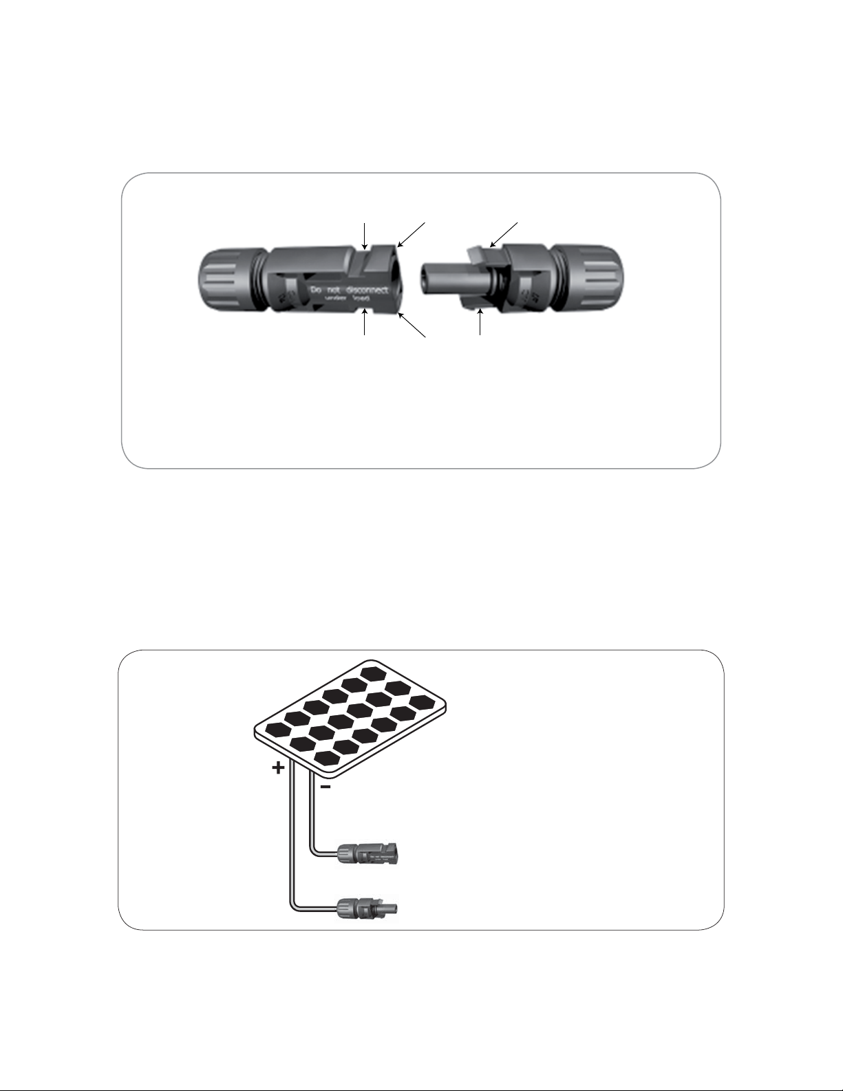
230-2010_MC4-2_ Solar_Panel_Multi-Contact_Connectors_Manual_Jan2010
4
110-17 Fawcett Rd
Coquitlam, B.C.
Canada V3K 6V2
T: 604 525 3836
F: 604 525 5221
TF: 1 800 561 5885
e-mail: samlex@samlexsolar.com
website: www.samlexsolar.com
2 YEAR LIMITED WARRANTY
The MC4-2 Solar Panel Multi-Contact Connectors supplied by Samlex America, Inc. (the “Warrantor “) are
warranted to be free from defects in workmanship and materials under normal use and service. This warranty
is in effect for 2 years from the date of purchase by the user (the “Purchaser “).
For a warranty claim, the Purchaser should contact the place of purchase to obtain a Return Authorization
Number. The defective part or unit should be returned at the Purchaser’s expense to the authorized location.
A written statement describing the nature of the defect, the date of purchase, the place of purchase, and the
Purchaser’s name, address and telephone number should also be included.
If upon the Warrantor’s examination, the defect proves to be the result of defective material or workmanship,
the equipment will be repaired or replaced at the Warrantor’s option without charge, and returned to the
Purchaser at the Warrantor’s expense.
No refund of the purchase price will be granted to the Purchaser, unless the Warrantor is unable to remedy
the defect after having a reasonable number of opportunities to do so. Warranty service shall be performed
only by the Warrantor. Any attempt to remedy the defect by anyone other than the Warrantor shall render
this warranty void. There shall be no warranty for defects or damages caused by faulty installation or hook-
up, abuse or misuse of the equipment including exposure to excessive heat, salt or fresh water spray, or
water immersion.
No other express warranty is hereby given and there are no warranties which extend beyond those described
herein. This warranty is expressly in lieu of any other expressed or implied warranties, including any implied
warranty of merchantability, tness for the ordinary purposes for which such goods are used, or tness
for a particular purpose, or any other obligations on the part of the Warrantor or its employees and
representatives.
DISCLAIMER OF LIABILITY
There shall be no responsibility or liability whatsoever on the part of the Warrantor or its employees and
representatives for injury to any persons, or damage to person or persons, or damage to property, or loss
of income or prot, or any other consequential or resulting damage which may be claimed to have been
incurred through the use or sale of the equipment, including any possible failure of malfunction of the
equipment, or part thereof.
The Warrantor assumes no liability for incidental or consequential damages of any kind.
Samlex America Inc. (the “Warrantor”)
110-17 Fawcett Road
Coquitlam BC V3K 6V2 Canada
(604) 525-3836
Table of contents
Other samlexsolar Cables And Connectors manuals