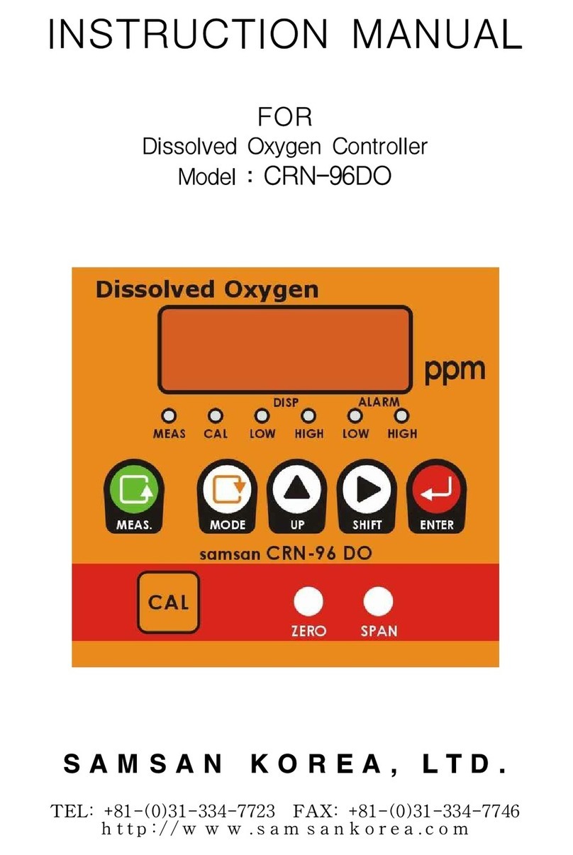
Samsan Korea CRN-96RC User manual

INSTRUCTION MANUAL
FOR
Residual Chlorine Controller
Model : CRN-96RC
S A M S A N K O R E A , L T D .
TEL: +81-(0)31-334-7723 FAX: +81-(0)31-334-7746
h t t p : / / w w w . s a m s a n k o e a . c o m

- 1 -
DIGITAL TY E RC Controller
Thank you very much for your purchasing of
Advanced SAMSAN CROWN CONTROLLER with microprocessor.
This controller has been checked and tested thoroughly to meet prescribed
specifications and certain safety standards by our inspector before ex-factory,
however, surely check the state of controller outside and accessaries when delivered.
Also Read all instruction manuals and understand basic functions & full operating
methods for complete use.
1. FEATURES
Advanced SAMSAN CROWN CONTROLLER with microprocessor
Condensed in a compact DIN size (96×96m/m), versatile functions provide more
simplicity in operation and more efficiency in performance, in addition to accurate
monitoring results.
With the appropriate sensors and accessaries, SAMSAN CROWN CONTROLLER can
serve as the most suitable and effective cost monitoring system to meet process,
waste water and control applications.

- 2 -
1-1
With microprocessored controller's various functions and design of one touch
button, you can
get more effective, reliable data and very simple setting.
1-2 Designed for using out-put of signal and alarm
(DC 4~20㎃ or 1~5V and others)
1-3 With 3 Digit Digital Display, Reading & setting are very simple by appearance of
each message.
1-4 Isolator is equipped for transmission of stable data with isolated DC 4~20㎃ or
1~5V output and you can connect with personal computer and data logger
directly.
1-5 Designed to set high and low alarm for controlling of water quality in process,
waste water and your applications.
1-6 Equipped with Automatic Temperature Compensation for more accurate
monitoring results and appearance.
1-7 DIN (96×96m/m) size for simple installation and maintenance.
1-8 Equipped with power switch for protection of controller by ON/OFF of power
supply while setting or A/S.
1-9 Equipped with EE ROM, SAMSAN CROWN CONTROLLER can hold all set
values of preset parameters while power is OFF and when power become ON,
they can continue to measure and monitor with all values set before.
2. S ECIFICATIONS
2-1 RC CONTROLLER
Model
CRN-96RC
Range
0.0 ~ 2..0 ppm
( O TION: 0 ~ 5 / 10.0 ppm )
SA(Sensitivity Adjustment)
0.1 ~ 0.6 ppm ( ± 0.3 ppm )
Shift
± 0.5 ppm
Accuracy
± 3% Full Scale
Ambient Temperature
-5
℃
~ 45
℃
Output
DC 4~20mA ( R.L. O~500
Ω
)
DC 1~5V
( Option: Isolation )
Alarm
High, Low Relay ( 1a1b )
anel Cut
92 (W) × 92 (H) mm
ower Source
AC 100/220V ±10%, 50/60㎐

- 3 -
2-2 Cable : This cable is special for RC controller and used to connect between
the controller and connector box.
(1) Model : SC-10
(2) Size : 6
ψ
(3) Length : 5m ( standard ), Max. extension : 20m ( option )
2-3 Connector box
(1) Model : SCB-10
(2) In case of over than 3m between controller and electrode holder, install
with connector box near electrode holder and connect with SAMSAN
special cable surely in connection between connector box and controller.
2-4 RC Electrode
(1) Model : SCR-600
(2) Liquid Temp. : 0 ~ 40
℃
(3) Type : Galvanic electrode that test powder isn't needed
2-5 Holder
(1) Model : SH-20 ( wall mounted type )
(2) Mat'l : Acril
(3) Sampling Water
- Water quantity : 0.5 ~ 1.0
ℓ
/min
- Inlot pressure : Less than 3 kgf/cm
- Outlot pressure : Opening to atmosphere
- pH : 6 ~ 8 pH ( constant )
- Liquid Temp. : 0 ~ 40
℃
( constant )

- 4 -
3. NAME OF ARTS
3-1 Display : d
isplay of measured value, set-value, parameter's set contents
3-2 State lamps
(1) MEAS : when measuring, LED lamp on
(2) CAL : when calibration, CAL switch-on and lamp on,
HIGH/LOW Relay off
(3) DIS LAY
LOW : when set-value(related with LOW) is appeared, lamp on
LOW set / SA / SHIFT
HIGH : when set-value(related with HIGH) is appeared, lamp on
HIGH set / SA / SHIFT
(4) ALARM
LOW : when LOW ALARM, lamp on
HIGH : when HIGH ALARM, lamp on
3-3 Function buttons
(1) MEAS : set MODE
→
measuring MODE
CAL on
→
CAL off
(2) MODE : using when reading and changing of set-value
(3) U : using when changing of set-value in set-MODE
(4) SHIFT : using when changing of figure's place
(5) ENTER: using when finishing of setting
1. DISPLAY
2. STATE LAMPS
3. FUNCTIONS
4. CAL VOLUME

- 5 -
3-4 CAL volume
: used when calibration with buffer solution
(1) ZERO(VR) : using when calibration of ZERO
(2) S AN(VR) : using when calibration of S AN
4. O ERATION
4-1 Setting flow chart
4-2 Changing method
(1) used when increasing of twinkling figure
U
(2) used when moving of twinkling figure to right side
SHIFT
(3) used when saving of setting value
ENTER
After changing of set-value, if ENTER button is not pushed,
it will be returned to former set-value.
MEAS
(enter to state of measurement)
push MODE button
LOW set (LOW display lamp-on)
HIGH set (HIGH display lamp-on)
LOW SA (LOW display lamp-on)
LOW SHIFT (LOW display lamp-on)
HIGH SA (HIGH display lamp-on)
HIGH SHIFT (HIGH display lamp-on)
MODE
MODE
MODE
MODE
MODE
MODE
push MODE button over than 5 seconds
․output relay off in setting routine
․If any button is not operated for
30 seconds in setting routine,
it will be automatically changed to
measuring mode

- 6 -
5. S.A.(Sensitivity Adjustment) & SHIFT
5-1 S.A.(sensitivity adjustment)
: When ON and OFF with 1 point, out-put is chattered and easy to
receive influences of any noises, however, if you set the width of
S.A. as following diagram, stable control is possible.
Setting is possible from 0.1ppm to 0.6ppm (±0.6ppm) and it was set as
0.1ppm(±0.05ppm) when ex-factory.
Set example) LOW set : occasion of lower limit 5.0ppm
S.A : 0.2ppm
SHIFT : 0.0ppm
Set example) HIGH set : occasion of upper limit 1.0ppm
S.A : 0.4ppm
S.A 0.2 ppm
▲
0.4ppm
0.6ppm
ON
OFF
O
U
T
P
U
T
5.0ppm
setting value
1.0ppm
setting value
▲
1.2ppm
ON
OFF
O
U
T
P
U
T
▲
0.8ppm
ON
S.A 0.4 ppm

- 7 -
SHIFT : 0.0ppm
5-2 SHIFT
: A constant error is occured against target value when ON and OFF.
This error is called as off-set and this off-set can be controlled to
target value without any errors, if you use this SHIFT function in
SAMSAN CROWN controllers.
Setting is possible from 0.0ppm to 0.5ppm and it was set as 0.0ppm
when ex-factory.
Set example) LOW set : 5.0ppm
S.A : 0.2ppm
SHIFT : -0.1ppm
Set example) HIGH set : 1.0ppm
S.A : 0.4ppm
SHIFT : +0.2ppm
S.A 0.2 ppm
▲
0.3ppm
ON
OFF
5.0ppm
setti g value
O
U
T
P
U
T
▲
1.4ppm
ON
OFF
S.A 0.4 ppm
1.0ppm
setti g value
O
U
T
P
U
T

- 8 -
6. INSTALLATION & WIRING
6-1 Installation environment
: Install at good conditioned place as follows
(1) Airy place ( ambient temperature : -5
℃
~40
℃
)
(2) Adequate protection should be provided to keep the controller from
being exposed to direct sunlight or rain
(3) Moistureless place that ambient humidity is less than 85%
(4) A place without the mechanical vibration
(5) A place with sufficient space for easy maintenance and wiring
(6) A place without dust, corrosive gas and any influences of electronic
power
6-2 Installation method
(1) anel mounting type
※
Refer to out-drawing for panel cutting
(2) Insert 2 eas of mount bracket in the upper and lower holes and
fasten the bolts with +
○
driver
6-3 Connection of sensor cable
:
Cable connector should be kept in dry and clean to get a stable value
(1) Standard cable length is 5m
In case of extension over than 5m, use the connector box and
SAMSAN CROWN cable for RC.
(2)
Install at the place without any influences due to motors of machinery
(3) Contact to our technical sales dept. in case of using Temperature
Compensation electrode.
A : ANODE
K : CATHODE
T. T : no connection
E : SHIELD CABLE
※
Refer to following drawing for wiring to terminal.
6-4 Connection of output cable
(1) Output signal of DC 4~ 20mA against measuring range come out.
※
Max. load resistance : 500
Ω
0.00 ppm
→
4 mA
0.50 ppm
→
8 mA
1.00 ppm
→
12 mA
1.50 ppm
→
16 mA
2.00 ppm
→
20 mA

- 9 -
(2) Output
6-5 Connection of power cable
: Connect with correct voltage
(1)
ower switch is attached to terminal board in the back of the controller
(2) Surely ground for your safety
7. CALIBRATION & O ERATION
7-1 ZERO Calibration
( Residual chlorine concentration of sample water is in case of less
than 0.5ppm)
(1) Close the stop valve in sampling line and make for the water not
to be entered to holder.
15~20minutes later, residual chlorine concentration will be to "0"
if it's electrolyzed.
(2) Then adjust to "0"ppm with ZERO volume on RC controller
( Residual chlorine concentration of sample water is in case of over
than 0.5ppm)
(1) You need much time till it's changed to "0", in this case, immerse
residual chlorine electrode in beaker with municipal water of
residual chlorine concentration 0 ppm. If it's stabilized, adjust
to "0"ppm with ZERO volume on RC controller.
7-2 S AN Calibration
(1) Measure residual chlorine value of sample water with color
comparison Meter. Then adjust the value that's appeared
in color comparison meter with S AN volume of RC controller.
If sample water concentration is low, use liquid for S AN of
0.5~ 1.0 ppm. If it's stabilized, adjust with S AN volume on
RC controller.
Rec rder r P r
PID C ntr ller
C ntr ller
+
○
+
○
+
○
-
○
C ntr ller
+
○
-
○
-
○
-
○
Rec rder r P r
PID C ntr ller
Rec rder r P r
PID C ntr ller
※
Whole load resistance of all
output receiver is max. 500
Ω
.

- 10 -
7-3 CAL Volume Adjustment
(1) ut CAL. MEAS. Switch to CAL position before entering to
continuous measuring.
(2) Adjust to 1.0 ppm with CAL volume.
Notice : After you use the RC controller, if 1.0ppm don't appear on
RC controller, you should wash or re-generate or change
the electrode because electrode's sensitivity become bad.
7-4 Measure continuously, adjusting drain valve if calibration is finished and
calibrate ZERO, S AN in 1~ 2 weeks.
8. REGENERATION & STORAGE OF ELECTRODE
8-1 Regeneration
: In case that calibration is impossible due to becoming bad of
electrode sensitivity, Regenerate electrode as follows.
(1) Wash Anode & Cathode cleanly in 3% HCL with soft brush.
(2) Then clean them with clean water.
(3) Make 100ppm NaOCL and put the electrode in 100ppm NaOCL
for over than 1 day after connecting Anode cable with Cathode
cable in the end of lead cable of electrode.
(4) Calibrate after driving with regenerated electrode for over than
3 hours.
8-2 Storage
: In case of stop of driving for a long time, separate electrode from
holder and storage in clean water in connecting Anode cable with
cathode cable in the end of lead cable. Don't open to atmosphere.
9. CHANGE OF CARTRIDGE FILTER SAM LING LINE
Change cartridge filter in proper time because it's difficult to get
stable value, if filter is polluted.
10. TROUBLE SHOOTING
In case of having any troubles in RC controller, surely check the
followings.
10-1 Basic checking points
(1) Do you use this RC controller on the purpose of measuring
residual chlorine that generates when chlorine gas or NaOCL
is poured into ?

- 11 -
10-2 Don't total residual chlorine occupy the majority due to having
much NH3compound in the water ?
trouble
cause
remedy
Not to indicate
Electric power is supplied
to controller ?
Turn on the power switch.
Calibration is correct ?
Re-calibrate by instructions.
Don't you have any
problems to connect with
cables ?
Refer to terminal board of
item 12.
Don't you have any
problems to holder and
over-flow level ?
Adjust stop valve.
Residual chlorine is
included in
sampling water ?
Check with color comparison
meter.
Isn't the filter plluted ?
Change the filter to new one.
pH value of sampling
water isn't
over than pH 8 ?
Adjust pH value between
pH 6 and pH 8.
Not to calibrate and
instructing valvue
go down
Sensitivity went down due
to pollution of electrode.
Clean the electrode and
regenerate.
In case of opening the
electrode to atmosphere
for a long time.
Drive continuously till
instructing value is appeared.

- 12 -
11. DIMENSIONS
MIN.
150
MIN. 130
92.0
±
0.5
92.0
±
0.5
91
145
10
PANEL-CUT SIZE (UNIT: mm)
96mm
96mm

- 13 -
12. TERMINAL BOARD
13. INNER STRUCTURE
LOW
HIGH
RELAY
POWER
TRANS
OUTPUT 4-20mA
RC RANGE CARD
ZERO
SPAN
BIAS
GLASS (M)
FUSE 250V/0.5A
1
2
3
4
5
6
7
8
9
LOW
a.(NO)
b.(NC)
COM
HIGH
a.(NO)
b.(NC)
COM
POWER
200/220V
100/110V
ON
OV OFF
220
110
0
LOW ALARM
CONTROL
AC250V 4A
(R-LOAD)
HIGH ALRAM
CONTROL
AC250V 4A
(R-LOAD)
POWER
SOURCE
GROUND
12
13
14
15
16
17
SENSOR
A
K
EARTH
T
T
OUTPUT
+
4-20mA
-
GND
K
T
T
+
-
F
18
G
RC SENSOR
ATC(OPTION)
Max.500
Ω
Output
10
11
A
Table of contents
Other Samsan Korea Controllers manuals