4
Description
Power Supply
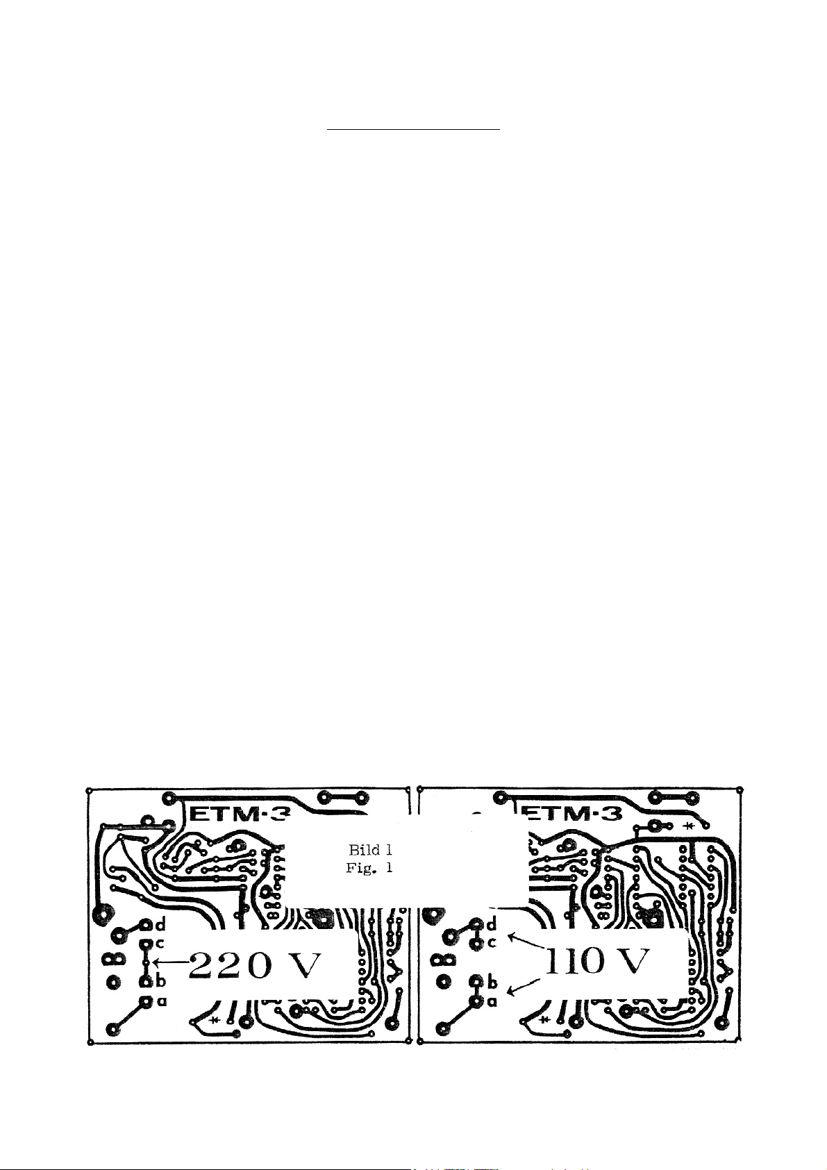
The power transformator may be operated at either 220···240 or 110···120 volts AC suitable chan-
ging of connections a-b-c-d. (Fig. 1)
For 220···240 volts operation connect solder lugs b-c, for 110···120 volts operation connect solder
lugs a-b and c-d.
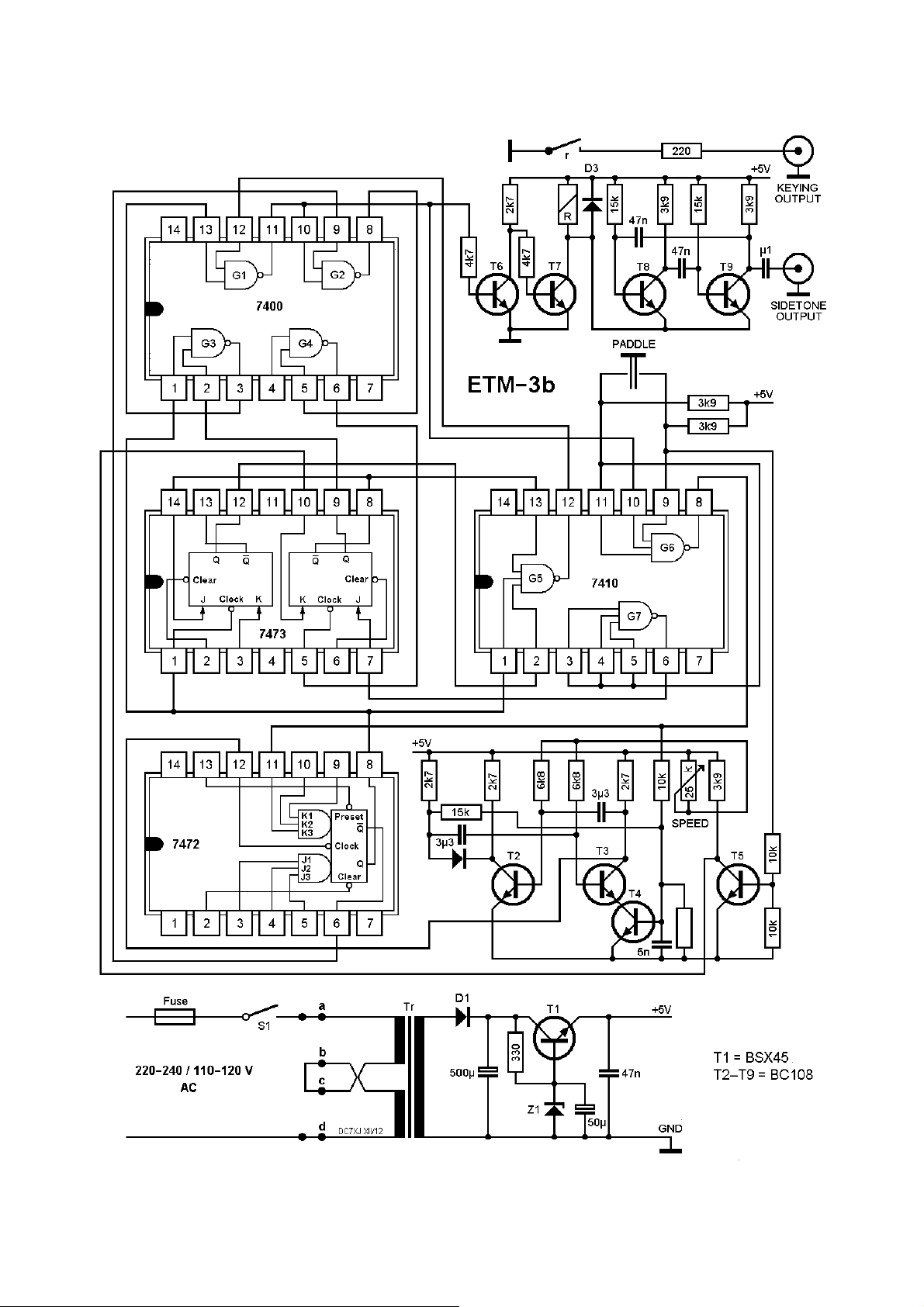
The power supply serves as a stabilized a.c. operated supply.
Keyer operation
The time base is an instant starting oscillator made up of the transistors T2, T3 and T4. It takes 2
pulses from the time base for every dot at the output of Flip-Flop F2. Under quiescent conditions
gate G6 holds Flip-Flop F2 in the set condition.
By actuation of either one or both of the key-levers, G6 allows the timing pulse to toggle F2. If the
key is opened before completion of a character will be completed anyway.
If key lever is moved to the dot side, dot pulses of F2 will feed G3, G1 and T6 and drives T7. T7 ac-
tuates the reed-relay and the sidetonegenerator consisting of transistors T8 and T9.
Moving key lever to the dash side, dash Flip-Flop F3 will be toggled.
G5 adds pulses of F2 and F3 and feeds T6 through G1, which drives transitor T7.
Squeezing both key levers, F4 toggles F3 and at T7 occurs alternating dot and dash pulses.
Mode of keying
The ETM-3 keyer may be operated as an ordinary el-bug or using the SQUEEZE-method.
1. By mutual activation of each of the seperate levers it is possible to operate the keyer in the con-
ventional manner.
2. SQEEZE keying requires simutaneous squeezing of the double paddle. A great advantage of
the SQUEEZING method is the possibility of keying characters like C, Q, Y F, L, ar, sk with fewer
motions of the paddle compared to the conventional manner of keying.
Example: a C is keyed by squeezing of both paddles starting with the dash lever.
Adjustment of paddle
Remove both mounting screws on the rear panel and remove the chassis from the case.
CAUTION: BE SURE TO DISCONNECT THE LINE-CORD BEFORE REMOVING THE CHASSIS !
The paddle uses silver contacts. The gap of either dot and dash side adjustable by means of two
milled screws.
The tension is adjustable by means of a single setscrew using an alien wrench for both dots and
dashes. (Fig. 2)
Keying output
The main davantage is a dry reed switch. The switching element is a reed capsule. It consists of
two overlapping Rhodium coated ferromagnetic reeds, separated by small air gap sealed in a glas
capsule. Reedcapsules are ideally suited to high speed switching application. When a magnetic
field is induced in the reed they are attracted to each other and make contact.
An inert gas atmosphere in the sealed capsule prevents contact contamination and corrosion. The
rapid increase of flux density results in the snap action of the contacts.
Modern transimitters use grid-block-keying. To prevent Rf-radiation from the keying input, a capaci-
tor of approx. .005 µF is connected across the jack. When the transmitter is not keyed the capacitor
shows full blocking voltage. When this capacitor is discharged during keying periods across the
reed contacts high current appears.
A resistor of 220
Ω
in series with the output jack will limit the current surge to admissible values.