Ошибка! Используйте вкладку "Главная" для применения 제목 8,표준 제목 1 к тексту, который должен здесь
отображаться.
IV © SAMSUNG Electronics Co., Ltd.
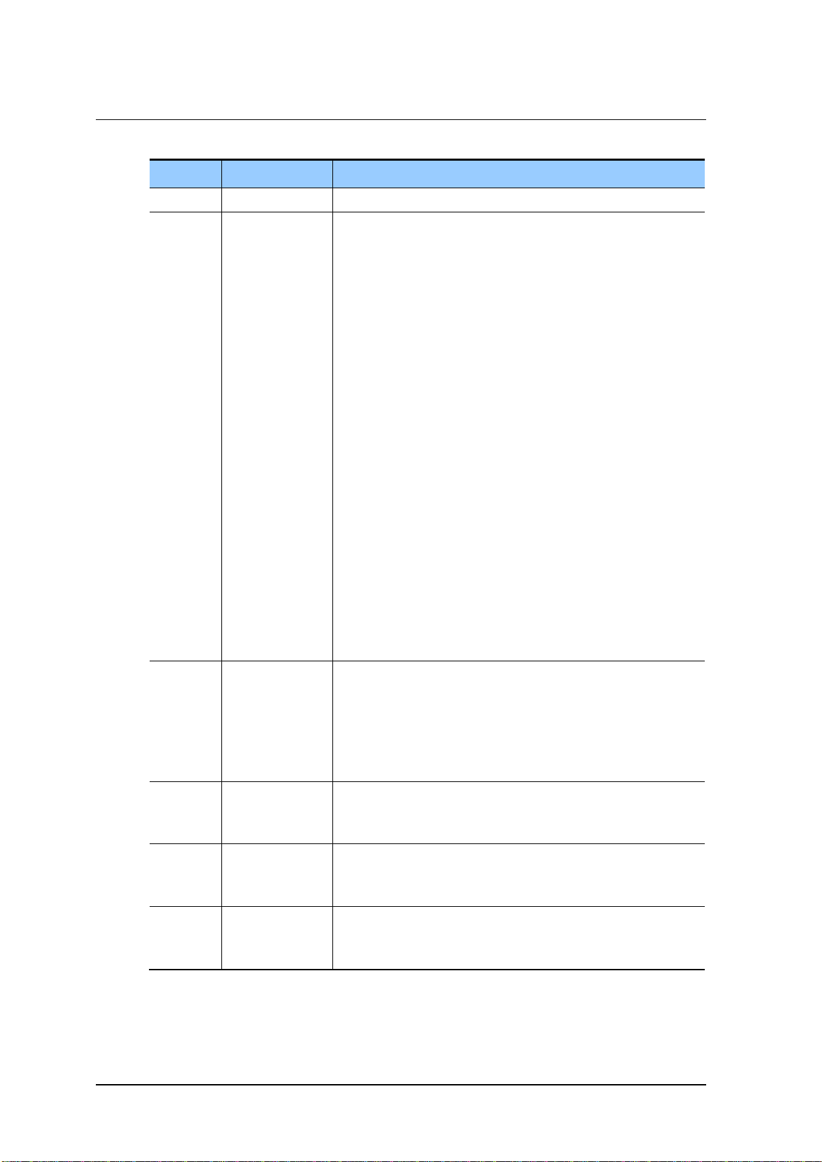
Revision History
- Modifying the brand name
(Before: OfficeServ SME Installation Guide,
After: OfficeServ 7200 Installation Manual)
- Modifying edit format (Deleting ED at page header)
- Modifying cover page design and overall edit format and
improving sentence expression
- Introduction: Modifying the related documents
Chapter 1: Change of power supply standard, change of
package product, addition of external rectifier.
Chapter 2: Changed method of Installing cabinets on the wall,
additional update of grounding connection
Chapter 3: Change of jumper setting for interface board,
change of cabinet configuration and specification, WIM board
correction, additional update for LIM-P board, update for
connecting Power Fail Transfer
Chapter 4: Additional update for connecting external rectifier
Chapter 6: Additional update for C.O line connection
Chapter 7: Changed function for RJ-45 pin for TEPRI, 16SLI,
8HYB, and 16DLI board, change of connection diagram of IP
phone, change of wireless LAN equipment connection,
additional update of terminal connection
Chapter 8: Additional checking update for fan operation
Addition of Abbreviation
- Changed the name of the LIM-P board to ‘PLIM’.
- Boards added: PLIM2, 8TRK2, 16TRK, TEPRIa, 4HTRK,
MGI16, 8SLI2, 8COMBO2, GPLIM, GPLIMT, GSIM, GSIMT
- 4DSL, WBS24, 4WLI, WIP-5000M are deleted.
- Added SMT-R2000 and SMT-W5100
- Added MP20
- Added MP20S, UNI, 2BRM, 4TRM , 4DLM, 4SL2, 4SLM,
4SWM, and OAS
- Deleted MCP, TEPRI and MGI due to product discontinuity
- Deleted 8SLI, 16DLI, 16SLI, 8HYB, 8HYB2, 8COMBO, GPLIM,
GSIM, 4SWM, MFM, RCM due to product discontinuity
- Added CNF24, IRM
- Manual edition allocation method is changed.
(Ed.05 Ver.6.0)
- 8SLI3, 16SLI3, 8COMBO3, SVMi-20i are added.