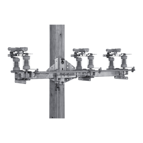
S&C Mark V Instruction manual

S&C
Circuit-Switchers
-
Mark
V
Integer Style
Outdoor
Transmission
34.5
kv
through
69
kv
I
INSTRUCTIONS
For FieldAssembly and Installation
[TABLE
OF
CONTENTS
I
Section Page Number Section Page Number
INTRODUCTION
........................................
1
INSTALLATION
.........................................
7
BEFORE STARTING INSTALLATION
......................
.5
FINA1,CHECKS
........................................
10
1
INTRODUCTION
I
1
0
The equipment covered by this publication mustbe
selectedfor aspecificapplicationand it mustbe
installed,operated,andmaintainedbyqualified
personswhoarethoroughlytrainedandwho
understandany hazards thatmay be involved. This
publication
is
writtenonly for suchqualified persons
and
is
not intended to be
a
substitutefor adequate
training and experience insafety proceduresfor this
type of equipment.
General
The following instructions are forfield assembly (erec-
tion)andinstallation ofS&C Mark
V
Integer Style
Circuit-Switchers. See Figure
1.
The
S&C
Mark
V
Circuit-Switcher employsanin-series
circuit-breaking interrupter and
a
circuit-making and
isolatingdisconnect,makingitespeciallysuitedfor
switching and protection of transformers, lines, cables,
capacitorbanks,andline-connectedortertiary-
connected shunt reactors.TheMark
V
Circuit-Switcher
is suitableforfrequentoperation over
a
long period
of time with minimalmaintenance;is capable
of
closing,
carrying,and interrupting fault currents
as
well
as
load
currents;andutilizesinterrupterseconomically
tailoredfor specific applications by employing the
precise number of interruptinggapsrequired. These
interruptersareunaffected
if
subjected tosustained
systemvoltage for extended periods,
as
a
result of being
left openwith the disconnectblades closed forany
reason.
Each pole-unit of the
S&C
Mark
V
Circuit-Switcher
includes
a
brainwhichprovidesbuilt-inpositive
sequence control
...
and
a
fully enclosed stored-energy
source dedicatedsolely to operationof the interrupter
which
is
in the circuit
at
all times.Close-and-trip
mechanisms are fully enclosed andprotected, too.
Thereare no externallinkages, leverarms, cams, shunts,
etc. that must be coordinated with
a
disconnect blade
toaccomplish circuitinterruption.Positively sequenced
operation is assuredregardless of severe weather
conditions such
as
high winds, rain, sleet, orsnow.
Thefault-closing contacts utilized onInteger Style
Mark
V
Circuit-Switchers consist of
a
rugged stainless-
steeltonguecontactand
a
reverse-loop jawcontact
of tinned,tempered siliconbronze.Thiscontact
arrangementassures long operating life and contrib-
utestoInteger StyleMark
V
Circuit-Switcher’s high
fault-closingcapability. Dissimilar metalsprevent
contact welding.
Thecurrent-carryingcontacts utilized onInteger
Style Mark
V
Circuit-Switchers consist
of
a
multifinger,
spring-loaded,silver-inlaid, tinned hard-drawn copper,
reverse-loopjaw contact thatgripshard (butonlywhen
needed during short-circuit current surges) against
a
silver-inlaid,high-conductivitycastcoppertongue
contact. Confining allarcingtothefault-closing
contacts, plus thebuilt-in blade-wiping action, assures
clean current-carrying contacts, low-resistance current
path.
Mark
V
Circuit-Switcher features
a
base-integrated
power train with drive-shaft mechanismthatefficiently
transmitsandcontrolsenergy
at
high operating
speed
...
and permanently maintainsclose interphase
simultaneity.Thedrivetrainutilizes186-degree
vertical-shaftrotation to provide full toggle action at
both ends of closing and opening strokes for smooth,
shock-free accelerationanddeceleration.Peak mechan-
ical advantage is developed
at
stroke ends for power
opening and closing without hesitation under %-inch
ice Sormation,
as
discussed on page
2
under “Power
Operation.”
Supersedes
lnstructlon
Sheet 711-500 dated 3-17-86 ‘1991
INSTRUCTION
SHEET
7
1
1
-500
S&CELECTRICCOMPANY Chicago Page 1 of 12
S&CELECTRICCANADALTD. Toronto December 16,1991
S&C Circuit-Switchers
-
Mark V
I
integer Style
Outdoor Transmission 34.5 kv through 69 kv
INTRODUCTION
-
Continued
Power Operation
amperes rms three-phase symmetrical, 76,500 amperes
High-speed, high-torque power operation of S&C
peak (see “Basis of Fault-Closing Ratings” on page 3).
Mark V Integer Style Circuit-Switchers is required to
Power operation of Mark V Integer Style
Circuit-
provide a two-time duty-cycle fault-closing rating of 30,000
Switchers also provides opening and closing without
S&C Switch
Type
CS-IA
S&C Mounting Pedestal
Operator-
Conduit for shunt-trip device
--&J-z
‘#
%
a
*
Figure 1. S&C Mark V Three-Pole Integer Style Circuit-Switcher rated 69 kv nominal, 1200 amperes continuous, equipped
withS&C Shunt-TripDevice.
71
l-500
INSTRUCTION SHEET
Page 2 of 12 S&C ELECTRIC COMPANY
l
Chicago
December
16,199l
S&C ELECTRIC CANADA LTD.
l
Toronto

I
INTRODUCTION
-
Continued
I
hesitation under %-inchice formation;close interphase
simultaneity; long lifeof fault-closing contacts under
normaloperatingduties;and avoidance of excessive
switching transientsdueto prolonged orunstable
prestrike arcing. Mark
V
Circuit-Switchers
are
provided
with high-speed, high-torque poweroperationbymeans
of S&C Switch Operators--Type CS-1A.
High-speed tripping of power-operated Mark
V
Circuit-Switchers
is
furnished by the S&C Shunt-Trip
Device. This optionalaccessory(Circuit-Switcher
Catalog Number Suffix“-T1” or “-T2”)provides high-
speed (8-cycle) circuitinterruption. The S&C Switch
Operator-Type CS-1A is required
if
theshunt-trip
device is specified.
Basis
of
Fault-ClosingRatings
The two-time duty-cycle fault-closing rating
set
forth
above applies toInteger Style Mark
V
Circuit-Switchers
when poweredby S&CSwitch Operators--Type CS-lA,
and is based on performance
as
follows:
The Circuit-Switcher is capable of two fault-closing
operationsconsisting of closing against and carrying
forthree seconds its ratedfault-closingcurrent, after
which it can carry and interrupt its rated continuous
current and
is
capable of power operation-either
opening or closing.
After each occasion consisting of either one or two
fault-closing operations
at
itsrated fault-closing
current, theCircuit-Switcher must be inspectedand
any necessary repairorreplacement
of
thefault-
closing contactsmadetorestorethe device toits
original condition.
Manual Operation
S&C Mark
V
Integer Style Circuit-Switchers may be
manually operatedby means of an S&C Manual Geared
OperatingHandle.ManuallyoperatedCircuit-
Switchers, however, donot provide the performance
featuresobtainable with power-operatedCircuit-
Switchers as described under “PowerOperation,” such
as
fault-closing ratings and opening and closing under
ice formation-nor canthey be furnishedwith the
shunt-trip device.
Also,
for manually operated Mark
V
Circuit-Switchers, thedegreeof simultaneity of opening
and closing
of
thethree pole-units dependsonthe
proper installation andadjustment of theoperating
mechanism-as well
as
onthespeed
of
cranking
at
theoperating handle-and must be considered in
establishing ground-relay settings.
Mounting
of
Circuit-Switchers
The high operating speedwhich makes possible many
of the Mark
V
Circuit-Switcher’ssuperior performance
featureswhenpoweroperated brings about high
acceleration and deceleration rates, resulting inhigh
dynamic forces-for which S&C Mounting Pedestals
werespecificallydesigned,andarethushighly
recommended. Alternately, Circuit-Switchers can be
installed onthe user’s steel pedestals orsupporting
structures-whichmustmeet specific staticand
dynamic deflection limits shown in S&C datasheets,
so
thatthe dynamicforces will be absorbed by the
pedestals and not transferred toadjoining bus or other
apparatus (e.g.,bushings).
Use
of flexible-conductor connections
at
Circuit-
Switcher’s terminal padswill compensate for inherent
INSTRUCTION
SHEET
7
1
1
400
S&C ELECTRICCOMPANY Chicago Page
3
of
12
S&CELECTRICCANADALTD.
Toronto
December 16,1991

S&C
Circuit-Switchers
-
Mark
V
Integer
Style
Outdoor
Transmission
I
34.5
kv through
69
kv
1
INTRODUCTION
-
Continued
I
insulator-column deflection. The weightof thebus plus
any associated ice load exerts
a
vertical force on the
Circuit-Switcher terminal pads.Thisvertical force must
not exceed
400
pounds on either terminal pad.
SeismicWithstandCapability
S&CMark
V
Circuit-Switchers, when installed with the
recommended S&C Mounting Pedestalsandanchor
bolts, are capable of withstanding seismic loading of
0.2
groundacceleration in anydirection,
as
well
as
performing
as
intendedduringsuchloadingand
afterward. Higher seismic withstand capabilities can
be furnished on special application.
InspectionScheduleand Procedures
To assureCircuit-Switcher's continued proper perform-
ance, it should be inspected in accordance with
S&C's
recommendedschedule and procedures contained in
S&CInstruction Sheet
711-590.
Should the user wish to perform elective exercising
of the complete Circuit-Switcher installation-includ-
ing theshunt-trip device, when thisoption
is
fur-
nished-it may be accomplished without theneed
for
openingthe high-voltage circuit, by equipping the
Circuit-Switcherwiththeoptionalstick-operated
bypassaccessory (Circuit-Switcher Catalog Number
Suffix "-Bl").Even
if
the bypass accessoryhas notbeen
furnished,the TypeCS-1A Switch Operator may be
convenientlydecoupledfromtheCircuit-Switcher,
thereby permitting elective exercising of the operator
at any time withoutrequiring an outage or switching
toanalternatesource; when the switch operator
is
in the decoupled position, the shunt-tripdevice-when
thisoption is furnished-isrenderedinoperative,
thereby permitting checkout of the system protective
scheme.
7
11
400
INSTRUCTION
SHEET
Page
4
of
12 S&CELECTRIC COMPANY
0
Chicago
December 16,1991 S&C ELECTRICCANADA LTD.
0
Toronto

BEFORE STARTING INSTALLATION
Checking the Shipment
An S&C erection drawing will be found in a
water-
resistant envelope attached to the interrupter
con-
tainer on one of the three Circuit-Switcher pole-units.
Study the erection drawing carefully and check the
biU
of material to be sure all parts are at hand.
The Circuit-Switcher shipment should include the fol-
lowing items, as shown in Figure 2:
1. The three single-pole upright units, on a
mounting-
frame weldment, with an integrated single-offset
power train providing rigid torsional interphase
coupling-all factory-installed and adjusted, as well
as the S&C
Shunt-Trip
Device (if specified) and its
associated conduit and control wiring.
2. A crate which contains couplings for the vertical
shaft, mounting hardware, grounding strap, and
grounding-strap connector.
I
3. The vertical operating-shaft section(s) bundled and
strapped to the mounting-frame weldment. These
operating-shaft sections are cut to length if specified.
Otherwise, the correct number of operating-shaft
sections are shipped for field cutting in accordance
with the dimensions specified on the erection
drawing.
4. An S&C Mounting Pedestal (if specified) consisting
of a single rectangular tubular column of formed
steel plate construction.
5. An S&C Switch Operator-Type
CS-1A
(as specified).
6. Any accessories specified, such as grounding switch,
pre-insertion inductors, bypass accessory, or manual
geared operating handle.
J!w-contactassembly
Disconnect blade
\
Brace
I
Instructions and registration
card in water-resistant envelope
\
Interruptertarget
Switch operator
x*
Interrupter
/
v-
\
\
Lifting
eyebolt
(4)
\
Rotating-
Shunt-trip solenoid Miscellaneous insulator lever
housing parts crate open stop
\
insulated.
operating shaft
weldment
dotating insulator
Figure 2. S&C Circuit-Switcher-Mark V, Three-Pole Integer Style,
69-kv
nominal, including S&C Switch Operator-Type
CS-lA,
asarrangedforshipping.
q
S&C ELECTRIC COMPANY
l
Chicago
S&C ELECTRIC CANADA LTD.
l
Toronto
INSTRUCTION SHEET
7
llm500
Page5of
12
December
16,199l

S&C Circuit-Switchers
-
Mark
V
Integer
Style
Outdoor
Transmission
34.5
kv
through
69
kv
1
BEFORE
STARTINGINSTALLATION
-
Continued
I
I
Interrupter Target
Circuit-Switchers are usually shipped with the inter-
rupters in the open position. Therefore, the interrupter
target, located on the side of each brain housing (see
Figure
3),
will appear yellow. During the step-by-step
instructions which follow, the disconnectblades will
be moved to thefully open position. This will close the
interrupterandchargeandlatchthestored-energy
sourcewithin the brain, and the targetwill appear gray
(normal).
When in service,Circuit-Switcherinterrupters
should
never
be open when the blades are in the
closed position. To close the interrupters, Circuit-
Switcher must be completelyopened andthen
reclosed.
Gas-PressureIndicator
Circuit-Switchers have sealed interrupters containing
gas
underpressure.
Loss
of gaspressuremayresult
in improperinterrupting action. Low
gas
pressure
is
signaled by
a
red target in the gas-pressure indicator
at
the terminal endof each interrupter.
A
gray target
indicates normal pressure.
SHUN'J."TRIP
DEVICE
If the optional shunt-tripdevice has been specified,
a
shunt-trip solenoid housing will be attached to
themounting-frameweldment,neartherotating
insulator of each pole-unit.
An
insulated operating
shaft willbe connectedbetweenthisshunt-trip
solenoid housing and the shaft extendingfrom the
shunt-trip linkage housing on the pole-unit brain.
Factory-installedconduitandcontrolwiring is
providedbetween theshunt-trip solenoid hous-
ings-ready forconnectiontofactory-installed
conduitandcontrol wiring inside themounting
pedestal
(if
an S&C MountingPedestal has been
specified). The conduit and the control wiring on
the mounting-frame weldment canbe connected to
the conduit and controlwiring inside the mounting
pedestalanytimeafterthemounting-frame
weldment is installed on the mounting pedestal.
Controlwiringfor the shunt-tripsolenoids should
be left disconnected
at
theswitch operator end until
Step
6
hasbeen completed.Refer toS&CInstruction
Sheet
711-600
for recommended wire sizes for the
control wiring.
DO NOT INTERMIX COMPONENTS
FROM
DIFFERENTINSTALLATIONS
S&C maintainsanhistorical record-by serial
number-of every Circuit-Switcher produced. This
recordlistsinformationpertinenttoeachinstal-
lation, such
as
application, date of shipment, and
anyserviceperformed byS&C factory service
specialists. Thisrecord
is
invaluable when questions
arise relative to modifications or replacements.
It
is important,therefore,thatthevarious compo-
nents belonging to
a
specificCircuit-Switcher
installation
not
to be intermixed with components
belonging to a different installation.
For this reason, each Circuit-Switcher
is
serially
numbered. This serialnumber is stamped on the
nameplateaffixed to the mounting-frameweldment
and also onthenameplate affixed tothe switch
operator (or the manual geared operating handle
if
the Circuit-Switcher
is
manually operated).
To facilitate identification duringerection,the
serialnumber,thesales-ordernumber,andthe
erection-drawing (ED) number are marked on the
Circuit-Switcher mounting-frame weldment,
as
well
as
on the switch operator shipping crate, and on
all
crates,boxes,andbundlesfortheother
components associated withthe installation.
Please completeand mail the Circuit-Switcher
registrationcard (enclosed in thewater-resistant
envelope)after the Circuit-Switcher has been
installed. Theinformationrequestedonthiscard
is
vital to ensure promptnotification in the event
field modifications are needed.
L
7
1
1
=500
INSTRUCTION
SHEET
Page
6
of
12
S&CELECTRIC COMPANY Chicago
December
16,1991
S&CELECTRIC CANADA LTD. Toronto

I
INSTALLATION
I
Do not remove the interrupter containers until the
installation has been completed.
Step 1
For Circuit-Switchers rated 69 kv only: To reduce
shipping volume, the jaw-contact insulators have been
tilted toward the interrupters and, as a result, the
disconnect blades have been shipped in a partially open
position. See Figure 3. Two factory-adjusted stud
assemblies are provided on the mounting-frame
weldment, at each pole-unit position, for use in
repositioning the jaw-contact insulators to the correct
angle. Reposition each jaw-contact insulator as follows:
(a) Remove and discard the wood brace attached to
the three disconnect blades.
(b) Remove and discard the brace between the
jaw-
contact terminal pad and the disconnect blade at
(c) Remove, from each stud assembly, the top nut,
lockwasher, and one of the two flat washers. See
Figure 3 (inset). Leave the second flat washer in
place.
Do
not disturb the factory-setting of the
remaining three nuts on each stud assembly.
(d) Remove and discard the two upper bolts which
secure the insulator support at each pole-unit
position. See Figure 3 (inset). Loosen the two lower
bolts which secure the insulator support at each
pole-unit position, and tilt the insulator forward
until it rests on the flat washers remaining on the
stud assemblies.
(e) Replace, on each stud assembly, the flat washer,
lockwasher, and nut removed in (c), above. Securely
tighten the two lower bolts at each pole-unit
position loosened in (d), above.
Step 2
Unbolt the mounting-frame weldment from the
each. pole-unit position. shipping skids.
Brace
(remove and
discard)
Wood brace
(remove and discard)
Interrupter target Disconnect blade
’
Stud
P’
assembly
discard these
bolts bolts
Figure 3. S&C Circuit-Switcher-Mark V, Three-Pole Integer Style, 69 kv, with insulators in tilted position for shipment.
q
S&C ELECTRIC COMPANY
l
Chicago
S&C ELECTRIC CANADA LTD.
l
Toronto
INSTRUCTIO1S
SHEE7
7
11.500
Page 7 of 12
December
16,199l

S&C Circuit-Switchers
-
Mark
V
Integer
Style
Outdoor
Transmission
34.5
kv
through
69
kv
I
I
INSTALLATION
-
Continued
I
Step
3
Installthemountingpedestal
as
indicatedon the
erection drawing.
Step
4
Attach suitablelifting slings to the fourlifting eyebolts
furnishedonthemounting-frameweldment. See
Figure
4.
Be sure eyebolts are screwed in tightly.
Do
not apply lifting force to any eyebolt
at
an angle less
than
60”
from thehorizontal. Avoid sudden
starts
and
stops.Hoist this assemblyonto the mounting pedestal,
takingcare to see that the lifting slings donotbear
on the centerpole-unit.
Bolt the mounting-frameweldmenttothebase
pedestal using eight %“-llX2“hex-head galvanized
steelcapscrews,sixteen
flat
washers, eight lock-
washers,and eight 5/8”-11 hexnutsfurnished. Use
shims
as
required.
Torque
thecap
sc~ews
to
at least
85
foot-pounds.
Cut and
remove
the shipping
wires
as
indicated
in
figure
5.
SHUNT-TRIP
DEVICE
If
theoptionalshunt-tripdevice has beenspecified,
the conduit and the control wiring on the mounting-
frame weldrnent can now be connectedto the conduit
and the control wiring inside the mounting pedestal.
Also,
fully disengagetheretractablebracketwhich
secures the shunt-trip operating shaft extendingfrom
each brain,as shown.
5
bracket
Step
5
Install theswitch operator
as
indicated on the erection
drawing.
Step
6
Refer to
S&C
Type CS-1A Switch Operator Instruction
Sheet 719-500,which has been placed inside the door
of theswitch operator, and proceed
as
outlined therein
in the “INSTALLATION and
“MANUAL
OPERATIONn
sections.
not be attempteduntilits travel-limit discs have
beenproperlyadjusted
as
described in
S&C
Instruction Sheet719-500.
Step
7
For
34.5-kv and46-kvCircuit-Switchers
only:
These
devices are shippedwith disconnectblades in the fully
closed position. Manuallyoperate theswitch operator
to bring it to the same position (fully closed)
as
the
Circuit-Switcher.
Attach theflexibleoruniversal couplingto the output
shaft of the switch operator.
Checkto be sure that the cutting tips
of
the piercing
set screws do not protrude through the body of the
flexible or universal coupling. Then install the vertical
shaft
as
indicated onthe erection drawing. Tightenthe
clampbolts equally
so
that the clamppulls downevenly.
Then tighten thepiercing set screws,piercing the shaft,
and continue turning until
a
firm resistance is felt.
Refer to
S&C
Instruction Sheet 719-500 and adjust
theswitchoperator for electrical operation
as
described
in the“ADJUSTMENTSsection. Note in particular that,
when theswitchoperatortravel-limit adjustmentshave
been completed,all auxiliary contactsbeing used must
be checked for proper operation.
7
1
1
-500
INSTRUCTION
SHEET
Page
8
of
12
S&CELECTRICCOMPANY Chicago
December
16,1991
S&CELECTRIC CANADA LTD. Toronto

1
INSTALLATION
-
Continued
I
For
69-kv
Circuit-Stitchers
only: These devices are
shipped with disconnect blades in a partially open
position.
Attach the flexible or universal coupling to the output
shaft of the switch operator.
Check to be sure that the cutting tips of the piercing
set screws do not protrude through the body of the
flexible or universal coupling. Then install the vertical
shaft as indicated on the erection drawing. Tighten the
clamp bolts equally so that the clamp pulls down evenly,
but do
not
tighten the piercing set screws at this time.
Then, using the switch operator’s manual operating
handle, crank the Circuit-Switcher to the fully closed
position. Next, loosen the clamp bolts on the flexible
or universal coupling on the switch operator’s output
shaft and crank the switch operator to the closed
position as indicated by its closed position indicator.
Retighten the clamp bolts. Then tighten the piercing
set screws, piercing the shaft, and continue turning until
a firm resistance is felt.
Refer to S&C Instruction Sheet 719-500 and adjust
the switch operator for electrical operation as described
in the ‘ADJUSTMENTS” section. Note in particular that,
when the switch operator travel-limit adjustments have
been completed, all auxiliary contacts being used must
be checked for proper operation.
A
\
60”
minimum angle
I
igure 4. Method of hoisting, using nylon slings.
INSTRUCTION SHEET
7
llm5m
q
S&C ELECTRIC COMPANY
l
Chicago Page g of 12
S&C ELECTRIC CANADA LTD.
l
Toronto
December
16,lggl

S&C Circuit-Switchers
-
Mark V
I
Integer Style
Outdoor Transmission 34.5 kv through 69 kv
SHUNT-TRIP DEVICE
If the optional shunt-trip device has been
specified, the control wiring for the shunt-trip
solenoids should be connected to the terminal
block in the switch operator at this time. See S&C
Instruction Sheet 71 l-600.
Step 8
Because this Circuit-Switcher was carefully adjusted
at the factory, the only field adjustments that should
be required are those described in S&C Instruction
Sheet
719-500.
There are, however, several checks that
should be made to ascertain that no adjustments were
disturbed during shipment.
ing the opening operation an initial peaking of effort
will be required as the drive-shaft crank leaves its
closed, toggle position. Rotation should progress
smoothly but with a noticeable increase in effort as
the blades pass beyond their half-open position. It is
at this position that the stored-energy source within
each brain begins to charge as the interrupter closes.
As the opening continues, this stored-energy source
charges and latches, and a final peaking of effort again
will be required as the drive-shaft crank goes into toggle
against its open stop. The blades will now be in the
fully open position and the interrupters will be closed,
as indicated by the gray interrupter target on the side
of each brain. See Figure 3.
Operate the switch operator with its manual oper-
ating handle to check three-pole group operation.
Dur-
L
Rorarmg-
----
Lnsulator
*..s;
y
Drive-shaft
cran
closed stop
I
-
Shipping
wires-
cut and remove
I
Rotating-ikulator
lever open stop Flexible conduit and
stop
/
Shunt-trip solenoid housing
I
control wiring for
shunt-trip solenoids
-connects
to conduit
and wiring inside
mounting pedestal (if
furnished)
Figure 5. Mounting-frame weldment details.
7
ljm500
INSTRUCTION SHEET
Page 10 of 12
December
16,199l
S&C ELECTRIC COMPANY
l
Chicago
S&C ELECTRIC CANADA LTD.
l
Toronto

Verify the following:
(a)
During the opening sequence, the interrupter target
on the side of each brain housing changes from
gray to yellow when the interrupter is opened, then
back to gray, indicating the normally closed
position of the interrupter. In addition, the
-
interrupter target remains gray when the
Circuit-
Switcher
is
closed, indicating that the interrupter
is closed.
(b) As the Circuit-Switcher reaches either the fully
open or fully closed position, the drive-shaft crank
strikes firmly against the appropriate drive-shaft
crank stop. See Figure 5. Also, note that each
rotating-insulator lever makes contact with its
respective open stop.
(c) The blade crank-arm at the top of each brain rests
against the blade crank-arm stop in the fully open
position.
(d) No more than a
%-inch
gap exists between each
blade crank-arm and its associated blade
crank-
arm stop in the closed position. See Figure 6.
(e) Upon closing, the current-carrying tongue contacts
on each disconnect blade enter the
current-
carrying jaw contacts with equal clearance on each
side. See Figure 7.
Open stop-blade crank-arm
must contact open stop in open position
Closed stop-%-inch
gap allowable in closed
position
\
Bladecrank-arm
rlgure
ti.
trtaae
mecnamsm
aerass.
Should any of the foregoing checks indicate that
adjustments are required, contact the nearest S&C
Sales Office.
bumper stop
contacts
Figure 7. Tongue-contact and jaw-contact assemblies
shown in partially closed and fully closed positions.
q
S&C
ELECTRlC
COMPANY
l
Chicago
S&C ELECTRIC CANADA LTD.
l
Toronto
INSTRUCTION SHEET
7
111500
Page 11 of 12
December
16,199i

S&C
Circuit-Switchers
-
Mark
V
Integer
Style
Outdoor
Transmission
34.5
kv
through
69
kv
I
I
FINAL
CHECKS
-
Continued
I
Step
9
Removethecontainer from each interrupter
as
follows:
(a>Removeand discard the3/8"-16 zinc-plated serrated
hexnuts which runthe length
of
thecontainer.
(b)Removeanddiscardthe %"-16X%" andtwo
%"-16Xl"zinc-plated hex-head capscrews and flat
washers which attach the
upper
container-half to
the coupling end casting
of
theinterrupter.
Also
remove anddiscardthe %"-16X7/" andtwo
3/8"-16X1" zinc-plated hex-headcapscrews and
flat
washers which attach the upper container-half to
the indicator end castingof the interrupter.
(e)
Pry
the container-halves apart with a screwdriver.
The upper container-half cannow be removedand
discarded-slotted holesareprovided
so
thata rope
or
lifting sling can be attached and the container-
half more conveniently lowered tothe ground.
71
1400
Page 12
of
12
December 16,1991
~"
INSTRUCTION
SHEET
(djNow remove and discard the3/s"-16x7/" hex-head
cap screw and flat washerwhich attach the
lower
container-half to the couplingend casting
of
the
interrupter, and the3/8"-16X%" hex-head capscrew
and
flat
washer which attach thelower container-
half to theindicator end castingof the interrupter.
Then discard this container-half.
(e>Finally, remove and discard the foam-coreinner
liner wrapped aroundthe interrupter.
Now remove the shield
for
the pressure-relief device.
step
10
Please
c0mpkt.e
and
mail
the
Circuit-Switcher
regis-
tration. card!
The information requested on this card
is
vital to ensure prompt notificationin the event field
modifications are needed.
S&C ELECTRIC COMPANY Chicago
S&C ELECTRIC CANADA LTD.
0
Toronto
Other manuals for Mark V
2
Table of contents
Other S&C Switch manuals

S&C
S&C Mark V User manual

S&C
S&C 2000 series User manual

S&C
S&C Alduti-Rupter Owner's manual

S&C
S&C Omni-Rupter Series Owner's manual

S&C
S&C Alduti-Rupter User manual

S&C
S&C 6801M User manual

S&C
S&C Alduti-Rupter Operation and maintenance manual

S&C
S&C Vista SD User manual

S&C
S&C Alduti-Rupter Programming manual

S&C
S&C Alduti-Rupter User manual

S&C
S&C Mark VI User manual

S&C
S&C 2000 series Owner's manual

S&C
S&C Omni-Rupter User manual

S&C
S&C Vista SD User manual

S&C
S&C CS-1A User manual

S&C
S&C 2000 series User manual

S&C
S&C Alduti-Rupter Switches Outdoor Distribution Owner's manual

S&C
S&C AS-1A Guide

S&C
S&C 2000 series Owner's manual

S&C
S&C Omni-Rupter User manual