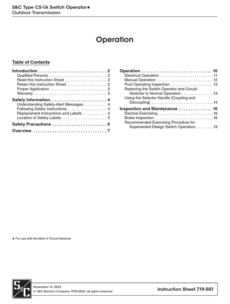
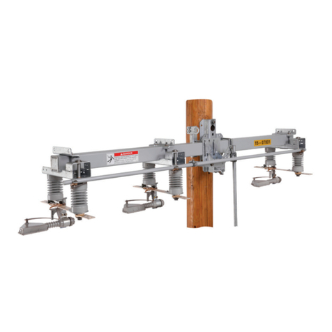
S&C Mark VI User manual

June 11, 2012© S&C Electric Company Instruction Sheet 712-501
S&C Circuit-Switchers — Mark VI
Outdoor Transmission (69 kV through 138 kV)
Operation
Table of Contents
Section Page Section Page
Introduction
Qualified Persons..............................2
Read this Instruction Sheet ......................2
Retain this Instruction Sheet .....................2
Proper Application .............................2
Warranty .....................................2
Safety Information
Understanding Safety-Alert Messages .............3
Following Safety Instructions .....................3
Replacement Instructions and Labels ..............3
Location of Safety Labels and Tags................4
Safety Precautions.............................. 5
Indicators
Circuit-Switcher Position Indication ................6
Understanding the Interrupter Indicators ............7
Understanding the Gas-Pressure Gauge ...........8
Understanding the Remote Gas-Density Indicator ...10
Switch Operation
Before Operating ............................. 11
Closing the Circuit-Switcher..................... 12
Opening the Circuit-Switcher .................... 13
Opening the Circuit-Switcher Using the
Optional Manual Trip Device .................. 15
Inspection Recommendations
Recommended Inspection Procedures ............ 18
Using the Manual Operating Handle to Operate the
Disconnect During Inspection ................. 19
Coupling and Decoupling the Switch Operator for
Inspection ................................21
Inspecting the Operation of Circuit-Switcher Blades and
Blade Contacts. ............................24
Inspecting the CS-1A Switch Operator Motor Brake ..26
Guidelines for Interrupter Resistance Values .......26

2S&C Instruction Sheet 712-501
Introduction
Qualified Persons ÇWARNING
The equipment covered by this publication must be installed, operated, and maintained
by qualified persons who are knowledgeable in the installation, operation, and main-
tenance of overhead electric power distribution equipment along with the associated
hazards. A qualified person is one who is trained and competent in:
• The skills and techniques necessary to distinguish exposed live parts from non-live
parts of electrical equipment.
• The skills and techniques necessary to determine the proper approach distances
corresponding to the voltages to which the qualified person will be exposed.
• The proper use of the special precautionary techniques, personal protective equip-
ment, insulating and shielding materials, and insulated tools for working on or near
exposed energized parts of electrical equipment.
These instructions are intended only for such qualified persons. They are not
intended to be a substitute for adequate training and experience in safety procedures
for this type of equipment.
Read this
Instruction Sheet
Read this instruction sheet thoroughly and carefully before installing or operating your
S&C Circuit-Switcher—Mark VI. Familiarize yourself with “SAFETY INFORMATION” on
pages 3 and 4. The latest version of this publication is available online in PDF format at
www.sandc.com. Support/Product Literature Library.
Retain this
Instruction Sheet
This instruction sheet is a permanent part of your S&C Circuit-Switcher—Mark VI. These
instructions should be stored in the Mark VI CS-1A Switch Operator using the instruction
manual holder.
Proper Application ÇCAUTION
The equipment in this publication is only intended for use in switching and protection
of capacitor banks and substation transformers. The application must be within the
ratings furnished for the equipment. Ratings for the Mark VI Circuit-Switcher are listed
on the ratings label on the side of the Mark VI CS-1A Switch Operator.
Warranty The warranty and/or obligations described in S&C’s standard conditions of sale, as set
forth in Price Sheet 150, plus any special warranty provisions, as set forth in the applicable
product-line specification bulletin, are exclusive. The remedies provided in the former for
breach of these warranties shall constitute immediate purchaser’s or end user’s exclusive
remedy and a fulfillment of all seller’s liability. In no event shall seller’s liability to imme-
diate purchaser or end user exceed the price of the specific product which gives rise to
immediate purchaser’s or end user’s claim. All other warranties whether express or implied
or arising by operation of law, course of dealing, usage of trade or otherwise, are excluded.
The only warranties are those stated in Price Sheet 150, and THERE ARE NO EXPRESS
OR IMPLIED WARRANTIES OF MERCHANTABILITY OR FITNESS FOR A PARTICULR
PURPOSE. ANY EXPRESS WARRANTY OR OTHER OBLIGATION PROVIDED IN PRICE
SHEET 150 IS GRANTED ONLY TO THE IMMEDIATE PURCHASER AND END USER,
AS DEFINED THEREIN. OTHER THAN AN END USER, NO REMOTE PURCHASER MAY
RELY ON ANY AFFIRMATION OF FACT OR PROMISE THAT RELATES TO THE GOODS
DESCRIBED HEREIN, ANY DESCRIPTION THAT RELATES TO THE GOODS, OR ANY
REMEDIAL PROMISE INCLUDED IN PRICE SHEET 150.
The seller’s warranties are contingent upon the installation and adjustment of Mark VI
Circuit-Switcher in accordance with S&C’s applicable instructions sheets, data sheets,
and/or data bulletins.
S&C Instruction Sheet 712-501 3
Safety Information
Understanding
Safety-Alert
Messages
There are several types of safety-alert messages which may appear throughout this
instruction sheet as well as on labels and tags attached to the Mark VI Circuit-Switcher.
Familiarize yourself with these types of messages and the importance of the various sig-
nal words, as explained below.
ÇDANGER
“DANGER” identifies the most serious and immediate hazards which will likely result
in serious personal injury or death if instructions, including recommended precau-
tions, are not followed.
ÇWARNING
“WARNING” identifies hazards or unsafe practices which can result in serious personal
injury or death if instructions, including recommended precautions, are not followed.
ÇCAUTION
“CAUTION” identifies hazards or unsafe practices which can result in minor personal
injury or product or property damage if instructions, including recommended precau-
tions, are not followed.
NOTICE
“NOTICE” identifies important procedures or requirements that, if not followed, can
result in product or property damage if instructions are not followed.
Following
Safety Instructions
If you do not understand any portion of this instruction sheet and need assistance, contact
your nearest S&C Sales Office or S&C Authorized Distributor, or call S&C Headquarters at
(773) 338-1000, Monday through Friday between 8:30 AM and 5:00 PM Central Standard
Time. (In Canada, call S&C Electric Canada Ltd. at (416) 249-9171, Monday through Fri-
day between 8:00 AM and 5:00 PM Eastern Standard Time.)
NOTICE
Read this instruction sheet thoroughly and
carefully before installing or operating your
S&C Circuit-Switcher—Mark VI.
Replacement
Instructions and
Labels
If you need additional copies of this instruction sheet, contact your nearest S&C Sales
Office, S&C Authorized Distributor, S&C Headquarters, or S&C Electric Canada Ltd.
It is important that any missing, damaged, or faded labels on the equipment be
replaced immediately. Replacement labels are available by contacting your nearest S&C
Sales Office, S&C Authorized Distributor, S&C Headquarters, or S&C Electric Canada Ltd.

4S&C Instruction Sheet 712-501
Reorder Information for Safety Labels
Location Safety-Alert Message Description Part Number
AÇWARNING Use push button control to open or close . . . G-9025
BÇWARNING DO NOT operate the Circuit-Switcher with . . . G-9024
CÇWARNING DO NOT disassemble or modify . . . G-7015-5
DÇCAUTION Unauthorized changes should not be made . . . G-9027
EÇCAUTION DO NOT operate the Circuit-Switcher with . . . G-9026
Safety Information
Location of Safety Labels and Tags
B
C
D
E
DO NOT operate the Circuit-Switcher with the manual
operating handle.The manual operating handle is
only intended for use during checkout of the
Circuit-Switcher when the Circuit-Switcher is
de-energized and isolated.
SERIOUS INJURY and damage to the Circuit-Switcher
may result if the manual operating handle is used
to operate the Circuit-Switcher.
G-9026
ÇCAUTION
G-9024
Ç
WARNING
DO NOT operate the Circuit-Switcher with the manual operating handle.
The manual operating handle is only intended for use during checkout
of the Circuit-Switcher when the Circuit-Switcher is de-energized and
isolated. Serious injury and damage to the Circuit-Switcher may
result if the manual operating handle is used to operate the Circuit-
Switcher.
CHICAGO, ILLINOIS 60626
A

S&C Instruction Sheet 712-501 5
ÇDANGER
S&C Mark VI Circuit-Switchers operate at high voltage. Failure to observe
the precautions below will result in serious personal injury or death.
Some of these precautions may differ from company operating procedures and
rules. Where a discrepancy exists, users should follow their company’s operating
procedures and rules.
1. QUALIFIED PERSONS. Access to substation
switching equipment must be restricted only to quali-
fied persons. See “Qualified Persons” on page 2.
2. SAFETY PROCEDURES. Always follow safe
operating procedures and rules.
3. PERSONAL PROTECTIVE EQUIPMENT. Always
use suitable protective equipment such as rubber
gloves, rubber mats, hard hats, safety glasses, and flash
clothing in accordance with safe operating procedures
and rules.
4. SAFETY LABELS AND TAGS. Do not remove or
obscure any of the “DANGER,” “WARNING,”
“CAUTION,” “NOTICE,” or labels and tags. Remove
tags ONLY if instructed to do so.
5. ENERGIZED COMPONENTS. Always consider all
parts live until de-energized, tested, and grounded.
6. CIRCUIT-SWITCHER POSITION. Always confirm
the open/close position of Circuit-Switcher by visually
observing the position of the indicators underneath
each interrupter. See pages 6 and 7. Switches may be
energized from either side.
7. MAINTAINING PROPER CLEARANCE. Always
maintain proper clearance from energized
components.
8. OPERATION. Circuit making and breaking is involved
in the normal operation of this interrupter switch and,
as a result, “partway” opening or closing is undesirable.
To operate, follow the operating procedure as outlined
in this Instruction Sheet.
Safety Precautions

6S&C Instruction Sheet 712-501
Circuit-Switcher Position Indication
Circuit-Switcher position can be determined in
one of three ways:
a. Locally, by visually verifying the position of
the integral disconnect. See Figure 1.
b. Locally, via position-indicating lamps on the
Mark VI CS-1A Switch Operator (if fur-
nished). See Figure 2.
c. Remotely, via auxiliary position-indication
contacts furnished with the Circuit-
Switcher.
Circuit-Switchers may be in one of two
positions:
Open: The integral disconnect will be open and
the interrupters will be closed.
Closed: The integral disconnect will be closed
and the interrupters will be closed.
See the section titled “Understanding the
Interrupter Indicators” starting on page 7
for details on the function of the interrupter
indicators.
NOTICE
The interrupter indicators only indicate
the state of the interrupter contacts, and
DO NOT indicate the state of the entire
Circuit-Switcher. Verify the position of the
disconnect blades to determine the “OPEN”
or “CLOSED” status of the Circuit-Switcher.
Figure 1. Mark VI Circuit-Switcher with blades in the OPEN position.
Disconnect blades
Figure 2. Location of position-indicating lamps.
Position indicating lamps
Indicators

S&C Instruction Sheet 712-501 7
Indicators
Understanding the
Interrupter Indicators
An indicator is located on the underside of each
interrupter. The indicators are not meaning-
ful while the interrupters are being closed
and charged. Wait for the interrupter charging
motors to cease operation before checking
indicator position. The interrupters will be
automatically closed and charged following an
opening operation.
If the interrupter is “CLOSED and
CHARGED,” the indicator reads “CLOSED.”
See Figure 3.
If the interrupter is “OPEN and DIS-
CHARGED,” the indicator reads “OPEN.” See
Figure 4.
During normal operation, the interrupter
indicators will only read “OPEN” for a brief
moment after the interrupters have tripped—
before the interrupter charging motors begin
closing and charging the interrupters. If the
manual trip device (Catalog Number Suf-
fix “-T”) is furnished, the interrupters will
read “OPEN” after a manual trip operation.
Refer to the instructions for using the manual
trip device in Steps 8 through 10 starting on
page 15.
Figure 3. The interrupter is “CLOSED and CHARGED.” The indicator
reads “CLOSED.”
Figure 4. The interrupter is “OPEN and DISCHARGED.” The indicator
reads “OPEN.”
“OPEN and DISCHARGED”
“CLOSED and CHARGED”

8S&C Instruction Sheet 712-501
Understanding the
Gas-Pressure Gauge
A temperature-compensated gas-pressure gauge
is located on the underside of each interrupter.
It shows whether SF6gas density is sufficient
for a trip operation. The gas-pressure gauge
shows three zones:
OK TO OPERATE:
This is the white zone. If the gauge needle is in
this zone, the pole-unit is at normal gas density
and can be opened and closed. See Figure 5.
OK TO OPERATE (BUT REPLACE):
This is the yellow zone. If the gauge needle is
in this zone, the interrupter can be opened and
closed with full ratings. However, the inter-
rupter has lost gas and should be replaced as
soon as possible. See Figure 6.
“OK TO OPERATE
(BUT REPLACE)” zone
Figure 5. Gauge needle in white “OK TO OPERATE” zone.
Figure 6. Gauge needle in yellow “OK TO OPERATE (BUT REPLACE)”
zone.
“OK TO OPERATE” zone
Indicators

S&C Instruction Sheet 712-501 9
Indicators
REPLACE:
There are two red zones. If the indicator needle
is in the red zone shown in Figure 7, the gas
density in the interrupter has dropped below the
minimum functional level and the interrupter
will not maintain full interrupting or dielectric
ratings. The interrupter should be removed from
service and replaced promptly. Do not operate
the Mark VI Circuit-Switcher.
If the indicator needle is in the red zone
shown in Figure 8, the local gas-density gauge
is damaged, and cannot be relied on to pro-
vide an accurate indication of gas density.
The pole-unit should be removed from service
and replaced promptly. Contact your local
S&C Sales Office. Do not operate the Mark VI
Circuit-Switcher.
NOTICE
At temperatures below -31°F (-35°C), the
indicator needle will be in the red zone due
to the cold temperature. The gas density is
below the minimum functional level, so the
interrupter will not have full interrupting or
dielectric ratings. At these temperatures,
the gas-pressure gauge does not pro-
vide accurate indication of whether an
interrupter is losing SF6.
Figure 7. Gauge needle in red “REPLACE”zone.
“REPLACE” zone
Figure 8. Gauge needle in red “REPLACE”zone.
“REPLACE” zone

10 S&C Instruction Sheet 712-501
Understanding the
Remote Gas-Density Indicator
If furnished, the remote gas-density indicator
provides contacts for each interrupter that
allow remote monitoring of two low-gas-pres-
sure alarms:
Level 1 Alarm:
When a Level 1 Alarm is issued, the interrupter
can be opened and closed as usual. However,
the interrupter has lost gas and should be
replaced as soon as possible.
The remote gas-density Level 1 alarm con-
tact opens at 93% of normal density, or 70 PSIG
at 68°F (20°C). Contacts are normally closed at
normal operating gas pressure.
Level 2 Alarm:
When a Level 2 Alarm is issued, the gas density
in the interrupter has dropped below the mini-
mum functional level. The interrupter will not
maintain full interrupting or dielectric ratings.
The interrupter should be removed from service
and replaced promptly. DO NOT operate this
Mark VI Circuit-Switcher.
The remote gas-density Level 2 alarm con-
tact opens at 88% of normal density, or 65 PSIG
at 68° (20°C). Contacts are normally closed at
normal operating gas pressure.
NOTICE
At temperatures below -31°F (-35°C), a
Level 2 Alarm may be issued due to the cold
temperature. At such low temperatures, gas
density is below the interrupter’s minimum
functional level, so the interrupter will not
have full interrupting or dielectric ratings.
At these temperatures, a Level 2 Alarm
does not accurately indicate whether an
interrupter is losing SF6.
Indicators

S&C Instruction Sheet 712-501 11
Switch Operation
Before Operating
Step 1
Before operating the Mark VI Circuit-Switcher:
a. Check the internal decoupling mechanism
inside the Mark VI CS-1A Switch Operator
to verify that the selector handle is in the
“COUPLED” position. See Figure 9.
b. Check that the manual operating handle is
in the storage position, and tagged or pad-
locked. See Figure 10.
c. Check that the two-pole pull-out fuseholder
for the motor (and space heater, if fur-
nished) is inserted. See Figure 11.
d. Check that the switch operator enclosure
door is tagged and padlocked in accordance
with standard system operating
procedures.
Figure 9. Position indexing drums.
Figure 10. Manual operating handle tagged and/or padlocked.
Figure 11. Check that the motor circuit fuseholder is in place.
Internal decoupling mechanism
(in coupled position)
Motor circuit fuseholder
Padlock or tag

12 S&C Instruction Sheet 712-501
Closing the Circuit-Switcher
When a “CLOSE” signal is received by the switch
operator, the disconnect will close, closing the
circuit.
Step 2
Verify that each interrupter is “CLOSED” and the
gas-pressure gauge is in the “OK TO OPERATE”
zone. See Figure 12. Verify that the Circuit-
Switcher disconnect is open.
Step 3
Lift the push button protective cover of the
Mark VI CS-1A Switch Operator. For Circuit-
Switchers with the optional remote-control
blocking switch (Catalog Number Suffix “-Y”),
opening the push button protective cover pre-
vents remote operation of the switch operator.
See Figure 13.
Step 4
To close the Circuit-Switcher:
a. Press the “CLOSE” push button for about
one second. See Figure 13.
b. If the CLOSE push button has not been fur-
nished (Catalog Number Suffix “-J”), send a
user-furnished “CLOSE” signal to the
operator.
The Circuit-Switcher disconnect blades will
close, restoring the circuit.
Ç
WARNING
DO NOT operate the Mark VI Circuit-
Switcher with the manual operating handle
while the switch is energized. The manual
operating handle should only be used
during installation and checkout of the
switch. Manual operation of an ener-
gized Mark VI Circuit-Switcher could,
in the event of a fault or loss of control
power to the operator, cause serious
injury or death as well as damage to the
Circuit-Switcher.
Figure 12. Interrupter is “CLOSED and CHARGED.” The indicator reads
“CLOSED.”The gas-pressure gauge needle is in the white “OK TO OPER-
ATE” zone.
Figure 13. Lift the push button protective cover, and press the “CLOSE”
push button.
“CLOSED and CHARGED” “OK TO OPERATE” zone
CLOSE push button
Remote-control
blocking switch
Switch Operation

S&C Instruction Sheet 712-501 13
Switch Operation
Opening the Circuit-Switcher
When the switch operator receives a “OPEN”
signal, the interrupters will trip, clearing the
circuit. The disconnect will then open, provid-
ing a visible gap. Once the disconnect is fully
open, the interrupter charging motors will reset
the interrupters. Charging takes approximately
two minutes.
Step 5
Verify that each interrupter is “CLOSED” and the
gas-pressure gauge is in the “OK TO OPERATE”
zone. See Figure 14.
NOTICE
Visually verify the disconnect position to
determine the “OPEN” or “CLOSED” status
of the Circuit-Switcher. The interrupter
indicators only indicate the state of the
interrupter contacts, and DO NOT indi-
cate the state of the entire Circuit-Switcher.
Step 6
Lift the push button protective cover of the
Mark VI CS-1A Switch Operator. For Circuit-
Switchers with the optional remote-control
blocking switch (Catalog Number Suffix “-Y”),
opening the push button protective cover pre-
vents remote operation of the switch operator.
See Figure 15.
Step 7
To trip the Circuit-Switcher:
a. Press the “OPEN” push button for about one
second. See Figure 15.
b. If an “OPEN” push button has not been fur-
nished (Catalog Number Suffix “-J”), send a
user-furnished “OPEN” signal to the
operator.
Ç
WARNING
DO NOT operate the Mark VI Circuit-
Switcher with the manual operating handle
while the switch is energized. The manual
operating handle should only be used
during installation and checkout of the
switch. Manual operation of an ener-
gized Mark VI Circuit-Switcher could,
in the event of a fault or loss of control
power to the operator, cause serious
injury or death as well as damage to the
Circuit-Switcher.
Figure 14. Interrupter is “CLOSED AND CHARGED.”The interrupter reads
“CLOSED.” Gauge needle is in the white “OK TO OPERATE” zone.
Figure 15. Lift the push button protective cover, and press the “OPEN”
push button.
OPEN push button
CLOSED and CHARGED
Remote-control
blocking switch
“OK TO OPERATE” zone

14 S&C Instruction Sheet 712-501
The interrupters will trip, and the blades
will open, clearing the circuit. After each trip
operation, the interrupter charging motors
will close and charge the interrupter contacts,
readying the interrupters for a close operation.
It is recommended that the operator (or con-
trol circuit setting) wait five minutes between
OPEN and CLOSE operations.
NOTICE
DO NOT disconnect control power while
the Mark VI Circuit-Switcher interrupter
charging motors are operating. The inter-
rupter charging motors will reset to the
beginning of the charging cycle when con-
trol power is restored which may cause the
operation of the blade and interrupter to
become unsynchronized. If control power
is lost during switch operation, contact your
local S&C Sales Office.
Switch Operation

S&C Instruction Sheet 712-501 15
Switch Operation
Tripping the Circuit-Switcher Using
the Optional ManualTrip Device
If furnished, the manual trip device will be
located on a swing out panel inside the Mark VI
CS-1A Switch Operator.
When tripping the Mark VI Circuit-Switcher
using the optional manual trip device (Catalog
Number Suffix “-T”) the interrupters will trip,
clearing the circuit, but the disconnect will not
open. DO NOT manually open the disconnect
with the manual operating handle. If available,
use a secondary-side disconnect to isolate the
Mark VI Circuit-Switcher to create a visible
gap. Contact your local S&C Sales Office for
more information.
ÇCAUTION
DO NOT operate the Mark VI Circuit-
Switcher disconnect with the manual
operating handle while using the manual trip
device. Manual operation of the Mark VI
Circuit-Switcher disconnect could cause
a loss of electrical coordination between
the interrupters and disconnect.
Step 8
Verify that each interrupter is “CLOSED” and the
gas-pressure gauge is in the “OK TO OPERATE”
zone. See Figure 16.
NOTICE
Verify the disconnect blade position to
determine the “OPEN” or “CLOSED” status
of the Circuit-Switcher. The interrupter
indicators only indicate the state of the
interrupter contacts, and DO NOT indi-
cate the state of the entire Circuit-Switcher.
Step 9
Remove the two-pole pull-out fuseholder for
the motor (and space heater, if furnished). See
Figure 17.
Figure 16. The interrupter is “CLOSED AND CHARGED.” The interrupter
reads “CLOSED.” Gauge needle is in the white “OK TO OPERATE” zone.
Motor circuit fuseholder
Figure 17. Remove the motor circuit fuseholder.
CLOSED and CHARGED “OK TO OPERATE” zone

16 S&C Instruction Sheet 712-501
Figure 19. The interrupter is “OPEN and DISCHARGED.” The indicator
reads “OPEN.”
Step 10
To trip the Circuit-Switcher with the manual
trip device:
a. Crank the manual-trip device handle to trip
the Mark VI Circuit-Switcher interrupters.
Crank the handle between 5 and 10 times.
The red LED will start flashing when the
manual-trip device is fully charged.
b. Then press the manual-trip push button
located underneath the manual-trip device
for about one second. The standard local-
trip push button is disabled when control
power is not present. The manual-trip
device only retains its charge for about five
minutes, so press the push button promptly.
See Figure 18.
c. All three interrupters will open simulta-
neously. The disconnect WILL NOT open.
Check that all three interrupters are “OPEN”
and “DISCHARGED.” See Figure 19.
Figure 18. Operate the manual-trip device.
Red LED
“OPEN and DISCHARGED”
Trip device handle
Manual trip
push button
Switch Operation

S&C Instruction Sheet 712-501 17
Switch Operation
Figure 20. Push the local-trip push button or send a user-furnished
“OPEN” signal.
“OPEN” push button
d. When control power is restored, lift the
push button protective cover of the Mark VI
CS-1A Switch Operator.
e. Then press the “OPEN” push button, located
on the front of the Mark VI CS-1A Switch
Operator, for about one second, or send a
remote trip signal to the operator. See Fig-
ure 20. The disconnect will open, and the
charging motors will begin charging the
interrupters. Charging takes approximately
two minutes.

18 S&C Instruction Sheet 712-501
Inspection Recommendations
To ensure Mark VI Circuit-Switcher’s continued proper
performance, it should be inspected in accordance with
the recommended schedule and procedures contained
in the tables in S&C Data Bulletin 712-90, Inspection
Recommendations.
RECOMMENDED INSPECTION PROCEDURES FOR S&C CIRCUIT-SWITCHER COMPONENTS
Component Inspection Procedures
General
1. Check with your local S&C Sales Office for any outstanding Field Notifications for inspection, retrofit, or maintenance on
your model switch.
2. Check the switch for overall cleanliness of the insulators, live parts, and operator. Power washing with water or a
non-abrasive cleaning method should be performed for severe contamination. Reapply lubricant to the live parts after
washing.
Switch Operator
1. Check for evidence of water ingress, damage, excessive corrosion, or wear.
2. Check ease of operation during slow, manual cranking using the switch operator manual operating handle.
3. Check electrical operation, coupled and decoupled.
4. Check for loose wiring inside enclosure and proper functioning of position-indicating lamps, operation counter, conve-
nience lamp, etc.
5. Check operation of brake and readjust if necessary.
Power Train
1. Check for evidence of damage, excessive corrosion, or wear.
2. Check tightness of fasteners.
3. Observe operation during slow, manual cranking using the switch operator manual operating handle. Check for complete
stroking of the various drive levers against their stops and for attainment of overtoggle positions, as required.
4. Check condition of seals.
Interrupter1
1. Check for low gas density (indicator underneath interrupter).
2. Check tightness of fasteners on current-carrying parts.
3. Check for discoloration, contamination, or other damage to the interrupter insulation.
4. Check for excessive corrosion at the terminal pad and interrupter-to-disconnect bus.
5. Check for evidence of excessive terminal-pad loading.
Charging Motor 1. Check for evidence of water ingress, damage, excessive corrosion, or wear.
2. Check tightness of fasteners—especially at the connection between the motor and the interrupter operating shaft.
Disconnect
Live Parts
1. Check for evidence of damage, excessive corrosion, or wear—especially at the fault-closing contacts and current-carrying
contacts. Replace current-carrying jaw contacts if the silver-alloy inserts on two or more contact fingers are worn to the
extent that the blade tongue contact engages the full width of the contact finger.
2. Check tightness of fasteners on current-carrying parts.
3. Observe operation of disconnect during slow, manual cranking using the switch operator manual operating handle. Check
for proper contact alignment.
4. Lubricate the contact surfaces with an appropriate lubricant.2
5. Check for excessive corrosion at the terminal pad and interrupter-to-disconnect bus.
6. Check for evidence of excessive terminal-pad loading.
Pre-Insertion Inductor
1. Clean the exterior of inductor windings using a nontoxic, nonflammable solvent.
2. Touch up exterior finish of inductor windings with an appropriate silicone-alkyd paint, such as ALMA AP-9753.
3. Check moving and stationary arcing rods for proper setting and for evidence of damage and excessive corrosion or wear.
Grounding Switch
1. Check for evidence of damage, excessive corrosion, or wear—especially at the jaw-contact members.
2. Check tightness of fasteners on current-carrying parts.
3. Observe operation using manual operating handle. Check for proper contact alignment.
4. Lubricate the contact surfaces with an appropriate lubricant.2
1Mark VI Circuit-Switcher interrupters should have resistance values
under 200 micro-ohms when new, and under 500 micro-ohms when in
service. If an interrupter has a resistance value outside this range, contact
your local S&C Sales Office.
2Shell Gadus® S2 U1000 2 Lubricant, Catalog Number 9999-043 is
available in 1 oz. tubes from S&C. Shell Darina SD2, Dow 33, or equivalent
can be substituted.

S&C Instruction Sheet 712-501 19
Inspection Recommendations
Using the Manual Operating
Handle to Operate the Disconnect
During Inspection
Ç
WARNING
DO NOT operate the Mark VI Circuit-
Switcher with the manual operating handle
while the switch is energized. The manual
operating handle should only be used during
installation, inspection, and checkout of the
switch. Manual operation of an energized
Mark VI Circuit-Switcher could, in
the event of a fault or loss of control
power to the operator, cause serious
injury or death as well as damage to the
Circuit-Switcher.
Step 11
Verify that the CS-1A Switch Operator is in the
“COUPLED” or “DECOUPLED” position by
looking at the internal decoupling mechanism
inside the Mark VI CS-1A Switch Operator. See
Figures 21 and 22. If the switch operator is
“DECOUPLED,” operating the manual handle
will only operate the motor inside the Mark VI
CS-1A Switch Operator—the disconnect will
remain in its starting position and the inter-
rupter trip and close circuits are disabled. If the
operator is in the “COUPLED” position, operat-
ing the manual operating handle will cause the
disconnect blades to open. DO NOT operate
an energized Circuit-Switcher with the manual
operating handle. The interrupters will not trip
when using the manual operating handle to open
the disconnect.
Step 12
Remove the two-pole pull-out fuseholders for
the motor (and space heater, if furnished). See
Figure 23.
Figure 21. CS-1A Switch Operator in the decoupled position.
Selector
handle
(in decoupled
position)
Internal decoupling
mechanism
(in decoupled position)
Motor circuit fuseholder
Figure 23. Remove the motor circuit.
Figure 22. CS-1A Switch Operator in decoupled position.
Internal decoupling mech-
anism (in coupled position)

20 S&C Instruction Sheet 712-501
Step 13
Pull the latch knob on the hub of the manual
operating handle and pivot the handle forward
slightly from its storage position. Release the
latch knob while continuing to pivot the handle
forward to lock it into the cranking position.
See Figure 24.
Step 14
Crank the manual operating handle on the
Mark VI CS-1A Switch Operator until the dis-
connect blade is in the fully “OPEN” or fully
“CLOSED” position. Visually inspect the blade
on all three phases to confirm the Circuit-
Switcher is open or closed. The switch operator
position indicator, seen through the observation
window, will also show when the approximate
open or closed position has been attained.
Step 15
After performing your inspection or mainte-
nance, manually operate the Circuit-Switcher
disconnect blade to its starting position (open or
closed). The switch operator position indicator,
seen through the observation window, will show
when the approximate open or closed position
of the disconnect has been attained.
Step 16
Pull the latch knob on the hub of the manual
operating handle and pivot it back into its
storage position. Release the latch and padlock
or tag the handle in accordance with standard
system operating procedures.
Step 17
Replace the two-pole pull-out fuseholders for
one motor (and space heater if furnished).
Figure 24. Use the manual operating handle to operate the disconnect.
Manual
operating
handle
Latch knob
Selector handle
(in coupled
position)
Inspection Recommendations
Other manuals for Mark VI
1
Table of contents
Other S&C Switch manuals

S&C
S&C Omni-Rupter User manual

S&C
S&C 2000 series User manual

S&C
S&C Alduti-Rupter Switches Outdoor Distribution Owner's manual

S&C
S&C 2000 series Owner's manual

S&C
S&C Vista SD User manual

S&C
S&C Alduti-Rupter User manual

S&C
S&C 2000 series User manual

S&C
S&C 2000 series Owner's manual

S&C
S&C 2000 series User manual

S&C
S&C Mark V User manual

S&C
S&C Alduti-Rupter Operation and maintenance manual

S&C
S&C Alduti-Rupter Owner's manual

S&C
S&C 6801M User manual

S&C
S&C Omni-Rupter User manual

S&C
S&C Alduti-Rupter Programming manual

S&C
S&C Vista SD User manual

S&C
S&C Omni-Rupter Series Owner's manual

S&C
S&C AS-1A Guide

S&C
S&C Alduti-Rupter User manual

S&C
S&C CS-1A User manual