7
INSTALLATION
1.2 Installation
1.2.1 Location/Position
The location of the switch can greatly affect its performance. Consider these guidelines before
placement, connection and operation.
• Choose a location that complies with the acceptable temperature and humidity ranges listed
in the Specications section.
• Avoid placing the switch in the vicinity of strong electromagnetic eld generators (such as
motors), vibration, dust and direct sunlight.
• Allow at least 10 cm of space at the front and rear of the unit for ventilation.
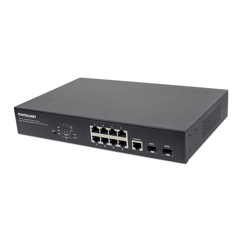
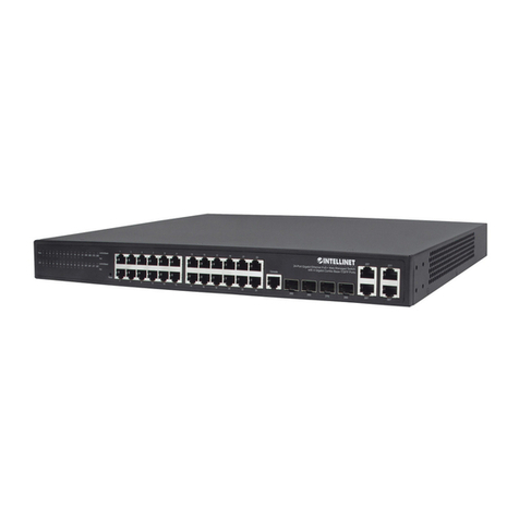
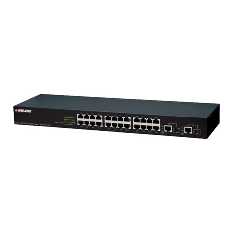
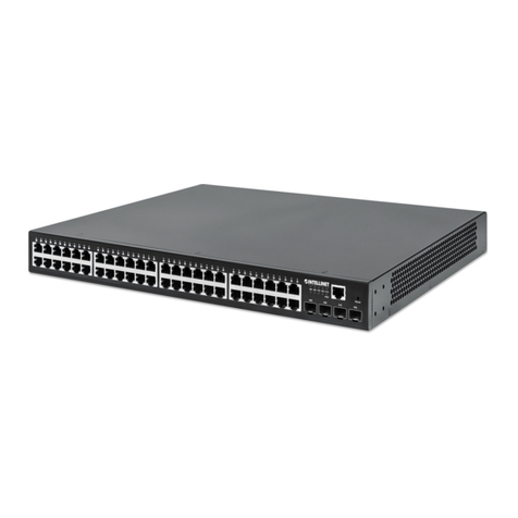
• As the switch is capable of connecting up to 28 network devices employing a combination of
twisted-pair and ber cabling paths, check that all cords/connectors can be safely secured.
You have three options for positioning the switch:
• For desktop use, choose a clean, at surface with convenient access to an AC power outlet
and afx the four included self-adhesive rubber pads to the bottom of the unit.
• For vertical mounting, use the underside of the switch as a template to measure and mark out
the position of the holes on the vertical surface where the unit is to be installed. Then use the
two screws provided to mount the switch rmly in place.
• For rack mounting, attach brackets to each side of the switch and place the brackets in the
rack’s slots. Insert and tighten two screws to secure the bracket to the rack on each side.
1.2.2 Powering On the Unit
The switch uses an AC power supply: 100–240 V AC / 50–60 Hz; or -48 V DC. The power on/
off switch is located at the rear of the unit, adjacent to the AC power connector and the system
fans. The switch’s power supply automatically self-adjusts to the local power source, and may
be powered on without having any or all LAN segment cables connected.
1. Plug the power cable directly into the receptacle located at the back of the device.
2. Plug the power adapter into an available socket. NOTE: For international use, you may need
to change the AC power adapter cord. Use only a power cord set that has been approved
for the receptacle type and electrical current in the country you’re in.
3. Check the front-panel LEDs as the device is powered on to verify that the PWR LEDs are
lit. If they’re not, check that the power cable is correctly and securely plugged in.
WarNiNg: Because invisible laser radiation may be emitted from the aperture of the
ports when no cable is connected, avoid exposure to laser radiation and do not stare
into open apertures.
Port LED Condition Status
10/100 On (green) Port operating at 100 Mbps
(copper) Off Port operating at below 100 Mbps
ACT On (green) Illuminated when connectors are attached
Flashing (green) Data trafc passing through port
Off No valid link established on port
A 25-28 On (green) Illuminated when connectors are attached
Gigabit E’net Flashing (green) Data trafc passing through port
Off No valid link established on port
B 25-28 On (green) Port is operating at 10 Mbps. If LED C is also on, port is
Gigabit E’net operating at 1000 Mbps
Off If LED C is on, port is operating at 100 Mbps or link is down
C 25-28 On (green) Port is operating at 100 Mbps. If LED B is also on, port is
Gigabit E’net operating at 1000 Mbps
Off If LED B is on, port is operating at 10 Mbps or link is down
