Sanderson Teleporter Administrator guide

Marconi Sailing Club Ltd. MSCP83
Issue 2
Sanderson Teleporter Instructions & Code of Practice 21/03/2014
Page 1 of 17
Guidance notes for authorised Teleporter drivers
Contents
1. Introduction
2. Safety
3. Teleporter and attachments - a guide to their use
Appendix 1 –Communication and Signalling
Appendix 2 –Maximum Load Capacity
1. Introduction.
With ever increasing awareness of the need to prevent accidents, the potential for action
against Clubs or club members and the increasing interest being taken by the relevant
authorities in the prevention of accidents, it is incumbent on sailing clubs and their members
to examine their working practices and so far as is practicable minimise or eliminate
potential hazards.
Members, in any event, would wish to maintain high safety standards within Marconi Sailing
Club and it is for this reason the following guidance notes are issued. They should not be
considered to be all embracing, but rather to form the basis for good practice. It is up to
each member to ensure that the operations in which they are engaged are safely carried
out.
These instructions do not apply to or consider the ‘ At Work Situation’ where any individual
is carrying out the activity for hire or reward.
The instructions address two principal areas:
1. The use of safe working practices in order to ensure the safety of persons in the
immediate area of activity including where appropriate the adjacent waters.
2. The correct use of equipment to ensure it remains in good working order and which may
directly or indirectly contribute towards safety.
The Sanderson Teleporter and its attachments may only be driven by those
specifically trained.
2. Safety.
In all operations involving the use of the Teleporter the following will apply:
a) The Teleporter must be suitable for the intended task.
b) The Teleporter driver must assess the intended task and has the right to refuse to
use it where the safety of doing so is in doubt.

Marconi Sailing Club Ltd. MSCP83
Issue 2
Sanderson Teleporter Instructions & Code of Practice 21/03/2014
Page 2 of 17
2. Safety (Cont)
c) When an Officer of the Day is on duty at the time of Teleporter activity that person
must be informed that Teleporter operations are in progress.
d) The seat belt MUST be worn at all times during operation and is in good condition
and functions correctly.
e) Prior to use the following safety checks should be carried out-
The attachment to be used is correct (see list under “Attachments” heading) for
the task.
The tyres (and in particular the front tyres) are inflated to the correct pressure. If
the front tyres are to be checked it is important to ensure that Schrader valve is
at the top of the rim before checking as the tyres are ballasted. (80% filled with
water)
The hydraulic fluid level is correct.
f) The Teleporter driver must always ensure that the intended load does not exceed
the “Safe Working Load” as detailed on the plate inside the driver’s door. The “Safe
Working Load” is the maximum weight that can be transported at each lift
depending on the following variable circumstances:
The Maximum Load Capacity –is shown in the Appendix 2 and on Load Plate
inside the cab door. This will vary with Reach and Lift heights as shown on the
graph
Attachments –are added to the Carriage and thereby become part of the load.
This weight must be taken from the load weight when calculating the safe
working load. The weight of each attachment is stamped on the Attachment
plate (together with the load capacity of that particular attachment). If the
Attachment load capacity is less than the calculated safe working load for the
Teleporter then, the Attachment load capacity becomes the actual safe working
load.
Terrain –being the surface on which the load will be carried –affects the safe
working load by its conditions in relation to maintaining stability.
Gradient –is the angle or incline of the terrain, which by its severity could affect
the safe working load in relation to maintaining stability.

Marconi Sailing Club Ltd. MSCP83
Issue 2
Sanderson Teleporter Instructions & Code of Practice 21/03/2014
Page 3 of 17
2. Safety (Cont)
Note:
To prevent any potential overload a “Safe Load Indicator” is fitted to the Teleporter
and an alarm will sound when the load exceed the maximum. However, a competent
operator should always be able to estimate when the load is safe and should not wait
to hear the alarm.
If the “Safe Load Indicator” is not functioning correctly refer to the Tractor Coordinator
and enter the detail in the Teleporter Logbook. (stored in the cab)
The detailed functionality of the “Safe Load Indicator” is shown in Appendix 3
h) Before operations commence the Teleporter driver must ensure that one responsible
person has been nominated as Banksman and that clear lines of communication
using hand signals as defined in Appendix 1 have been established. This is
particularly important when reversing, as visibility on the rear right side is restricted. A
Banksman may not be required for all operations and the driver must decide if one is
necessary for the task to be performed. A Banksman is always required when
loading/unloading and handling moorings anywhere on the club site or when working
in confined spaces.
i) The Teleporter must only be used to tow a boat or equipment if it is absolutely
necessary in an emergency.
j) Slinging –The “Crane Jib” attachment is the safest way to lift using either a load
tested sling or chain. Never attach a chain or sling to the Forks or any part of an
attachment. When using the Crane Jib do not allow the load to swing freely when on
the move –secure it –and restrict the speed to below 5 m,p,h, (8kph).
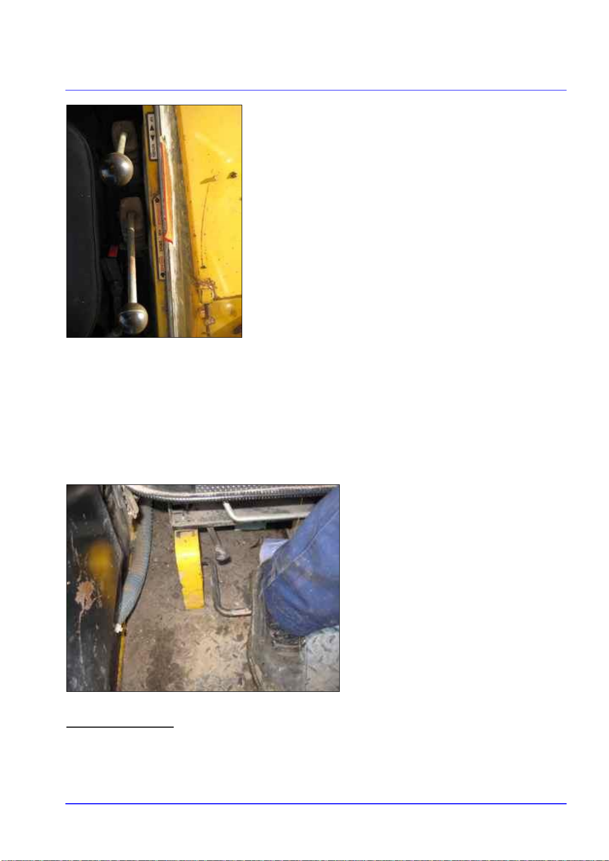
k) When steering any changes of direction must be made slowly with due regard for the
road surface, the type of load and the rear end swing of the Teleporter. The brake
pedals must always be locked together, and only unlocked if they are needed as an
aid to turning in tight places
l) When braking emergency stops are to be avoided, especially in a forward direction –
the vehicle will stop but the load may not. Apply the Parking Brake before leaving the
vehicle and, if on a slope, also chock the wheels.
m) Gradients must be treated with respect. The Teleporter has a relatively narrow track
and if heavily laden may become unstable when driven across a slope. Drive up and
reverse down slopes when laden. Drive down and reverse up slopes when unladen.
Do not attempt to turn on a slope but proceed to the top or the bottom and turn safely
on the level. Always use rear wheel drive on sloping surfaces.
n) The lifting fork blades must be equally spaced from the centre and set at the
maximum width apart that the load or pallet will allow. Additionally the forks must
always be tilted back except when entering or discharging a pallet.

Marconi Sailing Club Ltd. MSCP83
Issue 2
Sanderson Teleporter Instructions & Code of Practice 21/03/2014
Page 4 of 17
o) When moving the boom, forks must be maintained in the transport position while the
vehicle is moving. The transport position being the lowest height that provides
adequate ground clearance and allows the operator a clear view of the rear right side
through the mirror. When at a standstill or parked the boom should be lowered to the
ground. When raising the boom the vehicle should be stationary or only very slowly
moving into position for charging or discharging the load.
p) Always watch the boom height especially when entering buildings or when in the
vicinity of overhead cables.
q) Teleporter drivers must ensure all Teleporter activity & any defects to either the
Teleporter or any attachments are recorded in the Teleporter Operations Log Book
and reported to the tractor co-ordinator for action. A ‘Do Not Use’ label must be
securely attached to the Teleporter steering wheel and if relevant to the attachment
as well. Endorsement of the logbook in the appropriate space will enable drivers to
confirm the defect has been rectified. Labels can be found on the shelf in the
hydraulics pump house.
This list is not exhaustive. To view all safety reminders, refer to the Operators
Handbook stored in the barn container on bookshelf.
3. Teleporter Use and Attachments - a guide to their use.
On each occasion the Teleporter is used the following checks must be carried out.
a) The oil level in the crankcase is correct.
b) There is adequate cooling water in the radiator or header tank - to be checked when the engine
is cold.
c) There is adequate fuel in the tractor.
d) The hydraulic oil level is correct.
Sanderson Teleporter Base Unit –General Information
e) Gear selection will be easier if the engine is at minimum revs. Move the forward/reverse lever
into neutral before changing gear. NEVER change gear while on the move.
f) Use two wheel drive whenever possible.
g) Four-wheel drive should be used when operating in slippery or muddy conditions to improve
traction. It should be disengaged as soon as possible when conditions deem it is not necessary.
Always leave the four wheel drive disengaged when leaving the Teleporter and check it is has
been disengaged before starting. The lever is the rear of the two levers to the right side of the
drivers seat.

Marconi Sailing Club Ltd. MSCP83
Issue 2
Sanderson Teleporter Instructions & Code of Practice 21/03/2014
Page 5 of 17
h) The Teleporter may be used with the cab door secured in the open position after ensuring it is
locked open correctly and seat belt is worn.
i) Wheelspin can be reduced by engaging the Differential Lock. This is achieved by pressing down
the bar situated on the cab floor under the front seat cushion with your heel. It is essential that
the differential lock is only engaged when travelling in a straight line and not engaged above 5
m.p.h. or with one wheel spinning much faster than the other. If necessary stop forward travel,
engage the diff lock then proceed forward again. No attempt should be made to turn with the
diff-lock engaged. Release before reaching the turning point.
Operating Hints
Starting the engine.
a) Check the hydraulic tank oil level under the rear cover. Do not overfill.
FRONT
REAR

Marconi Sailing Club Ltd. MSCP83
Issue 2
Sanderson Teleporter Instructions & Code of Practice 21/03/2014
Page 6 of 17
b) Check the engine oil level by accessing the dipstick underneath the right hand side of the
Teleporter between the wheels. If oil is to be replenished use the correct grade and type of oil
and ensure the correct filler port is used . There are three filler ports under the hood on the Right
side of the Teleporter. The engine oil filler is the one that is rearmost, next to the engine exhaust
manifold and is appropriately marked as such.
c) Ensure that the gear lever is in neutral position and that the direction control lever is in neutral
position.
d) Ensure that the “STOP” knob is fully pushed in.
e) Open throttle halfway
f) In warm weather or when engine is hot, start the engine by turning the key clockwise into first
“ON” position then into second position “STARTER” position to engage the starter motor and
release when engine runs back to position “ON”. Operate the starter motor for a maximum of 10
seconds or until the engine starts.
g) During periods of cold weather turn key one notch anti clockwise and hold for 30 secs to operate
the heater, then turn it a second notch anti clock to start. When engine runs turn key clockwise
to ignition “ON” position.
h) Check that all warning lights extinguish and gauges are reading normal before continuing. If not
stop the engine and assess the problem.
i) Raise the boom sufficiently to gain access to the radiator and stop engine (as described below)
j) Open the side shield and top shield and check the radiator coolant level. Replace the shield,
ensuring that the “anti battery short” rubber mat is in place across the battery terminals to
prevent the possibility of shorting. Start the engine and lower the boom.
Stopping the engine.
k) Apply parking brake firmly and set direction control lever and gear lever in neutral.

Marconi Sailing Club Ltd. MSCP83
Issue 2
Sanderson Teleporter Instructions & Code of Practice 21/03/2014
Page 7 of 17
l) Allow to tick over for a couple of minutes to cool down.
m) Pull red "STOP" knob on right side of dash panel until engine stops. Push it back in again once
engine has stopped.
n) Turn key to “OFF” position AFTER engine has stopped. (turning key off too soon may damage
the alternator)
o) Check to ensure that all LIGHTS ARE OFF, as it is possible to leave them on. Make sure all
windows are closed SHUT before leaving the tractor.
p) At the end of a days work always replenish the fuel tank and ensure that the boom is fully
retracted and the boom is lowered to the ground.
q) Once the engine has stopped release the hydraulic pressure in the cylinders by operating all the
levers
r) Lastly, lock the cab door.
Moving Off and Stopping
a) Release the handbrake and apply the footbrakes.
b) With the engine running at low idle, firstly select the gear on the manual gear lever. (second from
the left) Use the lowest gear you think you will need for the task. Normally on the MSC club site
you will not need to use the 3rd or 4th gear. Usually 1st and 2nd will suffice for working around
boats, buildings and equipment.
c) With the engine at low idle push/pull the forward/reverse lever (first from left) in the direction you
want to travel. Release the footbrake and increase the engine revs to move forward or reverse.
Increasing the engine speed will increase ground speed. A torque converter is fitted to the
Teleporter and therefore there is no clutch pedal as on a car or tractor. To stop direction of travel
decrease engine speed and apply footbrake and/or return the forward/reverse lever to neutral
position.
d) When changing direction of travel always slow down the engine speed to idle, stop, then operate
the forward/reverse lever to change direction of travel.
e) In an emergency apply footbrake at the same time as pulling the forward/reverse lever into the
neutral position.
Boom Control

Marconi Sailing Club Ltd. MSCP83
Issue 2
Sanderson Teleporter Instructions & Code of Practice 21/03/2014
Page 8 of 17
a) Always use your experience to assess each lift to ensure that the task is within the capability of
the skill of the driver and the capability of the machine. If in doubt, ask the Tractor Coordinator’s
advice or do not carry out the task if it is considered to be possibly dangerous.
b) Always lift from as close in as possible with a short a reach as possible. Never extend the reach
of the boom when the prime mover can be driven closer to the load as this will reduce stability.
Reducing the reach will reduce the load on the hydraulics and will increase the weight transfer
onto the rear wheels.
c) Never lift higher than is necessary and always check that there are not any obstructions such as
power cables.
d) Always lower the boom before moving off to improve lateral stability. Never drive the Teleporter
with a load lifted up higher than is necessary to effect the job.
e) Always ensure that when the boom is being moved that the direction control lever is in neutral
and ground travel is stopped, unless you are manoevering slowly to pick up or drop off a load.
Note: that the speed of the boom cylinders is related to the engine speed. If the engine is running
slowly the cylinder being operated will move slowly. The higher the engine speed means the
boom cylinders will move faster.
f) Always ensure that the levers are operated smoothly and progressively. Erratic movement of the
levers can affect the stability of the Teleporter.
g) There are three principal spring-loaded centralising levers for operating the boom. These are
situated to the right side of the driver’s steering wheel. The boom “RAISE” and “LOWER” lever,
(push to lift and pull back to lower). The boom “EXTEND” and “RETRACT” lever, positioned to
the right of the raise/lower lever, (push to extend, pull back to retract). Finally the boom carriage
control lever, positioned to the rear of the raise/lower lever is the “TILT FORWARD” and “TILT
BACK” lever, (push to tilt forward and pull back to tilt back)
FRONT

Marconi Sailing Club Ltd. MSCP83
Issue 2
Sanderson Teleporter Instructions & Code of Practice 21/03/2014
Page 9 of 17
h) Always release the hydraulic control levers once the cylinder has reached its desired position.
Never allow the relief valves to blow unnecessarily as this will heat the oil and may damage the
pump.
i) “Safe Load Indicator” – This electronic safety device is fitted as an aid to operation and loading of
the unit. It is located to the left of the drivers’ side. It consists of two green, two yellow and one red
lights and an audible alarm. Green indicates a safe load, yellow indicates an optimum load and red
with the alarm sounding indicates an overload. When starting the engine the “Safe Load Indicator”
panel will go through a self-check procedure and the alarm will sound briefly if functioning correctly.
It should not be used to achieve the maximum loading possible. A load should never be moved if
the red light and alarm sounds. If the alarm does sound, ALWAYS retract the boom before lowering
a load, as this will decrease the effective weight being lifted. (The Teleporter balance point is the
centre of the front axle, so by retracting the boom the distance from the load to the pivot point will be
reduced) If the boom is raised to maximum height to collect a high load and the alarm sounds,
retract the boom if possible or replace the load in its original position. NEVER try to lower the load
from maximum height if the alarm has sounded as this will increase the effective load and will
render the machine unstable. (as the boom is lowered from maximum height the distance from the
load to the front axle centre will increase, due to the geometry of the jib) NEVER ignore the overload
warning as the unit has become unstable and means that the Teleporter is overloaded. Use the
“Safe Load Indicator” as an indicator to aid operation and safe working practices.
Working examples are shown in Appendix 3.
Attachments.
GENERAL.
a) The carriage is permanently attached to the end of the boom and consists of a face-plate with
notched upper beam.
b) At the bottom of the carriage on each side is a pair of attachment locking pins controlled by a
single lever on the right side.
c) Additionally there are two additional hydraulic connectors for attaching additional equipment
where necessary.
SAFE LOAD INDICATOR

Marconi Sailing Club Ltd. MSCP83
Issue 2
Sanderson Teleporter Instructions & Code of Practice 21/03/2014
Page 10 of 17
FORKS
a) It is necessary to have two persons to remove and replace the forks as they are heavy and
awkward to handle manually.
b) The forks are slid onto the upper carriage beam and are held in place by means of spring-loaded
pins that locate into the notches of the beam.
c) They must always be equally spaced from the centre line of the carriage to ensure equal loading
of the forks and must be as far apart as the load or pallet will allow.
d) The forks must always be tilted back except when entering or discharging the load.
e) The boom must always be as close as possible to the ground when the Teleporter is moving.
Also this enables the driver to use the mirror on the right side to view the rear right side of the
Teleporter.
f) Changes of direction must be made slowly with due consideration to the load being carried and
the proximity of the rear right hand side to any vehicle or obstruction.
g) Drive slowly at all times –never rush at the job.

Marconi Sailing Club Ltd. MSCP83
Issue 2
Sanderson Teleporter Instructions & Code of Practice 21/03/2014
Page 11 of 17
MAN UP CAGE
a) This attachment fits onto the forks. Space Forks centrally on carriage & to the correct width of
channels on man up cage remove locating pin & lock pins & drive into cage locating both
channels fully. Place locating pins in into rear of channels behind fork heels & FIT Lock pins DO
NOT use cage if any part is not fitted correctly or missing.
b) The cage must be secure for operatives, ensure that the chain securing the opening is fitted.
c) The cage floor must be clear & undamaged.
d) The Safe Working Load (SWL) is 500kgs. This is a maximum load that applies to the cage,
carriage and forks.
e) The cage is designed for TWO MEN only. NO LIFTING load is allowed when used as a Man Up
cage
f) When cage is fitted operatives are must not travel in cage when the Teleporter is moving. The
operatives may only enter cage once the Teleporter is at the required site.
g) The cage must only be allowed for maintenance jobs only. (this is a Legal Requirement for
use of man up cage)
h) Any person using the man up cage shall do so wearing the tested, safety harness provided
by the club and be attached to the man up cage at all times.

Marconi Sailing Club Ltd. MSCP83
Issue 2
Sanderson Teleporter Instructions & Code of Practice 21/03/2014
Page 12 of 17
BUCKET
a) The bucket is fitted to the Carriage. Firstly the forks may need to be removed. There is a slot in
the centre of the lower rail of the carriage that allows the lower lip of the fork to be pulled forwards
to release it from the rail. The first fork must be slid over to be adjacent to this slot and the bottom
pulled upwards to release. The carriage will then need to be tilted to release the top lip of the fork
from the carriage rail. It is necessary to have two persons to remove and replace the forks as
they are heavy and awkward to handle manually. Remove the second fork in the same way.
Drive into the centre of bucket and lift the boom so top lip of carriage hooks under top rail of
bucket. When it is hooked in tilt back the carriage until side rails cover the bucket rails. Then lift
lever to locate lock the pins into bucket holes to secure the bucket to the carriage.
b) The safe working load with bucket fitted is 2500kgs. The bucket must be calculated as part of the
load. NEVER OVERLOAD. A full bucket of sand or shingle will most likely overload the
Teleporter. Take care when raising the load. If overloaded the “Safe Load Indicator” will alarm. If
this occurs empty some of the load immediately. Never extend boom with full load.

Marconi Sailing Club Ltd. MSCP83
Issue 2
Sanderson Teleporter Instructions & Code of Practice 21/03/2014
Page 13 of 17
CRANE JIB
a) The crane jib must be used for lifting any object that is not a pallet or flat based load.
b) The crane jib must be slid onto the forks and secured so that its centre line is a maximum of
500 mm to the front of the carriage.
c) Ensure that if a shackle is used to attach either chains or slings to the Crane Jib then it must
be also tested to the match the maximum load of 500 kg. These are located in the metal box
on the side of the Teleporter.
d) Never use chains or slings directly onto the forks to lift any load
e) When moving a load ensure that the load is restrained from swinging freely or damage may
result to the Teleporter or bystander.

Marconi Sailing Club Ltd. MSCP83
Issue 2
Sanderson Teleporter Instructions & Code of Practice 21/03/2014
Page 14 of 17
REMEMBER THAT THE TELEPORTER AND ITS ATTACHMENTS, IF
MISUSED, CAN BE DANGEROUS AND A HAZARD TO OPERATOR AND
BYSTANDERS. IF IN DOUBT STOP AND REVIEW THE OPERATION.
Appendices 1 to 3 follow on Pages 15 to 17
Reviewed on 21st March 2014 by the Health & Safety Sub-committee
To be reviewed after 4 years.Next review due March 2018

Marconi Sailing Club Ltd. MSCP83
Issue 2
Sanderson Teleporter Instructions & Code of Practice 21/03/2014
Page 15 of 17
Appendix 1
APPROVED HAND SIGNALS.

Marconi Sailing Club Ltd. MSCP83
Issue 2
Sanderson Teleporter Instructions & Code of Practice 21/03/2014
Page 16 of 17
Appendix 2
MAXIMUM LOAD CAPACITY

Marconi Sailing Club Ltd. MSCP83
Issue 2
Sanderson Teleporter Instructions & Code of Practice 21/03/2014
Page 17 of 17
Appendix 3
ELECTRONIC SAFE LOAD INDICATOR
Table of contents