S&S Northern MERLIN GDPX+ User manual

Installation & Operation Manual Merlin GDPX+
GDPXPLUS - IOM Iss: 802-21 1
MERLIN GDPX+
Gas Detection Panel
Installation & Operation Manual
Please read this manual carefully and retain for future use.
S&S Northern provide a range of detection panels which can be used in many applications such as factories, car
parks, shopping centres and most commonly for this model - boiler houses.
The GDPX+ can be used with up to 16 Merlin gas detectors (sold separately) for monitoring and detecting gas
including carbon monoxide, liquid petroleum gas and methane.
The information contained within this manual should be referenced for typical installation and operation only.
For specific requirements that may deviate from the information in this guide –contact your supplier.

Installation & Operation Manual Merlin GDPX+
GDPXPLUS - IOM Iss: 802-21 2
Contents
Important Warning Statements.....................................................................3
Installation......................................................................................................4
Planning ......................................................................................................................... 4
Quick Installation Arrangement...................................................................................... 4
Fixing ............................................................................................................................. 5
Board Connections Diagram ......................................................................................... 5
Board Connections Overview ........................................................................................ 6
Wiring your Detector...................................................................................................... 8
Creating a Detector Chain ............................................................................................. 8
Detector Chain ID Switches ........................................................................................... 9
120ohm Termination Resistance ................................................................................... 9
Quick Circuit Test .......................................................................................................... 9
Access Configuration Settings.....................................................................................10
Settings Menu..............................................................................................................10
Settings Options Explained..........................................................................................10
Factory Set Condition .................................................................................................. 11
Connecting to the Internet ........................................................................................... 11
Trouble Shooting .........................................................................................................11
Specification ................................................................................................................ 12
Operation .....................................................................................................13
First Power Up .............................................................................................................13
Main Screen................................................................................................................. 13
Zone Screens............................................................................................................... 13
Diagnostic Screen........................................................................................................ 14
Fire Alarm Bypass........................................................................................................14
Alarm Messages .......................................................................................................... 14
Alarm Message List .....................................................................................................15
General Maintenance ..................................................................................16
Cleaning....................................................................................................................... 16
Manual Circuit Simulation Test ....................................................................................16
Bump Test (Gas Response Check).............................................................................. 16
Service & Calibration ..................................................................................18
Detector Service Message........................................................................................... 18
Enter Service Mode ..................................................................................................... 18
Detector Calibration .....................................................................................................19
Failed Calibration ......................................................................................................... 20
Gas Sensor Types & Reaction Times ..........................................................................21
End of Life (EOL) .........................................................................................................21
Service Record ............................................................................................................ 22
Installation & Operation Manual Merlin GDPX+
GDPXPLUS - IOM Iss: 802-21 3
Important Warning Statements
Please take the time to thoroughly read this user’s guide which should be retained for future reference.
It is recommended that this device be commissioned upon installation and serviced at least annually.
Do not apply lighter gas or other aerosols to detectors –this will cause extreme damage to the gas sensing elements.
High concentrations of alcohol found in many products may damage, deteriorate or affect the gas sensing elements of
the detectors –Avoid exposure near your devices.
This device is designed to detect the gas displayed on screen and in the designated zone area from any source of
combustion or dangerous level. It is NOT designed to detect smoke, fire or other gases and should NOT be used as
such.
This device provides early warning of the presence of gas, usually before a healthy adult would experience
symptoms. This early warning is possible provided your alarm is located, installed and maintained as described in this
guide.
Never ignore your device when in alarm. Actuation of your alarm indicates the presence of an error or significant
issue that requires immediate attention.
This device requires a continual supply of electrical power –it will not work without power.
This device should not be used to substitute proper installation, use and/or maintenance of fuel burning appliances
including appropriate ventilation and exhaust systems.
This device does not prevent dangerous gasses from occurring or accumulating.
This unit may not fully safeguard individuals with specific medical conditions. If in doubt, consult a doctor/physician.
Your product should reach you in perfect condition, if you suspect it is damaged, contact your supplier.
Manufacturer’s Warranty
Warranty coverage: The manufacturer warrants to the original consumer purchaser, that this product will be free of defects in
material and workmanship for a period of three (3) years from date of purchase. The manufacturer’s liability hereunder is limited to
replacement of the product with repaired product at the discretion of the manufacture. This warranty is void if the product has been
damaged by accident, unreasonable use, neglect, tampering or other causes not arising from defects in material or workmanship.
This warranty extends to the original consumer purchaser of the product only.
Warranty disclaimers: Any implied warranties arising out of this sale, including but not limited to the implied warranties of description,
merchantability and intended operational purpose, are limited in duration to the above warranty period. In no event shall the
manufacturer be liable for loss of use of this product or for any indirect, special, incidental or consequential damages, or costs, or
expenses incurred by the consumer or any other user of this product, whether due to a breach of contract, negligence, strict liability
in tort or otherwise. The manufacturer shall have no liability for any personal injury, property damage or any special, incidental,
contingent or consequential damage of any kind resulting from gas leakage, fire or explosion. This warranty does not affect your
statutory rights.
Warranty Performance: During the above warranty period, your product will be replaced with a comparable product if the defective
product is returned together with proof of purchase date. The replacement product will be in warranty for the remainder of the original
warranty period or for six months –whichever is the greatest.
Information on waste disposal for consumers of electrical & electronic equipment.
When this product has reached the end of its life it must be treated as Waste Electrical & Electronics Equipment (WEEE).
Any WEEE marked products must not be mixed with general household waste, but kept separate for the treatment, recovery and
recycling of the materials used. Please contact your supplier or local authority for details of recycling schemes in your area.
At the end of their working life, electrochemical sensors for oxygen and carbon monoxide detectors should be
disposed of in an environmentally safe manner.
Alternatively all detectors can be securely packaged and returned to S&S Northern clearly marked for disposal.
Electrochemical sensors should not be incinerated as this may cause the cell to emit toxic fumes.

Installation & Operation Manual Merlin GDPX+
GDPXPLUS - IOM Iss: 802-21 4
Installation
Planning
The Merlin GDPX+ is a multi-zone gas detection panel which can be used in many applications such as
factories, car parks, shopping malls and most commonly - boiler houses.
It can be used with up to 16 Merlin gas detectors (model TFT) for monitoring and detecting gas including
carbon monoxide, liquid petroleum gas and methane. The GDPX+ also has provisions to identify and
monitor gas levels via an internet connection.
The GDPX+ system can be integrated with, but not limited to, a BMS (building management system)
including Modbus, a fire panel, external alarms and remote emergency shut-off buttons.
Please refer to your detector manual for important information regarding coverage, location and
positioning including areas and conditions to avoid!
Locations for detectors will vary based on the intended application and target gas, they should be located
near identified sources of a potential gas leaks/ pockets where hazardous gas could quickly accumulate
and areas of identified consequential risk.The composition of the target gas and its density relative to air
are used as the basis for any recommended height of sensors.
Generally, the installation height of a sensor for a heavy gas (such as propane) would be close to the
lowest point in the area, and for a light gas (such as methane) would be close to the highest point in the
area. Any recommended heights may vary based on air flow and temperature conditions in addition to the
proposed application and location –this is particularly apparent with oxygen depletion sensors, and the
target gas that they are used for.
Quick Installation Arrangement
The control panel should be located outside of the hazardous area that it is monitoring.
Easy accessibility is required both for status observation and alarm purposes.
Where connections may exceed 100 metres from one control panel –Contact your supplier!
We recommend all Merlin gas detection equipment is commissioned by competent/trained engineers to
ensure correct installation and operation.
The Merlin range of gas detectors are optimum calibrated when manufactured. However, we strongly
recommend the detectors response and fault conditions are tested and validated once installed. This will
ensure the equipment is performing as intended and free from unforeseen damage caused by
transit/installation.
Installation & Operation Manual Merlin GDPX+
GDPXPLUS - IOM Iss: 802-21 5
Fixing
Unpack all the parts!
Designed for surface mounting, it must be installed by a licensed, insured contractor.
1. Carefully remove the front cover from the unit by
unscrewing the four bolts located at each corner. To do
this –use the socket wrench provided.
2. Mark the four screw holes located on the back of the
enclosure to the wall. Ensure the wall surface is flat to
prevent base distortion.
3. After executing the mounting and the connections –
replace the front cover and insert the security caps over
the four bolts.
Board Connections Diagram
Be careful when creating access for cables –Damage to boards will void any warranty!
Any damage attempting to remove the circuit board parts may void any warranty!
Wiring of different circuits shall be separated by means of routing, clamping or barrier!
All Class 2 wiring is to be installed within flexible tubing to maintain segregation between circuits!
For MODBUS communications, a shielded cable is used!

Installation & Operation Manual Merlin GDPX+
GDPXPLUS - IOM Iss: 802-21 6
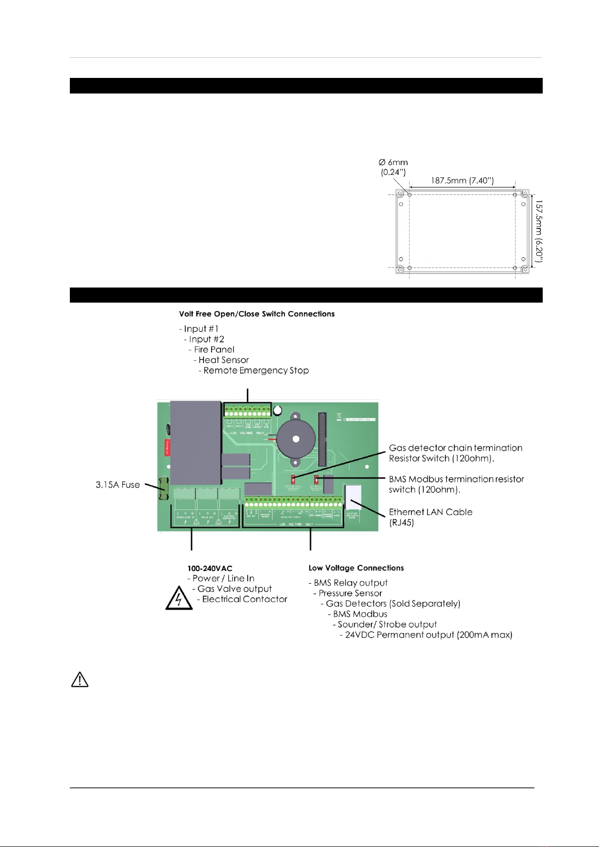
Board Connections Overview
POWER / LINE IN
100-240Vac mains power should be supplied to the [POWER/LINE IN] connector using a 3 core cable and
fused at 3A. On connecting the mains supply to the panel the power LED indicator will light up –this is
located on the front cover.
VALVE OUT
100-240Vac electrical power output from the [VALVE OUT] connector using a 3 core cable
can be connected to a gas solenoid valve which can shut the gas supply on alarm status. A
pressure sensor should be connected to the downstream port.
Refer to your valve manual for more information and wiring!
ELECTRIC CONTACTOR
100-240Vac electrical power output from the [ELECTRIC CONTACTOR] connector using a 3
core cable can be connected to a contactor.
Refer to your contactor manual for more information and wiring!
BMS OUTPUT
Connections are available on the board for Building Management Systems.
These are volt free connections.
This is a relay that changes state in alarm or when the gas is on/off and can be used in conjunction with
the 24V DC output and other external relays that affect other devices and controls such as purge fans and
audible alarms etc.
PRESSURE SENSOR
The pressure sensor is wired to the [PRESSURE SENSOR] connector and screwed
into the downstream port of the gas solenoid valve.
Connect the pressure sensor as shown:
Red [+] Black [-] Blue [IN]
The sensor will monitor the gas supply pressure and if pressure drops below
12mbar–the gas valve will close as this could mean a gas leak is present.
The pressure sensor operating pressure is: 0 –100mbar.
Gas pressure will be ignored if gas proving is OFF!
More information can be found in section: Settings.
DETECTOR CHAIN
12-24Vdc power and modbus RTU communication data is wired to gas detectors. Up to 16 detectors can
be connected, chained in parallel up to approx. 100 metres from the panel depending on chain
configuration, wire type for power and condition.
For more information do to section: Wiring your Detector.

Installation & Operation Manual Merlin GDPX+
GDPXPLUS - IOM Iss: 802-21 7
BMS MODBUS
Connections for Master/Slave protocols used in Building Management Systems to communicate between
devices including the GDPX+ panel are used with [BMS MODBUS] –RTU.
For MODBUS communications, a shielded and twisted cable is used.
Any cable with similar characteristics can be used to connect all the devices together.
The shielding can be of 2 types: braided [mesh of thin conducting wires] or foil (consisting of a thin sheet
of metal covering the twisted wires). If you are encountering noise or irregular problems with a modbus
link, the problem is likely related to grounding, incorrect shielding or wiring mains power next to Modbus
wiring.
Communication issues may occur where the bus length is too long or high baud rates are used.
In this instance –the [BMS Modbus Termination Switch] on the board may help the quality of the data
signal when turned on at the last and/or first device!
SOUNDER-STROBE
There are connections for an external sounder alarm/ strobe lighting to activate on alarm.
24V DC OUTPUT
This is a permanent 24V DC power output for external auxiliary devices. Max output: 200mA
INPUT 1 & INPUT 2
These terminals are connections for selectable external devices which send an ‘open/close’ circuit signal
to the GDP-X panel such as a current monitor, CO2 monitor or extra emergency shut buttons and heat
sensors - selectable in the Settings menu.
FIRE PANEL
The terminal for fire alarms is detailed on the circuit board as [FIRE PANEL].
HEAT SENSOR
The terminal for heat sensors/ thermal links is detailed as [HEAT SENSOR]. Additional Heat Sensors can
be connected to [INPUT 1] or [INPUT 2] terminals.
EM STOP
Connections for remote emergency shut-off or stop buttons is detailed on the circuit board as [EM STOP].
Additional shut-off buttons can be connected to [INPUT 1] or [INPUT 2] terminals.

Installation & Operation Manual Merlin GDPX+
GDPXPLUS - IOM Iss: 802-21 8
Wiring your Detector
12-24VDC power and Modbus communication data cables are wired to Merlin gas detection panels –
GDP2X or GDPX+. Both terminals are identified as [DETECTOR CHAIN + - D+ D-]. Up to 16 detectors can
be connected, chained in parallel up to approx. 100 metres from the panel depending on chain
configuration, wire type for power and condition.
If devices are not grounded, they can give false readings or become a safety hazard!
Where connections may exceed 100 metres from one control panel –Contact your supplier!
Ensure the termination resistance switch is turned on at each end of a chain!
MODBUS Connection
A shielded and twisted 2 or 4 core cable is used to wire the data terminals [D+ & D-).
Any cable with similar characteristics can be used to connect all the devices together.
The shielding can be of 2 types: braided [mesh of thin conducting wires] or foil
(consisting of a thin sheet of metal covering the twisted wires).
One example of such cable is BELDEN 3082A. If you are encountering noise or
irregular problems with a bus link, the problem is likely related to grounding,
incorrect shielding or wiring mains power next to Modbus wiring.
To ground the data cable, the shield should be connected to ‘Power’ [-] terminals!
Creating a Detector Chain
Create a detector chain by connecting detectors in a parallel (daisy chain) method.
Any other way may cause issues or damage to the overall system.
**Single chain example.
**Split chain example

Installation & Operation Manual Merlin GDPX+
GDPXPLUS - IOM Iss: 802-21 9
Reversing the [D+] and [D-] connections of any device can lead to the whole system to stop working
owing to reverse polarity found on the terminals. In order to avoid this problem, it is recommended that
the cable of same colour should be used to connect all [D+] terminals together and similarly cable of same
colour to be used to connect all [D-] terminals together.
**Where connections may exceed 100 metres from one control panel –Contact your supplier!
Detector Chain ID Switches
When wiring multiple detectors in a chain it is important to identify
each and every detector installed for the control panel to receive and
display accurate data corresponding with the correct detector type.
The ID configuration diagram is printed onto detector boards for quick
reference. All detectors are factory set to ID1.
ID Switches must be configured for each and every
detector connected to receive and display accurate data!
We recommend a plan, map and/or marking the detector enclosures detailing ID and location!
120ohm Termination Resistance
Signal communication issues may occur where the bus length is too long, high
baud rates are used or signal reflections are occurring.
To avoid this, terminating at each end of a chain may help the quality of the data
signal by turning on the 120ohm terminal resistor switch.
If a split chain is used, terminate the last detector in each chain.
If a single chain is used, terminate the first device (Panel) and last device (Detector).
Split chain Single chain
Quick Circuit Test
Access to the interior of the control panel or detector, when carrying out any work, must only be
conducted by trained personnel.
This does not test the gas sensing element itself.
When the test button on the circuit board is pressed and held the detector will simulate an
open circuit to ensure configured systems, outputs, alarms, indications and other external
devices operate as intended in response to gas. When the test button is released –the
test sequence will terminate and return to normal operation.

Installation & Operation Manual Merlin GDPX+
GDPXPLUS - IOM Iss: 802-21 10
Access Configuration Settings
On the front fascia circuit board you’ll find a SETTINGS dip-switch –when switched to ON, the screen will
display the settings menu –you can now configure your GDPX+.
To view, change and save settings, you must provide mains power to [POWER/LINE IN].
When changes have been made –turn the SETTINGS switch OFF and the system will automatically
restart.
Settings Menu
The GDPX+ has a touch screen which allows the engineer/ user to configure the system. There are two
menu screens which are selectable by touching either page number (1 or 2).
Adjust the screen brightness. Change/Select option
Press or slide the cursor up and down. Press the blue option box or press and hold.
When changes have been made –
turn the SETTINGS switch OFF
and the system will automatically
restart.
Settings Options Explained
FUNCTION
OPTION
Explanation
BMS relay ON/OFF for-
- Gas
- Error
Gas changes relay state with gas valve status only.
Error changes relay state upon all alarm messages.
Auto Start-
- ON
- OFF
In the event of a power loss - the GDPX+ will restart automatically when
power is restored, or not.
Modbus Address-
- 1-32
GDPX+ panel address form master BMS Modbus.
Modbus Baud Rate-
- 9600
- 19200
- 38400
- 57600
- 115200
Modbus data exchange speed (bit per second).
FAB Auto Reset
- ON
- OFF
Select ON for the GDPX+ to reset with the fire panel automatically following
fire panel alarm.
OFF to reset the GDPX+ manually following alarm.
INPUT 1 name-
- FAN
- NG
- CO
- LPG
- CO2
- EM
- HS
External devices connected to [INPUT 1] terminal i.e. gas detectors,
emergency stops, heat sensors, fans and CO2 monitors.

Installation & Operation Manual Merlin GDPX+
GDPXPLUS - IOM Iss: 802-21 11
INPUT 2 name-
- FAN
- NG
- CO
- LPG
- CO2
- EM
- HS
External devices connected to [INPUT 2] terminal i.e. gas detectors,
emergency stops, heat sensors, fans and CO2 monitors.
FAB timeout-
- 15 min
- 30 min
- 45 min
Time (in minutes) that the Fire Alarm Bypass (FAB) feature will be enabled
upon each activation.
Fill time
- OFF
- 5 sec
- 10 sec
Time (seconds) the gas valve is open to fill the gas line on power up or reset.
Prove time must be selected.
Prove time-
- OFF
- 30 sec
- 50 sec
Time (seconds) the GDPX+ tests the gas line for leaks on power up or reset.
Fill time must be selected.
Factory Set Condition
Screen Brightness-
- 100
INPUT 1 name-
- FAN
BMS relay ON/OFF for-
- Gas
INPUT 2 name-
- FAN
Auto Start-
- OFF
FAB timeout-
- 30 min
Modbus Address-
- 1
Fill time-
- 5 sec
Modbus Baud Rate-
- 19200
Prove time-
- 30 sec
FAB Auto Reset
- OFF
Connecting to the Internet
Simply connect your LAN cable into the LAN cable port on the GDPX+ if fitted.
Trouble Shooting
Fault.
Possible Cause/Correction.
Detector not responding.
oIncorrect wiring.
oID switches not properly configured.
oTermination switches not set up correctly.
Service message
oDetector requires service –contact supplier.
End of Life message
oDetector requires replacement –contact supplier.
No internet connection
oContact internet provider.
oReset GDPX+.
Gas proving not working
oFill time or gas proving not selected in menu. Both must be ON.
oPressure Sensor not connected to downstream port of gas valve.

Installation & Operation Manual Merlin GDPX+
GDPXPLUS - IOM Iss: 802-21 12
Specification
Product:
Gas Detection Panel
Model:
GDPX+
Display
4.3” Touch Screen TFT
Power Input Voltage
100-240V AC
Gas Valve Output Voltage
100-240V AC
Electrical Contactor Output Voltage
100-240V AC
BMS Max Output
3A
BMS Modbus protocol
RTU
Current Consumption
48W max (fully loaded)
Internal Fuse
3.15A
Operating Temperature
0 –50°C (32 –122°F) 30-85%RH Non-Condensing
Audible Alarm Buzzer dB
65 dB (300mm distance in quiet conditions)
Pressure Sensor Operating Pressure
0 - 100mbar
Wire ratings:
18AWG min
Internet connection
Ethernet (RJ45)
Housing Material
Polylac PA-765
Flame Rating
UL 94
Approvals
CE, RoHS
O/All Dimensions (H x W x D) mm
180 x 255 x 77mm
We recommend all Merlin gas detection equipment is commissioned by competent/trained engineers to
ensure correct installation and operation.
The Merlin range of gas detectors are optimum calibrated when manufactured. However, we strongly
recommend the detectors response and fault conditions are tested and validated once installed. This will
ensure the equipment is performing as intended and free from unforeseen damage caused by
transit/installation.
Installation & Operation Manual Merlin GDPX+
GDPXPLUS - IOM Iss: 802-21 13
Operation
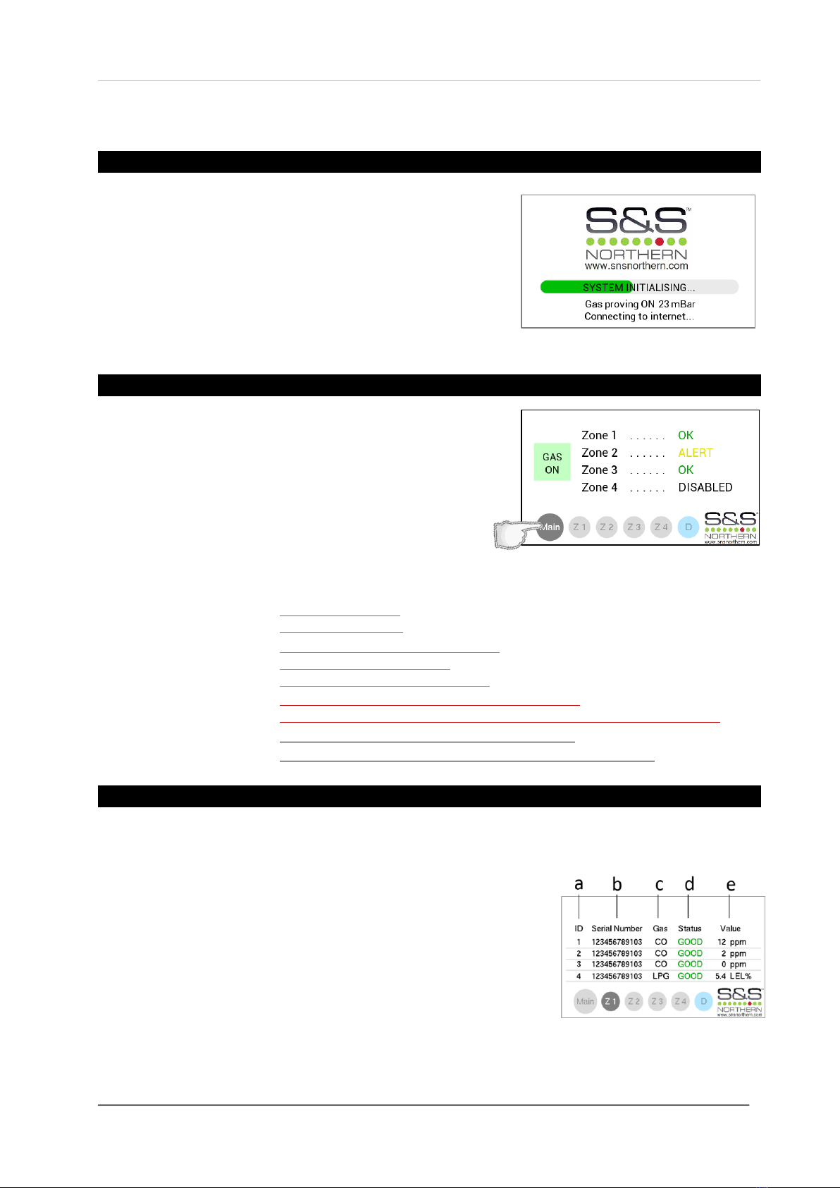
First Power Up
On connecting mains power, the GDPX+ panel will ‘warm up’ for
approximately 60 seconds –during this time the screen will
display an ‘initialisation’ message.
If gas proving is configured in the settings menu –the screen will
display the gas pressure whilst testing the gas line for leaks. The
panel will then search for detectors connected to the GDPX+
panel.
Main Screen
When the GDPX+ has completed initialising and gas proving has
been successful –the Main screen will appear.
The Main screen gives an overview of the status of each zone
being monitored by gas detectors and if the gas supply is
on or off (detectors sold separately).
ZONE STATUS EXPLANATION
OK
oGas levels are safe.
oNo error conditions.
ALERT
oDetector(s) are in Pre-Alarm status.
oDetector(s) require service.
oDetector gas sensor(s) end of life.
ALARM
oDangerous gas levels detected. (Gas is shut off).
oDetector gas sensor fault or detector(s) disconnected. (Gas is shut off).
DISABLED
oNo detector signals are received from the zone.
-- X --
oDetector signal lost, not installed or not configured correctly.
Zone Screens
Switch between zone screens by touching the relevant zone screen, i.e. Z1, Z2, Z3 and Z4.
Each zone can display up to 4 detectors as follows:
a. ID: The detector identification number.
b. Serial Number: The unique serial number for that detector.
c. Gas: The target gas that the detector is monitoring.
d. Status: The status of gas levels, errors and messages.
e. Value: The concentration value of gas being monitored.

Installation & Operation Manual Merlin GDPX+
GDPXPLUS - IOM Iss: 802-21 14
Diagnostic Screen
Touching the Diagnostic screen (D) will display three characteristics of the GDPX+.
a. Gas supply pressure monitored by the pressure sensor
connected to the downstream port of the gas valve.
b. Fire Alarm Bypass (FAB)
(Enable/disable).
c. Internet connection status.
(Connected/disconnected)
Fire Alarm Bypass
The fire alarm bypass (FAB) feature can be enabled at times where fire alarm tests are required.
To enable the FAB feature select the Diagnostic screen and press the OFF/ON button shown where you
are prompted to confirm the action prior to activation.
The FAB feature will be shown on screen when enabled and timeout at the end of the pre-selected time of
15, 30 or 45 minutes (see settings). You can manually disable the FAB by pressing the blue option box to
OFF on the diagnostic screen.
Alarm Messages
The GDPX+ will display messages when in alarm –the messages are prompted from external devices that
have been connected i.e. heat or pressure sensor.
When the GDPX+ goes in to alarm, the user can silence the audible buzzer by pressing MUTE.
During the alarm, the gas will be shut off and no gas detection details will be available.
After the cause of alarm has been rectified –press the RESET button on the GDPX+ panel.
The cause of alarm will have to be investigated and rectified before resetting the GDPX+!

Installation & Operation Manual Merlin GDPX+
GDPXPLUS - IOM Iss: 802-21 15
Alarm Message List
EMERGENCY SHUT OFF
An emergency shut-off button has been activated.
Pressing MUTE on the GDPX+ will silence the audible alarm buzzer.
FIRE PANEL ALARM
The fire alarm panel has reached alarm status.
Pressing MUTE on the GDPX+ will silence the audible alarm buzzer.
HEAT SENSOR ALARM
Heat sensor/ thermal link has reached alarm status.
Pressing MUTE on the GDPX+ will silence the audible alarm buzzer.
LOW PRESSURE (10 second alarm delay)
Pressure sensor has detected a gas leak or a drop in gas pressure
(<12mbar). Pressing MUTE on the GDPX+ will silence the audible alarm
buzzer. Investigate and rectify the issue before RESETTING the panel.
PROVING TEST FAIL
Gas proving has failed test at start up.
Pressing MUTE on the GDPX+ will silence the audible alarm buzzer.
Investigate and rectify the issue before RESETTING the panel.
INPUT 1 & INPUT 2
Alarm messages from terminals [INPUT 1] and [INPUT 2] will depend on the name selected in the settings
menu.
For example, if LPG, NG, CO or CO2 is the selected name for either INPUT terminal you will see the
relevant alarm message. All alarm messages will shut off gas supply.
Or, if FAN is the selected name for either INPUT terminal you will see;
Where FAN is selected, the alarm will have a 10 second delay.
Pressing MUTE on the GDPX+ will silence the audible alarm buzzer.
Investigate and rectify the issue before pressing RESET on the panel.
Installation & Operation Manual Merlin GDPX+
GDPXPLUS - IOM Iss: 802-21 16
General Maintenance
Cleaning
High concentrations of alcohol found in many products may damage, deteriorate or affect the gas
sensing elements –such as; wine; deodorants; stain removers; thinners!
Other gases and substances to avoid; Corrosives (i.e. chlorine & hydrogen chloride); Alkali metals;
Basic or acidic compounds; Silicones; Tetraethyl lead; Halogens and halogenated compounds!
Keep your gas detector in good working order - follow these basic principles;
Remove any dust/debris from the outer enclosure regularly using a slightly damp cloth.
Never use detergents or solvents to clean your device.
Never spray air fresheners, hair spray, paint or other aerosols near the device.
Never paint the device. Paint will seal vents and interfere with the device.
Manual Circuit Simulation Test
Access to the interior of the control panel or detector, when carrying out any work, must only be
conducted by trained personnel.
This does not test the gas sensing element itself.
When the test button on the circuit board is pressed and held the detector will simulate an
open circuit to ensure configured systems, outputs, alarms, indications and other external
devices operate as intended in response to gas.
When the test button is released –the test sequence will terminate and return to normal
operation.
Bump Test (Gas Response Check)
What is a Gas Response Check?
Response checks are often referred to as a ‘BUMP TEST’. Bump tests are important to make sure a
device is able to detect a release of gas as early as possible.
The aim of the bump test is to make sure a gas detector is working at its optimum by briefly exposing the
unit to a known concentration of the target gas that exceeds the highest alarm point. If the detector goes
into alarm and all system outputs/relays activate, then it is working safely.
If the system fails to operate as intended in an alarm state, the gas detector must not be used until a full
inspection and service has been conducted.
Why is it important?
A detector may visually appear in good working order, but its sensitivity can be inhibited by external
factors. Dust, humidity, temperature fluctuations, cleaning products, contaminants or sensor drift (ageing)
can cause a decline in sensitivity and eventual failure.
Regular bump tests are important to make sure the detector is able to detect a release of gas as early as
possible.
Installation & Operation Manual Merlin GDPX+
GDPXPLUS - IOM Iss: 802-21 17
How often should I Bump Test a detector?
Regular bump tests are important to make sure the detector is able to detect a release of gas as early as
possible. A bump test usually takes seconds (gas type dependant) and is often completed alongside a
scheduled fire alarm test, however the frequency should be determined following a risk assessment by
the end user. Remember, bump testing does not remove the need to have gas detectors inspected,
calibrated and serviced periodically by a trained personnel.
What equipment do I need to perform a Bump Test?
Contact your S&S Northern representative for details of suitable bump testing kits and gases.
Kits usually consist of a certified gas cylinder; flow control regulator, tube pipe and applicator cone.
A bump testing gas is usually a concentration mix that exceeds the highest alarm set-point. See below for
recommended gas concentrations for bump testing your detector.
Detector
Bump Test Gas
CO - Carbon Monoxide
400 - 500ppm balance in air.
NG - Methane
0.6 - 0.8% BV (balance in air)
LPG - Liquid Petroleum Gas
0.3 –0.4% BV (balance in air)
H - Hydrogen
5000 - 6000ppm (balance in air)
O2- Oxygen
15% (balance in Nitrogen).
All certified test gases supplied by S&S Northern are classified as non-flammable and non-toxic,
however, they do contain gas under pressure and may explode if heated to extreme temperatures
and cause asphyxiation in high concentrations.
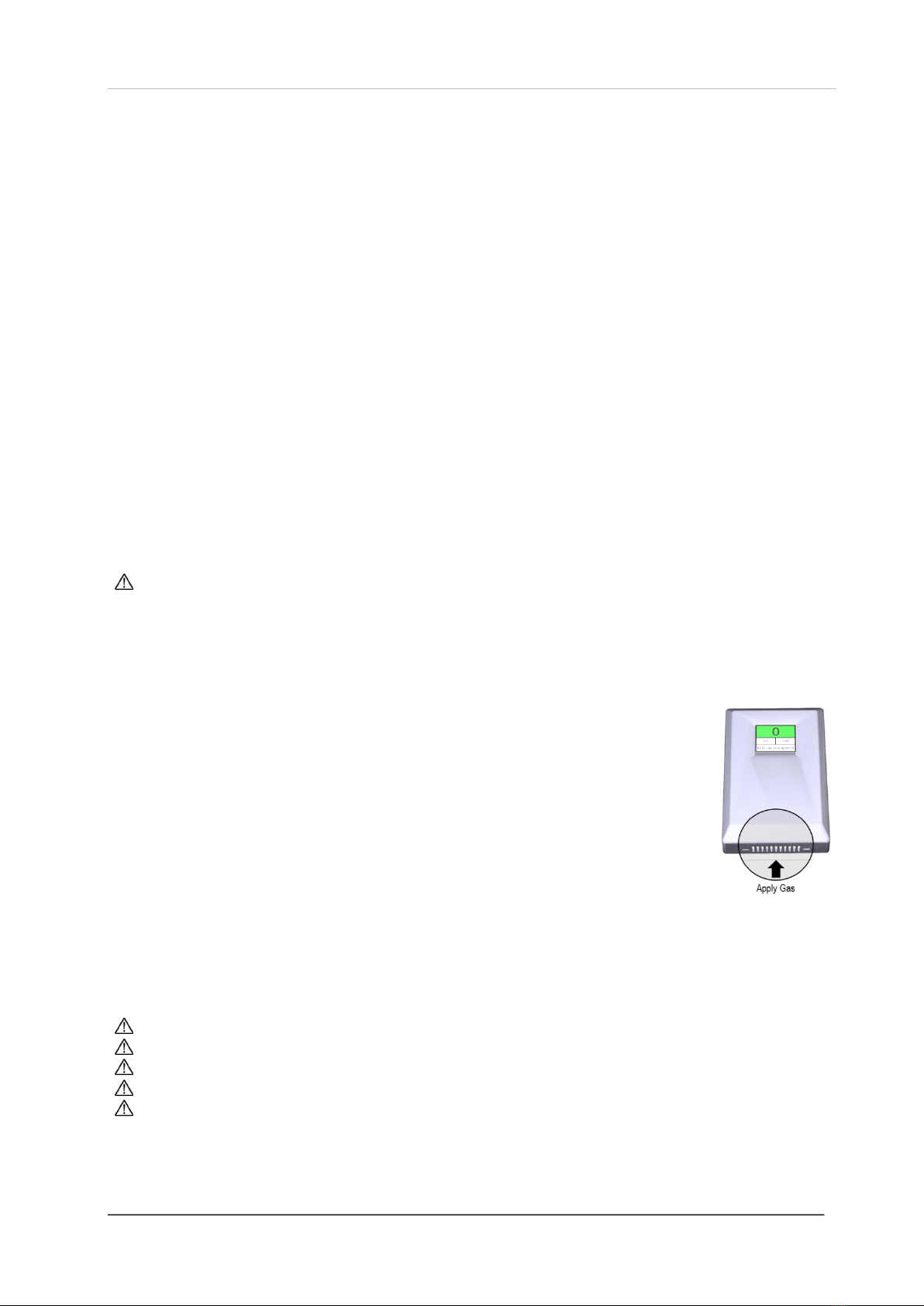
How do I conduct a Bump Test?
1. Ensure you have the correct gas for the device type prior to application.
2. Screw and seal the regulator/valve into the gas cylinder outlet.
3. Once sealed, the regulator pressure gauge will indicate cylinder pressure.
4. Offer up the applicator hose/cone to lower vents.
5. Open the valve/regulator to allow the gas to be delivered at a pre-set flow rate.
7. Wait for the device to enter alarm status and energise configured outputs/relays.
At this point…
9. Remove applicator hose/ cone and turn the gas cylinder regulator/valve off.
10.Wait for the device to return to normal.
11.Reset the system.
Record your test details. (There is a provision for this in your control panel manual).
To increase reaction time, cover the escape vents at the top of the device. Alternatively, enclose the
device and apply gas i.e. in an air tight bag or container.
Always remove the regulator/valve from cylinder after use.
Always check cylinder pressure upon sealing valve –there may not be a sufficient amount of gas.
All cylinders will re-seal upon removal of the regulator/valve.
Always give at least five (5) minutes between testing the same unit or until gas has fully dispersed.
Always consider safety and use equipment in accordance with Safety Data Sheets.
For more help and advice on bump testing –contact us.
Installation & Operation Manual Merlin GDPX+
GDPXPLUS - IOM Iss: 802-21 18
Service & Calibration
Access to the interior of the detector or control panel, when carrying out any work, must only be
conducted by trained personnel.
Before carrying out any work ensure local regulations and site procedures are followed.
Do not tamper with or in any way disassemble the detector.
Do not expose gas sensors to concentrations of alcohol found in many products, these may damage,
deteriorate or affect the gas sensing element –such as; wine; deodorants; stain removers; thinners.
Always remove the regulator/valve from cylinder after use.
Always check cylinder pressure upon sealing valve –there may not be a sufficient amount of gas.
All cylinders will re-seal upon removal of the regulator/valve.
Always give at least five (5) minutes between testing the same unit or until gas has fully dispersed.
Always consider safety and use equipment in accordance with Safety Data Sheets.
Detector Service Message
A service screen will intermittently flash every 30 seconds after one year of operation.
The detector will still operate as intended during this time. This message prompts a recommended
service and calibration of the gas sensor to ensure operational accuracy.
When Merlin gas detector(s) display the service message –the GDPX+ panel will show [SERVICE] on the
status screen. The GDPX+ will still operate as intended and if any dangerous gas levels are detected, your
GDPX+ will show the detector ID in alarm in the top left hand corner.
It is recommended that detectors are inspected and serviced at least annually from the date of installation
for optimum performance and protection.
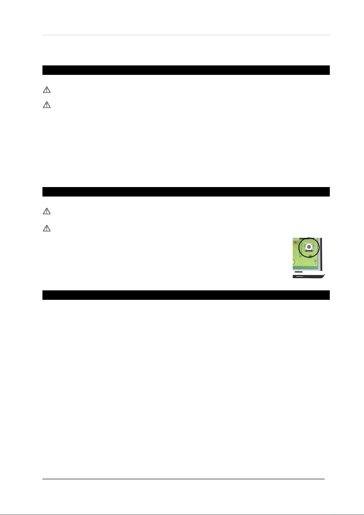
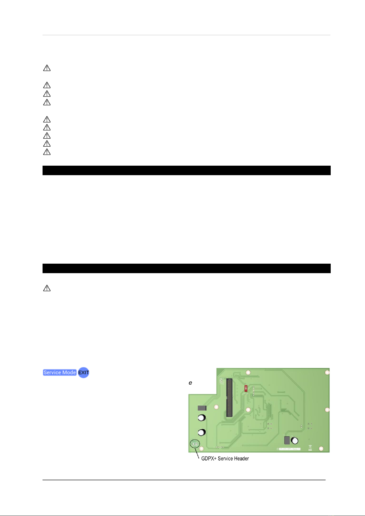
Enter Service Mode
When service mode is activated, the control panel will ignore all detector alarm states and the gas
valve will remain active. The panel will return to a normal operational state after one hour of service
activation unless deactivated manually by pressing the [EXIT] button on screen.
1. Short out the unmarked service header on the control panel circuit board.
2. The screen will display [Service Mode] in the top right hand corner of the digital screen.
3. Proceed to service & re-calibrate detectors.
4. Upon completion of service and calibration –exit Service Mode and press Reset.
Service Mode will be activated for one (1) hour. If more
time is necessary - exit service mode and short
out the service header again. To exit service mode
–press the blue [EXIT] button on screen.
Installation & Operation Manual Merlin GDPX+
GDPXPLUS - IOM Iss: 802-21 19
Detector Calibration
Do not conduct calibration of sensors in conditions outside any recommended ranges.
Use the specified calibration gas only and a fixed flow regulator.
Always use equipment in accordance with their safety datasheets.
Calibration gases must be prepared and mixed to traceable international standards.
Ensure you have the correct gas for the device type prior to application.
Screw the regulator/valve into the gas cylinder outlet.
Once sealed, the regulator pressure gauge (if available) will indicate cylinder pressure.
Always remove the regulator/valve after use.
All cylinders will re-seal upon removal of the regulator/valve.
If a gas sensor is exposed to a concentration significantly above the measuring range it should be
recalibrated as soon as possible afterwards.
To recalibrate a detector, the following procedures and gases MUST be used.
Why recalibrate a detector?
Detectors are pre-calibrated at the time of manufacture, therefore a re-calibration is only required
periodically (annually) to compensate for its sensitivity and accuracy that can be inhibited by external
factors. Dust, humidity, temperature fluctuations, cleaning products, contaminants or sensor drift (ageing)
can cause a decline in sensitivity, accuracy and eventual failure.
Regular gas sensor recalibration is important to prolong the operational life and make sure the detector is
able to detect a concentration of gas as accurately and early as possible. Typical accuracy of gas
measurement is within 10% of the detected concentration.
How often shall I recalibrate a detector?
Calibration should coincide with the annual service message that appears on the detector after each year
of service/operation. Depending on the application and environmental factors, a recalibration can be
conducted at a higher frequency determined by the end user but must be executed by trained personnel.
What equipment do I need to perform recalibration?
Contact your S&S Northern representative for details of suitable calibration kits and gases.
Kits usually consist of a certified gas cylinder; flow control regulator, tube pipe and applicator cone.
To recalibrate a detector, the following gases and concentrations MUST be used.
Detector Type
Calibration Gas
Recommended
gas flow rate
CO - Carbon Monoxide
120ppm balance in air.
Typically 0.3 L/Min
@ 70bar
NG - Methane
0.5% BV (balance in air) 10% LEL
LPG - Liquid Petroleum Gas
0.2% BV (balance in air) 10% LEL
H- Hydrogen
4000ppm (balance in air) 10% LEL
O2- Oxygen
If no residual gas is present then the background air can be used to
perform calibration.
All certified test gases supplied by S&S Northern are classified as non-flammable and non-toxic,
however, they do contain gas under pressure and may explode if heated to extreme temperatures
and cause asphyxiation in high concentrations.

Installation & Operation Manual Merlin GDPX+
GDPXPLUS - IOM Iss: 802-21 20
How do I Calibrate a Detector
Access to the interior of the detector or control panel, when carrying out any work, must only be
conducted by trained personnel.
Before carrying out any work ensure local regulations and site procedures are followed.
Do not tamper with or in any way disassemble the detector.
Do not expose gas sensors to concentrations of alcohol found in many products, these may damage,
deteriorate or affect the gas sensing element –such as; wine; deodorants; stain removers; thinners.
1. Ensure Service mode has been activated on the control panel.
2. Carefully remove the back cover to access the circuit board and gas sensor.
3. Reset Detector by shorting out the 1st and 3rd ICSP pins.
4. Calibrate
a) Short out the [Cal1] header to enter calibration mode during the initial warm up period.
b) Offer up the applicator hose/cone to the gas sensor.
c) Open the valve/regulator to allow the gas to be delivered at a pre-set flow rate.
d) The screen will display a ‘SUCCESSFUL’ text when the calibration is complete.
e) Remove applicator hose/cone and turn the gas cylinder regulator/valve off.
f) On the control panel –exit Service Mode and press Reset.
At this point, when the system and detector returns to a normal operating state!
5. Reset Service Message annual reminder by shorting out the unmarked header.
6. Carefully replace the back cover.
Failed Calibration
Do not reset the service message should the calibration process fail.
If recalibration is unsuccessful a screen text ‘Failed’ will appear. Continue calibration procedure to
reinstate system, the detector will return to normal as it was pre-service and calibration.
Check that the correct gas and concentration has been applied and contact us immediately.
Table of contents
Other S&S Northern Gas Detector manuals

S&S Northern
S&S Northern MERLIN CO DETECTOR X Owner's manual

S&S Northern
S&S Northern Merlin Detector i-S Owner's manual

S&S Northern
S&S Northern Merlin GDP4 User manual

S&S Northern
S&S Northern Merlin 1000BH User manual

S&S Northern
S&S Northern Merlin GDP4 Owner's manual

S&S Northern
S&S Northern Merlin GDP4 User manual

S&S Northern
S&S Northern Merlin GDP2 User manual

S&S Northern
S&S Northern Merlin 1500ppm User manual

S&S Northern
S&S Northern Merlin User manual

S&S Northern
S&S Northern Merlin Series User manual


