S&S Northern Merlin 1000BH Owner's manual

Installation & Operation Manual Merlin 1000BH
Rev: 09 03-21 1
MERLIN 1000BH
Gas Proving & Gas Detection System
Installation, Operation & Maintenance
Please read this manual carefully and retain for future use.
The information contained within this manual should be referenced for typical installation and operation only.
For specific requirements that may deviate from the information in this guide –contact your supplier.

Installation & Operation Manual Merlin 1000BH
Rev: 09 03-21 2
Contents
Important Warning Statements ...................................................................................2
General Information ..................................................................................................... 3
Access & Mounting...................................................................................................................................3
Internal Board Overview ..........................................................................................................................4
Board Connections Overview..................................................................................................................4
Auto Reset Switch.....................................................................................................................................5
BMS Switch ...............................................................................................................................................5
Fill & Prove Time Switch ..........................................................................................................................5
General Specification ...............................................................................................................................5
Operation ...................................................................................................................... 6
Initial Power-Up (Commissioning)...........................................................................................................6
Emergency Shut Off .................................................................................................................................6
LED Indication ...........................................................................................................................................6
General Maintenance ................................................................................................... 7
Cleaning .....................................................................................................................................................7
Bump Test (Gas Response Check) ........................................................................................................7
Important Warning Statements
Please take the time to thoroughly read these instructions which should be retained for future reference.
Detectors are shipped pre-calibrated and configured.
The expected lifetime of a gas sensor is 3-10 years upon initial power up dependant on your target gas and environmental
factors. The device will display a message to indicate this time and should immediately be replaced.
It is recommended that this device be commissioned upon installation and serviced annually by a competent person.
Do not apply lighter gas or other aerosols to the device –this will cause extreme damage to the sensors.
High concentrations of alcohol found in many products may damage, deteriorate or affect the gas sensing elements.
This device is designed to detect the gas type displayed on the screen only.
It is not designed to detect smoke, fire or other gases and should not be used as such.
This device provides early warning of the presence of gas, usually before a healthy adult would experience symptoms.
This warning is possible provided your alarm is installed and maintained in accordance with this manual.
Never ignore your device when in alarm.
This device requires a continual supply of electrical power –it will not work without power.
This device should not be used to substitute proper installation, use and/or maintenance of fuel burning appliances
including appropriate ventilation and exhaust systems.
Multiple detectors may be required to adequately protect property and persons.
This device does not prevent dangerous gasses from occurring or accumulating.
Actuation of your alarm indicates the presence of dangerous levels of gas.
The device is not intended for use in potentially explosive atmospheres.
Seek fresh air supply and contact your local gas emergency service should you suspect a gas leak.
This unit may not fully safeguard individuals with specific medical conditions. If in doubt, consult a doctor/physician.
Your product should reach you in perfect condition, if you suspect it is damaged, contact your supplier.

Installation & Operation Manual Merlin 1000BH
Rev: 09 03-21 3
Manufacturer’s Warranty
Warranty coverage: The manufacturer warrants to the original consumer purchaser, that this product will be free of defects in
material and workmanship for a period of three (3) years from date of purchase or one (1) years for oxygen detectors.
The manufacturer’s liability hereunder is limited to replacement of the product with repaired product at the discretion of the
manufacturer. This warranty is void if the product has been damaged by accident, unreasonable use, neglect, tampering or other
causes not arising from defects in material or workmanship. This warranty extends to the original consumer purchaser of the
product only. Warranty disclaimers: Any implied warranties arising out of this sale, including but not limited to the implied
warranties of description, merchantability and intended operational purpose, are limited in duration to the above warranty period.
In no event shall the manufacturer be liable for loss of use of this product or for any indirect, special, incidental or consequential
damages, or costs, or expenses incurred by the consumer or any other user of this product, whether due to a breach of contract,
negligence, strict liability in tort or otherwise. The manufacturer shall have no liability for any personal injury, property damage or
any special, incidental, contingent or consequential damage of any kind resulting from gas leakage, fire or explosion. This warranty
does not affect your statutory rights. Warranty Performance: During the above warranty period, your product will be replaced with
a comparable product if the defective product is returned together with proof of purchase date. The replacement product will be in
warranty for the remainder of the original warranty period or for six months –whichever is the greatest.
Information on waste disposal for consumers of electrical & electronic equipment.
When this product has reached the end of its life it must be treated as Waste Electrical & Electronics Equipment (WEEE).
Any WEEE marked products must not be mixed with general household waste, but kept separate for the treatment, recovery
and recycling of the materials used. Please contact your supplier or local authority for details of recycling schemes in your
area.
At the end of their working life, electrochemical sensors for oxygen and carbon monoxide detectors should be disposed of in an
environmentally safe manner. Alternatively they can be securely packaged and returned to S&S Northern clearly marked for
disposal. Electrochemical sensors should not be incinerated as this may cause the cell to emit toxic fumes.
General Information
The Merlin 1000BH is a gas pressure proving & gas detection panel for use in various applications.
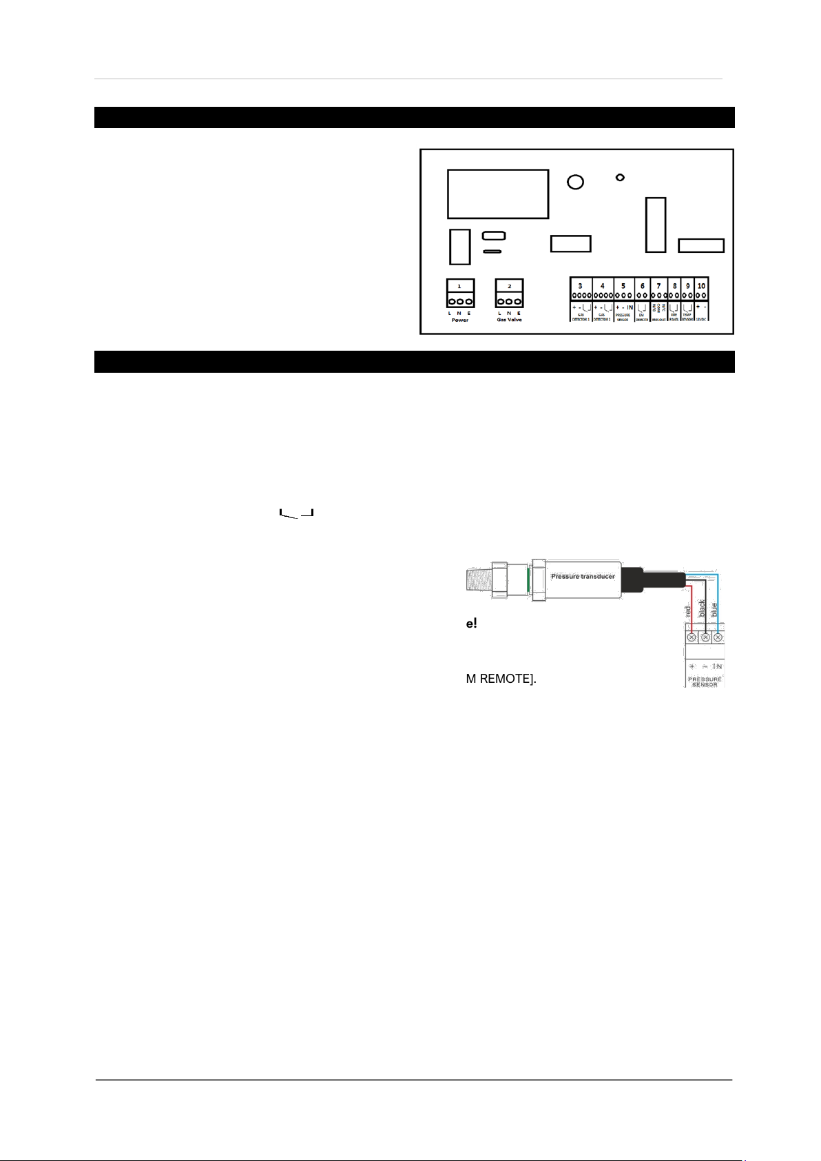
The system comprises a control panel and a gas pressure sensor. The Merlin 1000BH can receive connections from
remote emergency shut-off buttons, two gas detectors, fire panel and heat detector. It also integrates with a BMS.
Access & Mounting
Unpack all the parts!
Designed for surface mounting and must be installed by a licensed, insured contractor or competent person.
Carefully remove the front cover from the unit by unscrewing the four bolts
located at each corner. To do this –use the socket wrench provided. Mark
the four screw holes located on the back of the enclosure to the wall and
ensure the wall surface is flat to prevent base distortion.
After executing the mounting and the connections –replace the front cover
and insert the security caps over the four bolts.
Access to the interior of the panel, when carrying out any work, must be conducted by a competent person.
Before carrying out any work ensure local regulations and site procedures are followed.
We recommend all Merlin gas detection equipment and systems are commissioned by a competent/trained
engineer to ensure correct installation and operation. Contact S&S Northern for more information.

Installation & Operation Manual Merlin 1000BH
Rev: 09 03-21 4
Internal Board Overview
1. POWER: Mains supply 100-240VAC. 3A
2. GAS VALVE: Gas Solenoid Valve Output, 230VAC, 3A.
3. GAS DETECTOR 1: 12vdc power supply.
4. GAS DETECTOR 2: 12vdc power supply.
5. PRESSURE SENSOR Extra Low Volt Input
6. EM REMOTE: Remote Emergency Buttons or Fire Alarm
7. BMS OUT: Normally Closed, Common and Normally Open.
8. FIRE PANEL: Input
9. TEMP SENSOR: Temperature Sensor/Heat Link
10. 12VDC: Permanent output when mains power supplied.
Board Connections Overview
POWER 100-240vac mains power supplied to the [POWER] connector using a 3-core cable fused at 3A.
On connecting the mains supply to the panel the power LED indicator will light up –this is located on the front.
GAS VALVE 100-240vac electrical power output from the [VALVE OUT] terminal using a 3-core cable to a gas
solenoid valve, which can shut the gas supply on alarm status.
GAS DETECTOR 1 & 2
The terminals detailed on the circuit board as [GAS DETECTOR 1] and [GAS DETECTOR 2].
These connections are [+ -] and [ ] these can be wired to a Merlin gas detector. Please refer to the detector
manual for more information. If no detector is used, leave the link in for a closed circuit.
Other detector types are available.
PRESSURE SENSOR
The terminals marked [+ - IN].
+Red Wire / -Black Wire / IN Blue Wire
Screw sensor into the downstream port of the gas solenoid valve!
Operating Pressure = 0- 100mbar
EM REMOTE
The terminal for remote emergency shut-off buttons is marked as [EM REMOTE].
These connections linked out as a factory setting. Remote emergency shut-off buttons should be volt free.
BMS OUT
Terminals are available on the circuit board for connections to Building Management systems.
This relay changes state in alarm or when gas is on/off and can be used in conjunction with the [12VDC] output and
other external relays that affect other devices and controls such as purge fans, audible alarms etc.
Marked on the circuit board as [BMS OUT] Normally Closed (N/C), Common (COM) Normally Open (N/O).
These are volt free connections.
FIRE PANEL
The terminal for fire alarms is detailed on the circuit board as [FIRE PANEL]. These connections are linked out as a
factory setting. Fire alarms should be volt free and wired to the Merlin 1000BH using two-core cable.
TEMP SENSOR
The terminal for heat detectors is detailed on the circuit board as [TEMP SENSOR].
These connections are linked out as a factory setting. Heat detectors should be volt free and wired to the Merlin
1000BH using two-core cable.
12VDC
This is a permanent 12v DC output when there is power at the panel.
Normally used to power a PM2 current monitor. (Supplied separately)

Installation & Operation Manual Merlin 1000BH
Rev: 09 03-21 5
Auto Reset Switch
The panel has a built-in auto reset feature. There is a dipswitch located on the circuit board labelled [AUTO RESET].
This is factory set in the ‘Off’ position i.e. when power is restored after a power cut or loss, the panel has to be
restarted manually. When enabled, the system will restart automatically when power is restored and can be reset
following a fire alarm and when the alarm is cleared.
AUTO SWITCH
CONDITION
OFF
Panel has to be restarted manually following a power cut/loss and/or alarm.
ON
Panel will automatically restart when power is restored and can be reset remotely via a fire panel.
BMS Switch
The panel can be integrated with a BMS to make or break a circuit on gas on/gas off, (valve open or valve closed).
This will tell the BMS whether or not electrical power is being sent to the solenoid. There is a dipswitch located on
the circuit board labelled [BMS SEL]. This is factory set to ‘OFF’ position which signals the BMS on gas on/gas off.
When switched to ‘ON’, the system will only signal the BMS on a fault, i.e. gas detected, EM Stop pressed, etc.
BMS SWITCH
BMS SIGNAL
OFF
Gas on or off only.
ON
Error condition i.e. gas detected, emergency stop pressed.
Fill & Prove Time Switch
There are two switches located on the circuit board labelled [FILL TIME] and [PROVE TIME].
FILL TIME: Amount of time the gas valve opens to fill the gas line on power up or reset.
PROVE TIME: Amount of time the system tests the gas line for leaks on power up or reset.
FILL TIME
PROVE TIME
OFF
5 Seconds (Default)
OFF
30 Seconds (Default)
ON
10 Seconds
ON
50 Seconds
Once the settings are changed - remove power for 10 seconds.
General Specification
Model:
1000BH
Visual Indication
LED
Mains Electrical Power Input
100-240vac
Gas Solenoid Valve Output
100-240vac
Current Consumption
12W max (50mA) @ 120VAC
Internal Fuse
3.15A
Operating Temperature
-10 ~ 40°C 30-80% RH
Audible Alarm Buzzer dB
65 dB (300mm distance in quiet conditions)
Pressure Sensor Operating Pressure
0 -100mbar
Housing Material
Polylac PA-765
Compliance
CE / UKCA
O/All Dimensions (H x W x D) mm / inch
180 x 255 x 77 mm/ 7.08 x 10.03 x 3”

Installation & Operation Manual Merlin 1000BH
Rev: 09 03-21 6
Operation
Initial Power-Up (Commissioning)
When the system is connected to the mains power supply, the Power LED will illuminate RED. Turn the key switch
on to start the system. The system will close the solenoid valve when an emergency stop is pressed, gas detected
or any alarm/fault signal is triggered.
We recommend all gas detection systems be commissioned by a competent/trained engineer to ensure
correct installation and operation!
Emergency Shut Off
The Emergency shut off button is located on the front of the panel. There is also a facility for remote shut off buttons
to be installed (wired in series). The Emergency shut off button(s) will cut off the gas supply when activated.
To reinstate the system, the Emergency shut off button(s) will need resetting and the panel restarted.
LED Indication
Gas on
When the key switch is turned on, the Merlin 1000BH will check the installation for gas leaks. If gas proving is
successful, the gas valve will open and the green ‘Gas On’ LED will illuminate. ON = Gas On / OFF = Gas Off
Testing
This LED will illuminate GREEN for approximately 30 seconds when the panel is checking the integrity of the gas
installation upon start up. GREEN = proving the gas line, do NOT operate any appliances.
Test Fail
Under normal working conditions this LED is off. When the panel detects a gas leak on start-up, the LED will
illuminate AMBER. Gas valve will remain closed. OFF = OK / ON = gas proving failed.
Pressure Low
Under normal working conditions the LED is off. The LED will illuminate AMBER when pressure of the gas supply
drops below 12mBar for 10 secs. The gas valve will close. OFF = OK / ON = gas supply pressure low.
Gas Detector 1 or Gas Detector 2
Under normal working condition this LED is off. If the external Merlin detector connected detects gas this will show
RED and the Gas valve will turn off. OFF = OK / ON = Gas detected.
Heat Detector
Under normal working condition this LED is off. If the temperature of the boilers reaches 72 Degrees Celsius or
higher (Heat detector required), the LED will show AMBER and the Gas valve will turn off. OFF = OK / ON = High
temperature detected (72°C or higher)
EM Stop
If an emergency shut off button (either remote or on the panel) is pressed, the LED will illuminate AMBER and the
gas will be turned off. The EM Stop button must be re-set before restarting the system. OFF = OK / ON = EM Stop
button pressed.
Fire Alarm Panel
If a fire alarm panel is triggered, the LED will illuminate Amber and the gas will be turned off. The Fire alarm panel
must be re-set before restarting the system. Off = OK / ON = Fire alarm panel triggered.

Installation & Operation Manual Merlin 1000BH
Rev: 09 03-21 7
General Maintenance
Cleaning
Keep your system in good working order - follow these basic principles;
Remove any dust/debris from the outer enclosures regularly using a slightly damp cloth.
Never use detergents or solvents to clean your gs detection devices.
Never spray air fresheners, hair spray, paint or other aerosols near the devices.
Never paint devices. Paint will seal vents and interfere with the safety equipment.
Concentrations of alcohol found in many products may damage, deteriorate or affect the gas sensing
elements such as; wine; deodorants; stain removers and thinners. Other gases and substances to avoid are;
corrosives (i.e. chlorine & hydrogen chloride); alkali metals; basic or acidic compounds; silicones; tetraethyl
lead; halogens and halogenated compounds!
Bump Test (Gas Response Check)
What is a Bump Test?
Gas response checks are often referred to as a ‘bump test’. Bump tests are important to make sure a device is able
to detect a release of gas as early as possible. The aim of the bump test is to make sure a detector is working at its
optimum by briefly exposing the unit to a known concentration of the target gas that usually exceeds the highest
alarm point. If the detector goes into alarm and all signals/outputs activate, then the system is working safely. If the
system fails to operate as intended in an alarm state, the gas detector must not be used until a full inspection and
service has been conducted.
Why is it important?
A detector may visually appear in good working order, but its sensitivity can be inhibited by external factors. Dust,
humidity, temperature fluctuations, cleaning products, contaminants or sensor drift (ageing) can cause a decline in
sensitivity and eventual failure.
How often?
Regular bump tests are important to make sure the detector is able to detect a release of gas as early as possible
and usually takes seconds (gas type dependant i.e. CO sensors will take over a minute) and is often completed
alongside a scheduled fire alarm test, however the frequency should be determined following an appropriate risk
assessment by the end user. Remember, bump testing does not remove the need to have gas detectors inspected,
calibrated and serviced periodically by a competent person.
What do I need?
Contact your S&S Northern representative for details of suitable bump testing kits and gases. Kits usually consist of
a certified gas cylinder; flow control regulator, tube pipe and applicator cone. We recommend only using S&S
Northern calibration gas kits to ensure correct flow rates meet S&S Northern technical requirements. A bump
testing gas is usually a concentration mix that exceeds the highest alarm set point.

Installation & Operation Manual Merlin 1000BH
Rev: 09 03-21 8
Installation Details
Please pass this manual to the system owner / user.
Date of Installation:
Installation Location:
Organisation:
Stamp/Signature of the installer:
We recommend all Merlin gas detection equipment be commissioned by a competent/trained engineer to ensure
correct installation and operation. The Merlin range of gas detectors are calibrated when manufactured, however,
we strongly recommend the detectors response and alarm signals are tested and validated once installed. This will
ensure the equipment performs as intended and is free from any unforeseen damage caused by transit/installation.
Every effort is made to ensure the accuracy of this document; however, S&S Northern can assume no responsibility
for any errors or omissions in this document or their consequences. S&S Northern would greatly appreciate being
informed of any errors or omissions that may be found in the content of this document. For information not covered
in this document, or if there is a requirement to send comments/corrections, please contact S&S Northern using the
contact details given below.
S&S Northern Head Office
Tel: +44(0) 1257 470 983
Fax: +44(0) 1257 471 937
www.snsnorthern.com
info@snsnorthern.com
South East Division
Tel: +44(0) 1702 291 725
Fax: +44(0) 1702 299 148
S&S Northern is the owner of this document and reserves all rights of modification without prior notice.
Other manuals for Merlin 1000BH
3
Table of contents
Other S&S Northern Gas Detector manuals

S&S Northern
S&S Northern Merlin 1500ppm User manual

S&S Northern
S&S Northern MERLIN CO DETECTOR X Owner's manual

S&S Northern
S&S Northern MERLIN GDPX+ User manual

S&S Northern
S&S Northern Merlin Series User manual

S&S Northern
S&S Northern Merlin User manual

S&S Northern
S&S Northern Merlin 1000BH User manual

S&S Northern
S&S Northern Merlin GDP4 User manual

S&S Northern
S&S Northern MERLIN GDP2-X User manual

S&S Northern
S&S Northern Merlin Series User manual

S&S Northern
S&S Northern Merlin GDP2 User manual