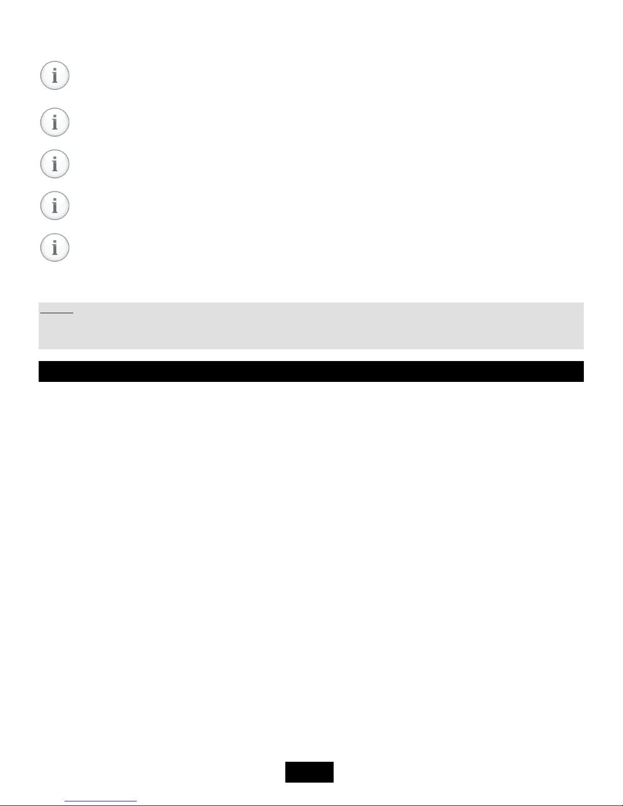
Transmitter functions
The detector's motherboard is equipped by status LEDs, which help in detecting problems during the installation.
LED „POW“ shines at correct power
LED „ALARM“ shines when the alarm level is crossed
LED „ERROR“ shines in case of malfunction or an unstandard situation
1. Turning on the transmitter
Po After turning on the power the LED "POW" starts shining and the LED "ERROR" starts flashing, indicating a forming
sequence of the sensor and automatic testing procedures, which can take up to 180s depending on the sensor used. The
output of the current loop is 1mA. During this sequence, testing of internal electronics and stabilization of the sensor in order
to eliminate false alarms after turning on, is taking place. After completion of the formation, a 4mA current begins to flow on
the output of the current loop and the transmitter starts working according to it's settings.
2. Gas detection
The transmitter continuously measures the detected gas concentration in the atmoshpere and converts it's current value into
a 4-20 mA signal or transmits it's value to the evaluation unit via DEGA protocol.
3. Malfunction
If a malfunction of the electronics or the sensor is found during operation, the transmitter will continue transmitting via
current loop 0,5mA. On the PCB this condition is indicated by the yellow „ERROR“ LED.
4. Monitoring the calibration periods
The transmitter continuously checks the calibration validity of the connected sensor.
After 12 months since the last calibration (Max. calibration interval) the LED "ERROR" starts flashing. The connected sensor
must be calibrated immediately. The transmitter will transmit the information about the ending calibration via current loop.
The transmission will be the following: 10s transmitting a 4-20mA signal informing about the actual gas concentration
following a 1 second interval of 2mA current.
Operation, maintenance, inspection and service of the transmitter
1. Usage limits
To maintain proper operation of the transmitter it is neccesery to respect the fact, that step changes of humidity,
condensation or rapid changes of pressure can cause incorrect indication of the measured value. Each sensing technology is
suited for different methods of application, which is described below. All sensors are characterized by a smaller or larger cross-
sensitivity to other gases than those which are set. Therefore before processing project documentation we recommend to
have the air in the deployment area of the detection system analyzed.
a) catalytic sensors: Trace amount of vapors of silicon compounds and sulfur compounds cause a permanent loss of sensitivity,
which requires recalibration or replacement of the sensor. Longterm crossing of the measuring range causes a decrease in
sensitivity. In case of an atmoshpere having an oxygen content of less than 17%, there will be an underestimaton of the
measured value. In case of an atmoshpere having an oxygen content of more than 25%, there will be an overestimation of the
measured value.
b) electrochemical sensors: Constant exposure to toxic gases or short-term exposure to gases, which greatly exceed the
maximum range of the sensor, can damage the electrochemical sensor, which requires recalibration or replacement. High
temperature along with low relative humidity have a negative effect on the sensor's lifetime. In case of an atmoshpere having
an oxygen content of less than 1% for longer than 1 hour, there will be an underestimation of the measured value.
c) infrared sensors: Vapor acids and alkalis can etch the optical system and distort the measurements. A check or a calibration
may be neccesery.
d) semiconductor sensors: Short-term exposure to gases or vapors of organic solvents, which greatly exceed the maximum
range of the sensor, may damage the sensor and a recalibration or replacement may be required. In case of an atmoshpere
having na oxygen content of less than 18%, there will be an underestimation of the measured value.