aquilar AquiTron AT-MGS-402 Installation instructions

AquiTron
INSTALLATION
& OPERATION
INSTRUCTIONS
AT-MGS-402
Gas Detection Controller

a
AT-MGS-402 User Manual
Contents
Introduction ..................................................... 1
1.1 About this Manual ........................................................................................................... 1
1.2 Conventions...................................................................................................................... 1
1.2.1 Iconography..................................................................................................................................................1
1.3 General Safety Statements............................................................................................. 2
Product Description......................................... 3
2.1 Product Overview ............................................................................................................ 3
2.2 Intended Use .................................................................................................................... 4
2.3 Design Features ............................................................................................................... 4
2.4 Front Panel ....................................................................................................................... 5
2.5 Components ..................................................................................................................... 6
2.6 Communication Features ............................................................................................... 6
Installation ....................................................... 7
3.1 Warnings & Cautions ....................................................................................................... 7
3.2 Preliminary Inspection.................................................................................................... 7
3.3 Suitable / Appropriate Locations ................................................................................... 7
3.4 Mounting the Gas Detection Controller........................................................................ 8
3.5 Power Wiring .................................................................................................................... 8
3.5.1 Connecting the Main (100-240 VAC) Power...............................................................................................8
3.6 Sensor Output & Modbus Connections......................................................................... 9
3.6.1 AT-MGS-402 Gas Detection Controller Network .......................................................................................9
3.6.2 Integration with Building Management System .....................................................................................11
3.7 Connecting External Alarms ......................................................................................... 11
3.7.1 Overview......................................................................................................................................................11
3.8 Reinstalling AT-MGS-402 Lid ......................................................................................... 12

b
AT-MGS-402 User Manual
Operation........................................................ 14
4.1 Overview ......................................................................................................................... 14
4.1.1 Main Function.............................................................................................................................................14
4.1.2 Power Up.....................................................................................................................................................14
4.1.3 Channel number keys................................................................................................................................14
4.2 Controller Setup............................................................................................................. 14
4.2.1 Modbus Setup.............................................................................................................................................14
4.2.2 Relay Setup .................................................................................................................................................16
4.3 Gas Detection System Test ........................................................................................... 17
Modbus............................................................ 19
5.1 Modbus Overview.......................................................................................................... 19
5.1.1 SLAVE NODE ADDRESS ...............................................................................................................................19
5.1.2 SLAVE BAUD RATE.......................................................................................................................................19
5.1.3 SLAVE PARITY .............................................................................................................................................19
5.1.4 SLAVE STOP BIT...........................................................................................................................................19
5.1.5 SLAVE TERMINATION .................................................................................................................................19
5.2 Modbus Registers .......................................................................................................... 19
Diagnostics & Troubleshooting .................... 24
6.1 FAULT CODES.................................................................................................................. 24
Additional Information ................................. 25
7.1 Disposing of Instrument ............................................................................................... 25
7.2 TechnicalSpecications................................................................................................ 25
Parts and Accessories.................................... 27
8.1 Part Numbers................................................................................................................... 7
1
AT-MGS-402 User Manual
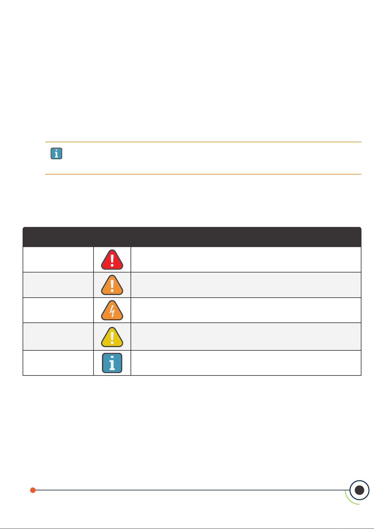
Alert Icon Description
DANGER Imminently hazardous situation which, if not avoided, will result in death or
serious injury.
WARNING Potentially hazardous situation which, if not avoided, could result in death or
serious injury.
WARNING Potential electrical shock hazard which, if not avoided, could result in death
or serious injury.
CAUTION
Potentially hazardous situation which, if not avoided, could result in physical
injury or damage to the product or environment. It may also be used to alert
against unsafe practices.
IMPORTANT Additional information on how to use the product.
IMPORTANT:Before using this product, carefully read and strictly follow the instructions in the
manual. Ensure that all product documentation is retained and available to anyone operating
the instrument.
1. Introduction
1.1 About this Manual
Thank you for investing in an AquiTron AT-MGS-402 Gas Detector Controller. To ensure operator safety and
the proper use of the controller, please read the contents of this manual for important information on the
operation and maintenance of the instrument.
1.2 Conventions
1.2.1 Iconography
2
AT-MGS-402 User Manual
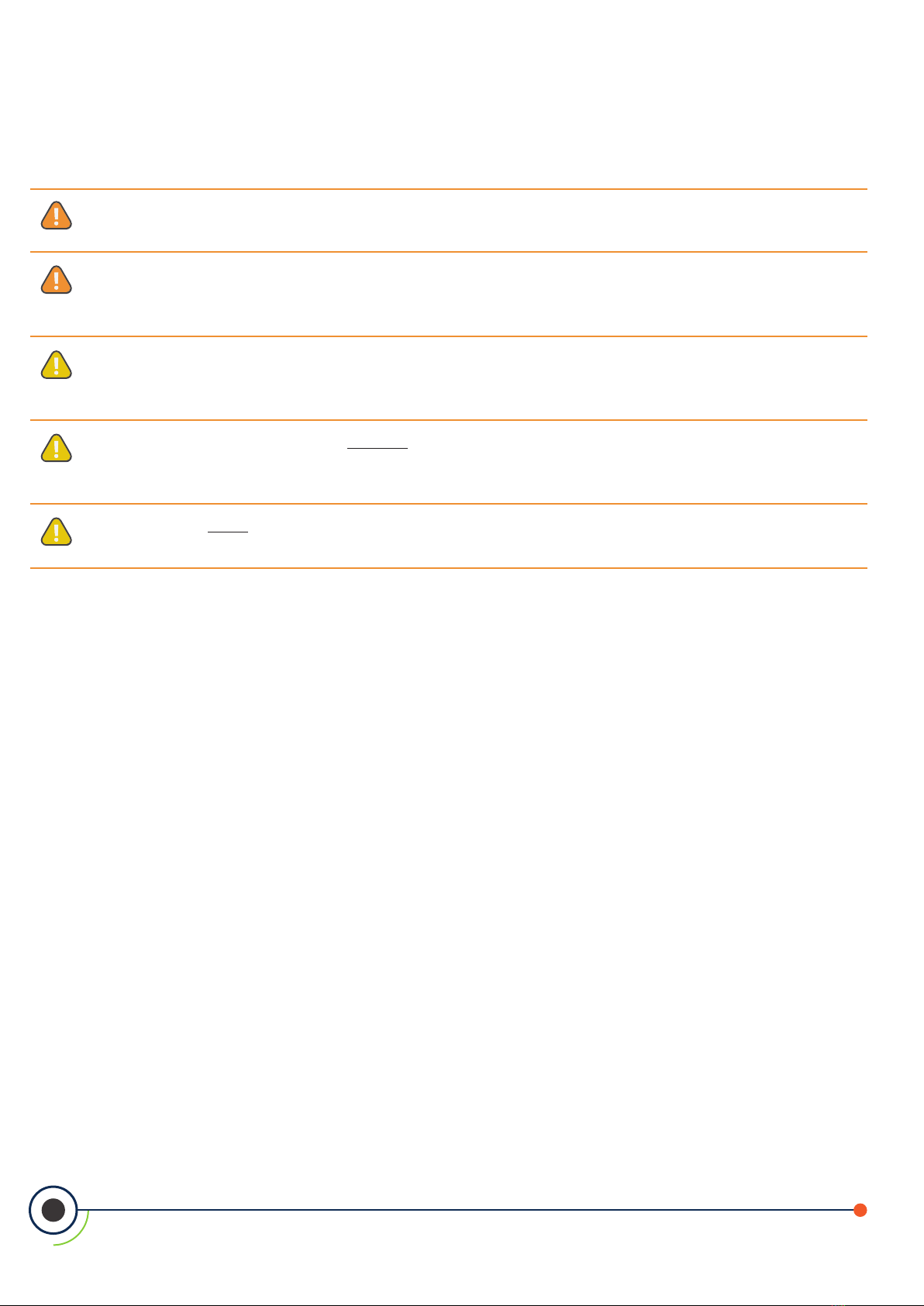
1.3 General Safety Statements
DANGER:This instrument is neither certied nor approved for operation in oxygen-enriched atmospheres
and / or hazardous locations. Failure to comply may result in personal injury or death.
CAUTION: The protection provided by this product may become impaired if it is used in a manner
not specified by the manufacturer. Modifications to this instrument, not expressly approved, will
void the warranty.
CAUTION: In case of malfunction, DO NOT continue to use this equipment if there are any symptoms of
malfunction or failure. In the case of such occurrence, de-energize the power supply and contact a qualied
repair technician or contact Aquilar on 01403 216100.
CAUTION: Use ONLY the provided cable glands for electrical and communication wiring. Drilling into the
box will void the warranty.
WARNING: Always remove AC power before working inside the AT-MGS-402 enclosure and exercise
extreme care when accessing the products interior. Only qualied electrical maintenance personnel should
perform connections and adjustments.
3
AT-MGS-402 User Manual
2. Product Description
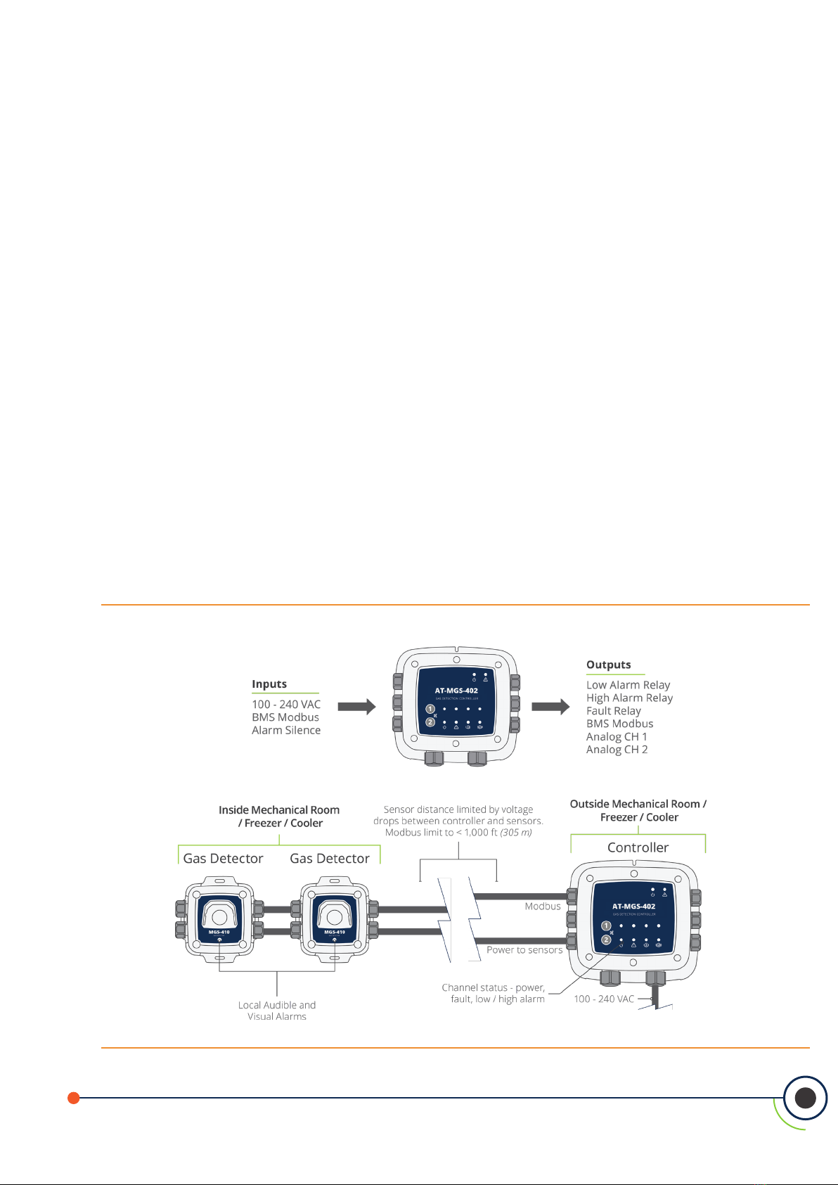
2.1 Product Overview
The AT-MGS-402 Gas Detection Controller displays centralized information about the status of connected
AT-MGS-410 gas detectors. The AT-MGS-402 is connected to the AT-MGS-410s via Modbus RTU.
The AT-MGS-402 can be used to provide power to each connected AT-MGS-410 gas detector, negating the
need for separate power supply at the location of the gas detector.
The AT-MGS-402 displays status via a bank of LEDs that represent the channel/sensor connected to it. Each
channel/sensor has a row of dedicated LEDs to indicate the status of the sensor:
Power Fault Low alarm High alarm
The AT-MGS-402 provides three relays (fault, low and high alarm status) for connection to auxiliary systems,
ventilation or other equipment.
The AT-MGS-402 has an integrated visual alarm of LEDs around the perimeter of the controller that will
activate when a low or high alarm is received from either channel. In addition, the integrated audible alarm
will activate in the same manner.
In addition to being a Modbus master to the AT-MGS-410 gas sensors, the AT-MGS-402 acts as a Modbus
slave for ease of integration into a building automation system (BMS) or programmable logic controller (PLC).
The controller also features two analog outputs which may enable monitoring gas detector levels remotely.
Figure 2-1 - The AT-MGS-402 Gas Controller System
4
AT-MGS-402 User Manual
WARNING: This instrument is neither certied nor approved for operation in oxygen-enriched
atmospheres. Failure to comply may result in EXPLOSION.
WARNING: For your safety, DO NOT use this instrument in locations classied as hazardous
because it has not been designed for such areas.
2.2 Intended Use
The AT-MGS-402 provides audio-visual alerts and information pertaining to the status of a centralized gas
detector network. This information allows concise, at-a-glance notication of any alarm or fault status
regarding a connected gas detector located outside the monitored space, as required by industry safety
standards (BS EN 378, ASHRAE 15).
2.3 Design Features
Power options 100 - 240 VAC, 50/60 Hz, 20 W (max.)
Provides power for up to (2) AT-MGS-410 AquiTron gas detectors
Output/
Communications
RS485 Modbus RTU Master for Gas Detectors
RS485 Modbus RTU Slave for BMS
Diagnostic/status LEDs
• Controller (power, fault)
• Gas detectors (power, fault, low alarm, high alarm)
Congurable output options
• 3 × relays (fault, low alarm, high alarm)
• 2× Analog outputs (4-20 mA, 1-5 V or 2-10 V)
Integrated high output visual strobe
Integrated high output audible alarm
Remote silence input (In addition to silence on the on the controller input.)

5
AT-MGS-402 User Manual
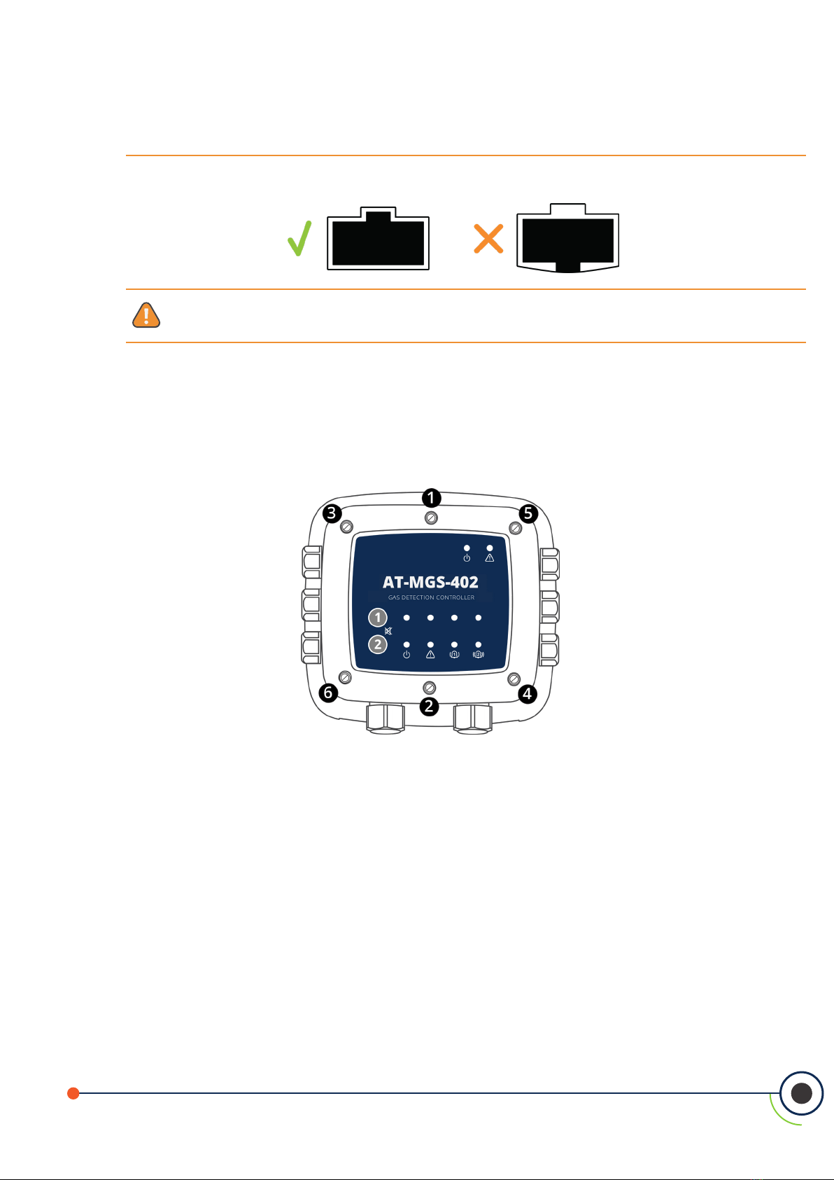
2.4 Front Panel
Figure 2-2 - Front Panel Layout
# Front Panel Description
1 Integrated visual alarm in bezel
2 Controller Power & Fault LEDS
3 Channel 1 and 2 mute alarm buttons
4 Power, Fault, Low Alarm, High Alarm LEDs; each channel
5 M16 Cable Glands (×6)
6 M20 Cable Glands (×2)

6
AT-MGS-402 User Manual
2.5 Components
Figure 2-3 - AT-MGS-402 Layout
# Component Description # Component Description
1 Analog Outputs (×2) 8 Low Alarm Relay
2 Modbus to Gas Detectors 9 AC Power Line Input
3 Modbus to BMS 10 Power Supply
4 Remote Silence 11 Sensor Power Connections (×2)
5 Audible Alarm 12 M20 Cable Glands (×2)
6 Fault Relay 13 M16 Cable Glands (×6)
7 High Alarm Relay
2.6 Communication Features
The AT-MGS-402 Gas Detection Controller features full two-way communications via an RS-485 interface.
Modbus RTU is the communication protocol standard.
The controller is congured as a Modbus master and can be the centralized controller for a two sensor gas
network and also has a Modbus slave port for connection to a BMS / re safety panel for a complete gas
detection solution.

7
AT-MGS-402 User Manual
3. Installation
3.1 Warnings & Cautions
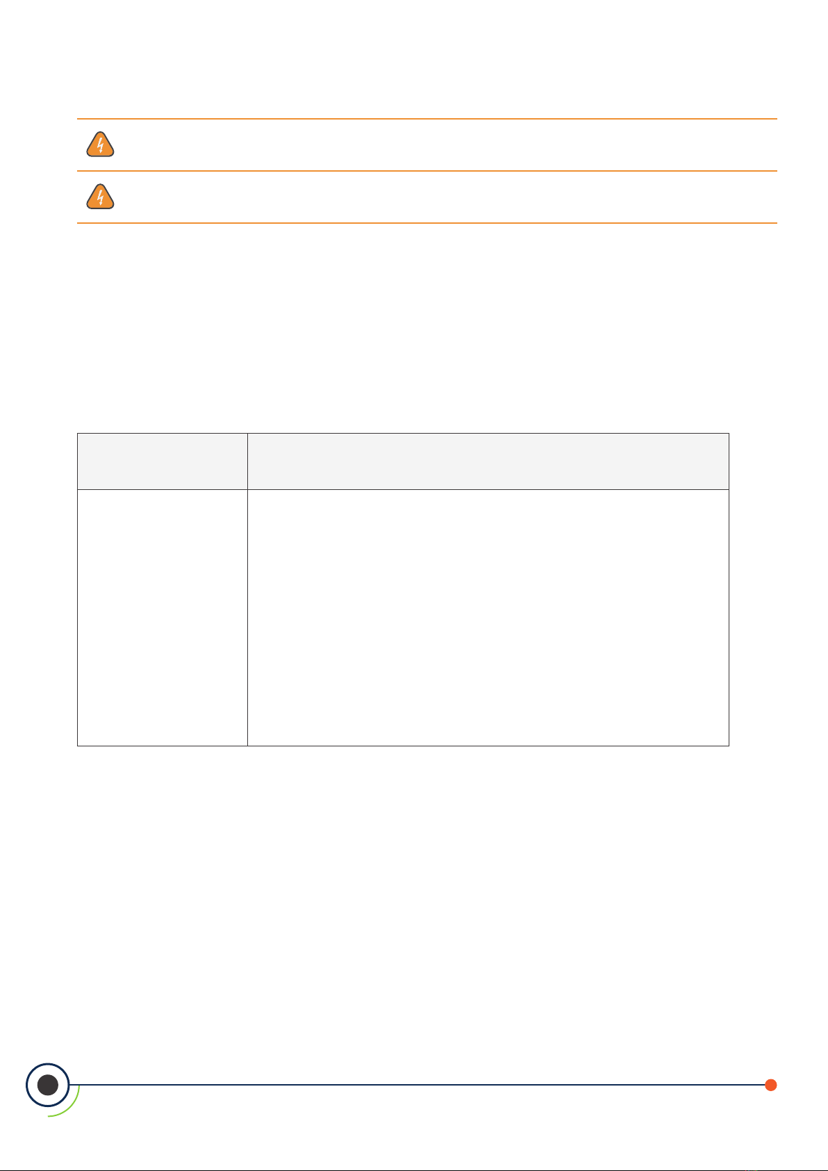
WARNING: Explosion hazard! Do not mount the AT-MGS-402 Gas Detection Controller in an area
that may contain ammable liquids, vapors or aerosols. Operation of any electrical equipment in
such an environment constitutes a safety hazard.
WARNING: Electrical installation should be performed by a certied electrician, and should comply
with all applicable NEC / CEC and local electrical safety codes.
WARNING: Shock hazard! Always turn o AC power before working inside the monitor.
CAUTION: Drilling holes in the AT-MGS-402 Gas Detection Controller enclosure may damage the
unit and will void the warranty. Please use provided cable glands for electrical connections.
CAUTION: The AT-MGS-402 Gas Detection Controller contains sensitive electronic components
that can be easily damaged. Be careful not to touch or disturb any of these components.
3.2 Preliminary Inspection
The AT-MGS-402 Gas Detection Controller has been thoroughly inspected and tested prior to shipment from
the factory. Nevertheless, it is recommended that the instrument be re-checked prior to installation. Inspect
the outside of the enclosure to make sure there are no obvious signs of shipping damage. Remove the top
of the enclosure. Visually inspect the interior of the enclosure for loose wires or components that may have
become dislodged during shipment. If damage is discovered, please contact a qualied repair technician or
contact Aquilar for assistance.
3.3 Suitable / Appropriate Locations
The AT-MGS-402 Gas Detection Controller is design for use in a small gas detection network that could be in
mechanical rooms, warehouses, cold storage or freezers to help comply with international safety standards
(BS EN 378, ASHRAE 15, CSA-B52). The AT-MGS-402 is a NEMA 4X (poly carbonate) or IP66 rated enclosure and
can be placed in environments from -40 OC to +50 OC ambient temperatures. Typical installations would be either
inside or outside the door of an enclosed space to have local audible and visual alarms as required by safety
standards.
The AT-MGS-402 is not intended for installation in classied locations.
8
AT-MGS-402 User Manual
3.4 Mounting the Gas Detection Controller
NOTE: A certied AC power disconnect or circuit breaker should be mounted near the controller
and installed following applicable local and national codes. If a switch is used instead of a circuit
breaker, a properly rated CERTIFIED fuse or current limiter is required to be installed as per local or
national codes. Markings for positions of the switch or breaker should state (I) for on and (O) for o.
WARNING: DO NOT allow the lid / sensor to hang from the ribbon cable. Failure to comply may
result in damage to the product.
1. Mount the AT-MGS-402 according to the product dimensions, maximum wiring lengths and
following considerations:
• Environment: the full range of environmental conditions when selecting a location.
• Application: the specics of the application (possible leaks, air movement / draft, etc.)
when selecting a location.
• Accessibility: the degree of accessibility required for maintenance purposes when
selecting a location.
2. Using a 4 mm hex key / allen wrench (not included) remove the lid and disconnect the ribbon
cable from the base.
3. Set the lid and rubber gasket aside to be reinstalled later.
3.5 Power Wiring
3.5.1 Connecting the Main (100-240 VAC) Power
The AT-MGS-402 controller features (2) M20 cable glands (item 12 in “Figure 2-3 - AT-MGS-402 Layout” on page
7) that are intended for power entry / wiring.
WARNING: Copper conductors for connection to main power supply and output relays must be
made in accordance with local building codes.
Locate the AC power input terminal block (item 9 in “Figure 2-3 - AT-MGS-402 Layout” on page 7) and remove it
from the controller.
4. Ensuring that the main power is turned o at the upstream circuit breaker or disconnect
switch, feed the incoming power leads through one of the M20 glands and into the appropriate
terminals (L (Live) – brown, E (Earth) – green, N (Neutral) – blue) on the terminal block.
9
AT-MGS-402 User Manual
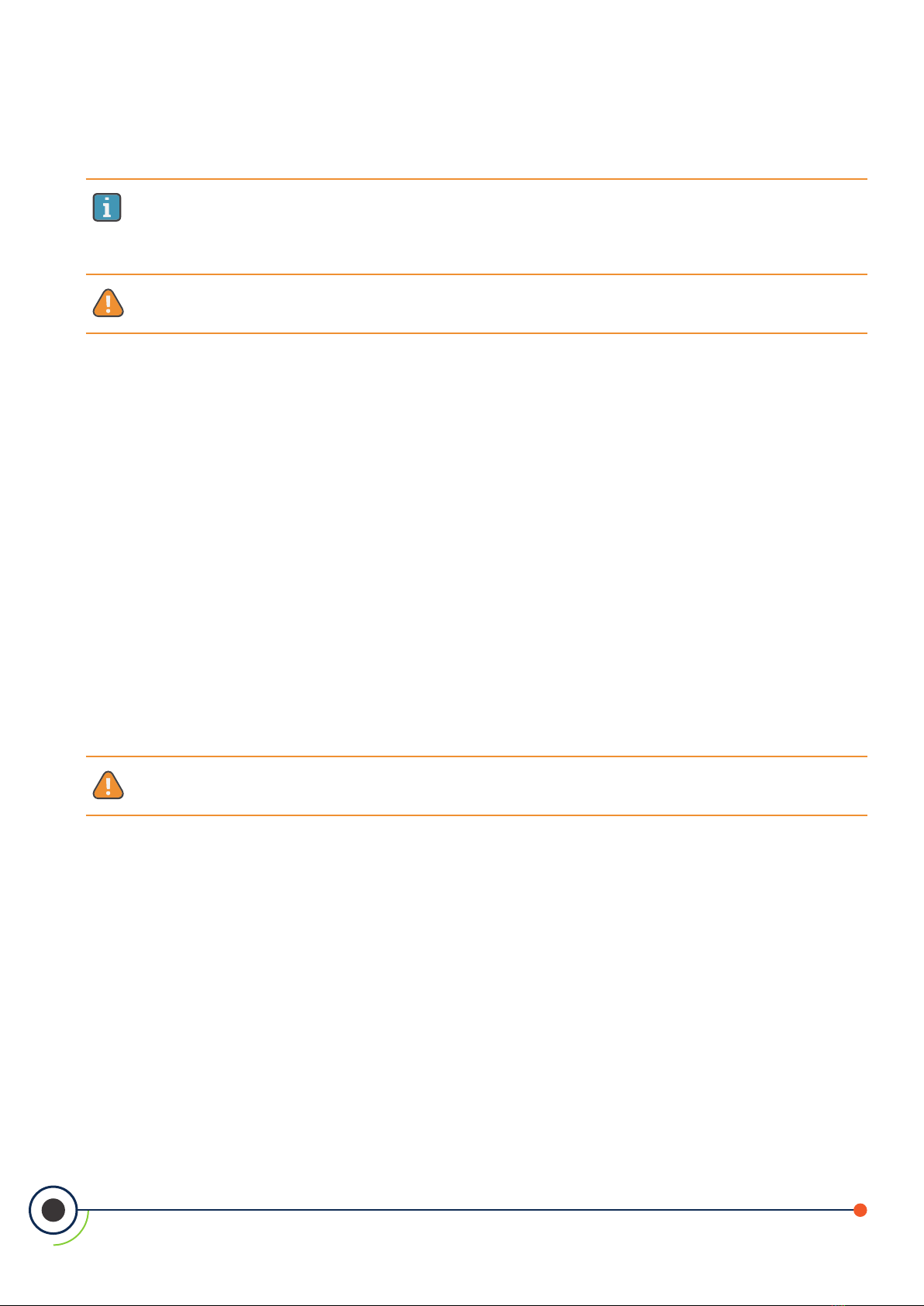
5. Plug the power terminal block back into the printed circuit board (PCB).
Figure 3-1 - Power Terminal Block
LEN
3.6 Sensor Output & Modbus Connections
3.6.1 AT-MGS-402 Gas Detection Controller Network
The AT-MGS-402 Modbus communications network is connected to the AT-MGS-410 gas detectors using
a shielded twisted pair instrument cable (Belden 3106A or equivalent). The same type of cable can be used
for power connection when using the AT-MGS-402 controller as the power source (+24VDC) for the AT-
MGS-410 gas sensors and standard Modbus network limits. Care needs to be taken to account for voltage
drops between the controller and the AT-MGS-410 gas sensors and standard Modbus network limits. The
furthest distance the AT-MGS-410 can be from the AT-MGS-402 controller is 305M when using 20 - 16AWG
conductors for the sensor power and Modbus connections.
3.6.1.1 Connecting the +24 VDC Terminal Block:
When using the AT-MGS-402 as the +24VDC power source of the AT-MGS-410 gas sensors the power should
be connected the following manner.
1. Locate the +24 VDC terminal block in the AT-MGS-402 controller (item 11 in “Figure 2-3 - AT-
MGS-402 Layout” on page 7).
2. Using Belden 3106A or equivalent control wire feed through one of the available cable glands
and connect the ‘+’ and ‘-‘ terminals to the appropriate terminals in the AT-MGS-402.
NOTE: Refer to the AT-MGS-410 User Manual or QSG for location and connection of the
corresponding +24 VDC terminal block in the AT-MGS-410 gas sensor.
10
AT-MGS-402 User Manual
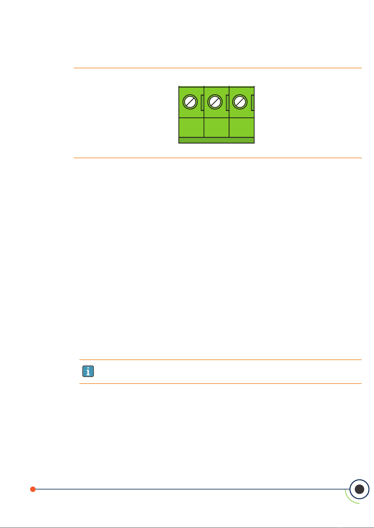
3. Reconnect +24VDC terminal to the PCB and repeat for a second AT-MGS-410 gas sensor if
needed.
Figure 3-2 - +24 VDC Terminal Block
-
+
3.6.1.2 Connecting the Modbus network from the AT-MGS-402 to the AT-
MGS-410
1. Locate the Modbus/Sensor terminal block in the AT-MGS-402 controller (item 2 in “Figure 2-3 -
AT-MGS-402 Layout” on page 7).
2. Using one of the M16 cable glands feed the Belden 3106A or equivalent cable through the
cable gland and connect to the Modbus/Sensor terminal in the following manner.
3. Connect one lead to of the twisted pair (note wire color) to the ‘B’ terminal.
4. Connect the second lead of the twisted pair to the ‘A’ terminal (note wire color).
5. Connect the ground to the ‘GND’ terminal and then connect the shield or drain lead to the
‘SH’ terminal.
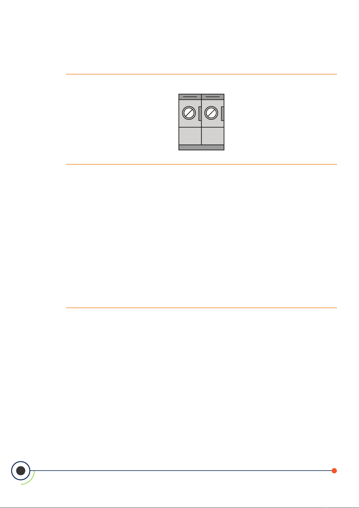
6. Replace the terminal block into the AT-MGS-402 controller.
Figure 3-3 - MODBUS/Sensor Terminal Block
11
AT-MGS-402 User Manual
BAGND SH
Refer to the AT-MGS-410 User Manual or Quick Start Guide for location and connection of the corresponding
Modbus terminal block in the AT-MGS-410 gas sensor.
NOTE: Ensure that the corresponding wire colors noted above are connected to the correct ‘B’ and
‘A’ terminals in the Modbus terminal block in the AT-MGS-410 gas sensor and the ground and drain
are properly terminated according to Modbus protocol.
3.6.2 Integration with Building Management System
A second Modbus connection is available in the AT- MGS-402 to connect to a Building Management System
(BMS). The physical connections are made the same as described above in section 3.6.1 but using the
Modbus/BMS terminal block (item 3 in “Figure 2-3 - AT-MGS-402 Layout” on page 7).
1. Locate the Modbus / BMS terminal block in the AT-MGS-402.
2. Feed Belden 3106A or equivalent cable through one of the M16 cable glands (item 13 in “Figure
2-3 - AT-MGS-402 Layout” on page 7) and connect to the appropriate terminals noting the
color of the wire.
3. Make similar connections to the BMS noting wire color.
4. Controller/BMS Modbus conguration will need to be completed in section 4.2, Controller Setup.
3.7 Connecting External Alarms
3.7.1 Overview
In addition to the integrated visual and audible alarms there are several outputs available in the AT-MGS-402 to
interface with external ventilation, external equipment or for connection to a BMS or buildings re safety panel.

12
AT-MGS-402 User Manual
There are (3) form C relay contacts rated 10A at 240VAC and (2) Analog Outputs (4-20ma, 1-5V, 2-10V). In
addition there is (1) Remote Silence input to interface with a momentary push button that may be in a
dierent location than the AT-MGS-402. See items 1 (Analog outputs), 7-9 (Form C Relays) and 4 (Remote Silence)
in “Figure 2-3 - AT-MGS-402 Layout” on page 7.
The additional outputs should be wired in the same manner as the power and Modbus connections. Use
appropriate conductor sizes on the form C relays that adhere to local building codes. The remote silence
and analog outputs can be wired using Belden 3106A or equivalent cable.
NOTE: The relay contacts are rated 10A at 250VAC resistive load.
3.8 Reinstalling AT-MGS-402 Lid
WARNING: DO NOT leave excess cable inside the gas detector housing. Failure to comply may
result in damage to the product.
CAUTION: When installing the sensor ribbon cable, care must be taken to ensure the proper
orientation of the connector at both ends of the cable. Failure to ensure proper orientation may
result in loss of functionality and/or product damage.
NOTE: To achieve proper seal, the lid screws should be torqued to 15 to 20 lbf in (1.5 to 2.0 Nm.)
Reinstall the rubber gasket. Ensure that it is correctly seated by placing the side with two grooves face down
and the edge with two bumps on the top.
Figure 3-4 - Rubber Gasket
13
AT-MGS-402 User Manual
5. Reconnect the ribbon cable from the sensor to the PCBA as shown.
Figure 3-5 - Ribbon Cable Orientation
WARNING: DO NOT allow the lid / sensor to hang from the ribbon cable. Failure to comply
may result in damage to the product.
6. Ensure no cables are interfering with the sensor module and close the lid. Using a 4mm hex
key / allen wrench, tighten the lid screws in an “X” tightening pattern:

14
AT-MGS-402 User Manual
4. Operation
4.1 Overview
4.1.1 Main Function
Every second the AT-MGS-402 Gas Detection Controller collects gas concentration and status information
from each connected gas detector. Connection status, fault and alarm conditions are indicated by the LED
matrix for each channel. Detector data and controller status information can also be communicated via
Modbus, to a master or BMS device.
4.1.2 Power Up
During power up the perimeter visual alarm and the audible alarm will both run through a test cycle.
The green Power LED for the controller (See item 2, “Figure 2 - Front Panel Layout” on page 7) will illuminate.
When the AT-MGS-402 establishes communications with the AT- MGS-410 controllers the Fault LED for the
controller (item 2, “Figure 2 - Front Panel Layout” on page 7) will go from amber to not illuminated. It can take
up to 5 minutes for the AT-MGS-410 Gas Detectors to warm up.
4.1.3 Channel Number Keys
Pressing a channel number key for ve-seconds on the front panel of the AT-MGS-402 will silence an audible
alarm for 30-minutes. After which time, AT-MGS-402 will re-alarm or reset depending on whether the alarm
condition still remains.
4.2 Controller Setup
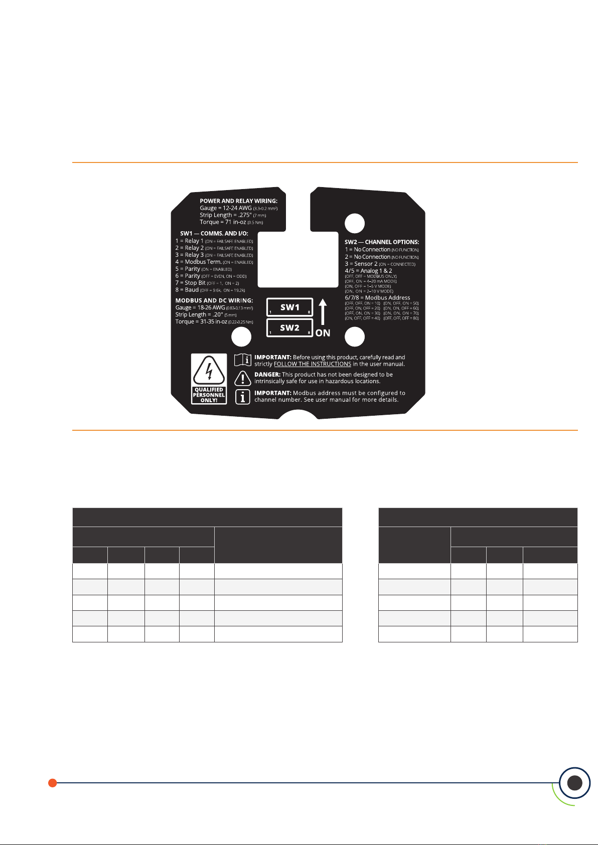
4.2.1 Modbus Setup
Congure AT-MGS-402 to BMS. If using the AT-MGS-402 to interface with a BMS as a slave the Modbus
protocol needs to be congured. (Refer to “Figure 2-3 - AT-MGS-402 Layout” on page 6.)
15
AT-MGS-402 User Manual
Figure 4-1 - AT-MGS-402 Back of Lid Label
Using switch 1 (SW1) on the underside of the lid of the controller use setting 4 to acknowledge whether
the AT-MGS-402 will need to have the terminating resistor engaged. Please see Modbus protocol for best
practice.
Switch 1 Switch 2
MODBUS Setting Action MODBUS
Address
Setting
5 6 7 8 6 7 8
OFF Parity Disabled 10 OFF OFF ON
ON Parity Enabled 20 OFF ON OFF
OFF Even Parity 30 OFF ON ON
ON Odd Parity 40 ON OFF OFF
OFF 1 Stop Bit 50 ON OFF ON

16
AT-MGS-402 User Manual
ON 2 Stop Bits 60 ON ON OFF
OFF 9600 Bits Per Second 70 ON ON ON
ON 19200 Bits Per Second 80 OFF OFF OFF
NOTE: All of the above settings must match the BMS system to work correctly.
4.2.2 Relay Setup
Additional hardware conguration.
4.2.2.1 Form C Relays
The (3) form C relays that are included in the AT-MGS-402 (fault, low alarm, high alarm) can be congured to
be fail safe (if power is lost on the relay it will be set to its fault or alarm state until power is restored). The fail safe
mode can be congured for each of the individual relays and is done using SW1 settings 1, 2 and 3. If fail
safe mode is desirable for the form C relays change settings to ON.
4.2.2.2 Multiple MGS Gas Sensors
Switch 2 setting 3 is enabled if a second AT-MGS-410 sensor will be connected to the AT-MGS-402 (one sensor is
default).
4.2.2.3 Analog Outputs
The (2) analog outputs can be congured to 4-20mA, 1-5V or 2-10V depending on preference. When
congured both analog outputs will be congured the same (i.e., both 4-20mA, both 1-5V or both 2-10V). Using
SW2 settings 4 and 5 set the desired conguration.
Condition 4-20 mA 1-5V 2-10V
Oine, Warmup 3 mA 0.75V 1.5V
Fault 1 mA 0V 0V
Under-range 3.8 mA 0.95V 1.9V

17
AT-MGS-402 User Manual
Over-range 20.5 mA 5V 10V
Normal 4-20 mA 1-5V 2-10V
IMPORTANT: The Analog outputs come with a jumper installed from the factory. This ensures
that the AT-MGS-402 does not go into alarm mode upon power but before connecting the analog
outputs – no signal or very small signal is a communications fault. Remove these jumpers after
conguring the analog outputs.
4.3 Gas Detection System Test
After installation and power-up of the AT-MGS-402 Controller, one should verify that the instrument and
connected devices are functioning as intended. The following steps should be considered in the commissioning.
1. Inspect the AT-MGS-402 Controller and verify the following:
Figure 4-2 - Inspecting the AT-MGS-402
AT-MGS-402
AT-MGS-410
Power LED is solid GREEN
Fault LED is OFF
AT-MGS-402
AT-MGS-410
No Audio Alarm
Channel Power LEDs are BLINKING
Channel Fault / Alarm LEDs are OFF
2. Inspect connected AT-MGS-410 Gas Detector(s) and verify the following:
Figure 4-3 - Inspecting Connected AT-MGS-410
Table of contents
Other aquilar Gas Detector manuals


