RD MBA1 0001 SE 021413B4 301012
2 (1*/,6+
:,5,1*',$*5$0
)LJ Wiring diagram of a single detector with a manual
reset 230V ~ normally open solenoid valve.
NL 345
E.V.
230V~ N.O.
230V~
LN
230V~
)LJ Wiring diagram of a detector with a manual reset
230V ~ normally closed solenoid valve.
NL 345
230V~ N.C
E.V.
LN
230V~
230V~
LN345
230V~
)LJ Wiring diagram of a detector without solenoid valve.
:$51,1*
7+(*$6'(7(&7250867%(32:(521/<%<7+(32:(5&25'&211(&7('72
7+('(9,&(
,) 7+( ,167$//$7,21 ,1&/8'( $/62 $ 62/(12,' 9$/9( (/(&75,&$/ 6$)(7< $1' '(9,&(
)($785(6 $5( *8$5$17((' 21/< ,) 7+( (/(&75,&$/ &211(&7,216 $5( 0$'( :,7+ $
),;(':,5,1*7+528*+7+(%2772023(1,1*6217+(3/$67,&%$6(,1',&$7(':,7+7+(
$552:,1),*85(627+$77+(,33527(&7,21'(*5((,6127$))(&7('
)LJ
7(&+1,&$/)($785(6
Power supply: 230V~ -15% +10% 50/60Hz
Power absorption: 2VA
Sensor type: SnO2semiconductor replaceable
Detected gas: BEAGLE L : LPG
BEAGLE M: Methane
Alarm threshold: 10% L.E.L.
Contacts rating: 5A @ 250V~ SPDT
Indicators: Active: Green led on
Fail: Yellow led on
Alarm: Red led on
Alarm: Buzzer
Heating delay at turn-on: ~ 30 seconds
Relay activation delay: ~ 5 seconds
Sensor lifetime: 5 years
Operating temperature: 0°C .. 40°C
Storage temperature: -10°C .. +50°C
Humidity limits: 20% .. 80% RH
(non condensing)
Protection rating: IP 42
Case: Material: ABS V0 self-extinguishing
Color: Signal white (RAL 9003)
Size: 85 x 107 x 38 mm
(W x H x D)
Weight: ~ 260 gr.
Product Reference Standard: CEI-EN 50194-1 (2009)
EMC Reference Standard: CEI-EN 50270 (2000)
LVD Reference Standard: CEI-EN 60335-1 (1994)
23(5$7,21
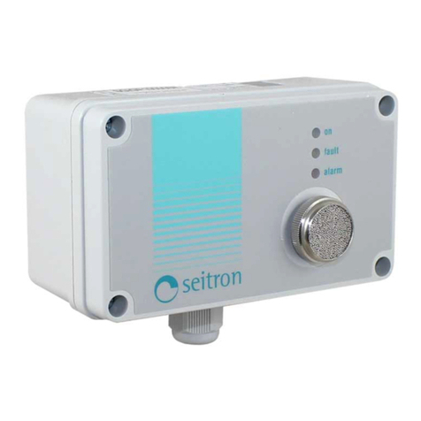
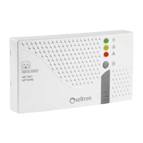
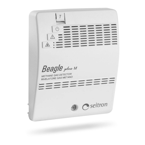
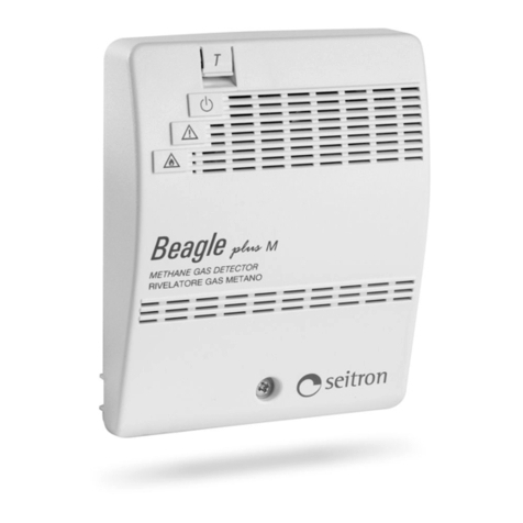
This device (Fig. 1) is a flammable gas leakage domestic
detector. When exposed to a gas concentration much
lower than the danger level, the detector turns on a red
light and a buzzer, then, after 5 seconds it, turns on a relay
which can be used to stop the gas supply.
Note: The user might smell the presence of gas before the
detector does; this happens because the distribution
companies use to add odorizers to natural gas and LPG.
This sensation is extremely variable from person to person,
and depends on the exposure time.
To test the correct operation of the detector, press the T
(Test) button on the frontal panel: the green, yellow and
red LEDs will turn on; the buzzer will buzz and after 5
seconds the relay contact is activated.
The device is equipped with a delay line which avoids the
intervention of the alarm system (in order for the gas
sensor to heat up) whenever the device is turned on or
even after a mains black-out, as soon as the power comes
back. After that delay (about 30 seconds) the yellow LED
turns off and the green LED remains on to show that the
detector is powered.
The device features an auto-diagnostics system which
verifies the sensor reliability.
When the yellow indicator is turned on (sensor fail) the
possible causes must be searched among the following:
- sensor fail;
- sensor disconnected;
- detector malfunctioning.
,167$//$7,21
This device is intended for wall mount only.
To access the internal parts, unscrew the screw and remove
the front panel (Fig. 2).
The power supply of the unit is solely intended to be through
the connected power cord.
If the installation needs also the connection of a load, it will
be necessary to remove, with a screwdriver, the plastic part
indicated by the arrow in Fig 3, to pass the cables of the
fixed wiring. Then do the wiring as proposed in diagram of
Fig. 5 or 6.
Please note that the intervention delay is strictly dependant
both on a correct positioning of the detector in the room and
to the type of gas to be detected.
In case of 'heavy' gases (as for LPG) an installation in low
places is advisable (about 30 cm from floor level), meanwhile
for ’light’ gases like methane in high places (about 30 cm
from ceiling level).
Please avoid to install this gas detector in any position in
which its operational features could be compromised, such
as the following:
- in an enclosed space (e.g. in a cupboard or behind a
curtain;
- directly above a sink;
- next to a door or window;
- next to an extractor fan;
- in an area where the temperature may drop below - 10°C
or exceed + 40°C;
- where dirt and dust may block the sensor;
- in a damp or humid location.
Do not use the following substances in the device
immediate adjacency:
- alcohol, fuels
- solvents and diluents
- adhesives, silicones products and colours
- cleaning detergents
- perfumes
- spray products in general
Clean the device only using a cloth damped with water.
In order to grant a real safety, a gas detector must be
coupled to an electro-valve capable of blocking the gas flow
in the event of an alarm.
Both the gas unit and the solenoid valve must comply with
the law prescriptions in force in the country concerned.
BEAGLE detector can be connected to two types of electro-
valve:
- 230V~ Normally Open electro-valve;
- 230V~ Normally Closed electro-valve;
In order to check the proper efficiency of the device sensor
a specific test gas bottle (optional) is made available which
must be used according to the enclosed instructions.
:$51,1* $Q\ RWKHU PHWKRG IRU WHVWLQJ VXFK DV WKH
XVH RI FLJDUHWWH OLJKWHUV IODPPDEOH YDSRXUV HWF FDQ
OHDGWRZURQJFRQFOXVLRQVDVZHOODVWRWKHLUUHYHUVLELOH
GDPDJHRIWKHVHQVRULWVHOI
:$51,1*
The installer is reminded to fill in and apply the sticking label
supplied with the product by writing the installation date of
the product, the date before which the sensor module must
be replaced, the date before which the sensor module must
be replaced the second and last time and finally the date
before which the entire detector must be replaced.
The latter is stated on 15 solar years from the installation
date of the product.
This label must be applied, at installer care, on a visible side
of the gas detector once it has been fixed in its typical
installation position.
Warning label:
RD MBA1 0001 SE 021413C4 301012
3 (1*/,6+
