S&S Merlin 1500S User manual
Merlin 1500S User Guide
Rev: 07 05-19 1
Gas Safety Products
Merlin 1500S
Gas & Ventilation Interlock system
User Guide
Please read this guide carefully and retain for future use.

Merlin 1500S User Guide
Rev: 07 05-19 2
Table of contents
1General Information............................................................................................3
1.1 Panel Mounting...............................................................................................................3
2Circuit Board Terminals.......................................................................................4
4
2.1 POWER..............................................................................................................................4
2.2 GAS VALVE ......................................................................................................................4
2.3 SUPPLY FAN & EXTRACT FAN PD SWITCHES...................................................................4
2.4 BMS OUT ...........................................................................................................................4
2.5 EM REMOTE ......................................................................................................................4
2.6 GAS DETECTOR................................................................................................................5
2.7 FS 1/2/3/4 .........................................................................................................................5
2.8 CO2 MONITOR.................................................................................................................5
2.9 12V DC .............................................................................................................................5
3Installation & Operation ......................................................................................6
3.1 System ON and OFF........................................................................................................6
3.2 Emergency Shut Off........................................................................................................6
3.3 BMS integration ...............................................................................................................6
3.4 Fan Switch Integration....................................................................................................6
3.5 Fire alarm integration .....................................................................................................7
4Panel LED status...................................................................................................7
5Maintenance .......................................................................................................8
61500S Wiring Spec ..............................................................................................9
7Manufacturer’s Warranty ..................................................................................12
Merlin 1500S User Guide
Rev: 07 05-19 3
1General Information
The Merlin 1500S is a gas and ventilation interlock panel.
The Merlin 1500S can receive connections from up to four external remote air pressure
differential switches or current monitors, remote emergency shut-off buttons, gas detectors and
a Merlin CO2monitor. It can also be integrated with a BMS and fire alarm.
It is recommended that the user reads this guide before using the system. Please do NOT
attempt to operate the unit until the contents of this document have been read and are
thoroughly understood.
1.1 Panel Mounting.
The control panel is designed for surface mounting using 4 mounting screws. Removing the cover
on the panel gives access to the circuit board.
The PCB should be removed before drilling entry holes into the case.
Important Warning Statements
Never ignore your device when in alarm.
This device requires a continual supply of electrical power –it will not work without power.
This device should not be used to substitute proper installation, use and/or maintenance of fuel burning
appliances including appropriate ventilation and exhaust systems.
Your product should reach you in perfect condition, if you suspect it is damaged, contact your supplier.
Information on waste disposal for consumers of electrical & electronic equipment. (EEE)
When this product has reached the end of its life it must be treated as Waste Electrical & Electronics Equipment
(WEEE). Any WEEE marked products must not be mixed with general household waste, but kept separate for the
treatment, recovery and recycling of the materials used.
Please contact your supplier or local authority for details of recycling schemes in your area.
Merlin 1500S User Guide
Rev: 07 05-19 4
2Circuit Board Terminals
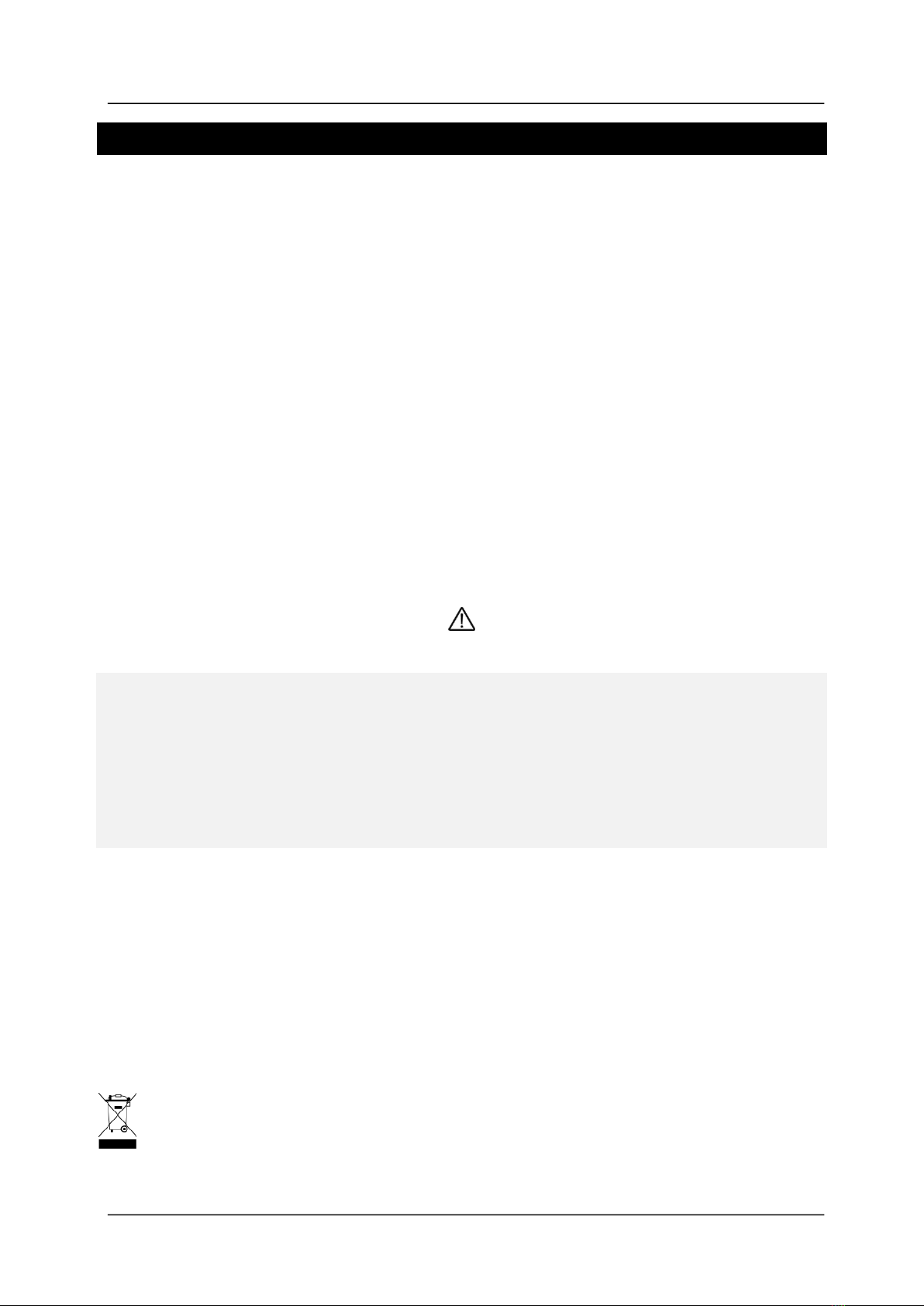
2.1 POWER
A 110-240VAC electrical supply should be externally fused at 3A
and connected to the terminals marked [POWER LNE].
2.2 GAS VALVE
The 110-240VAC gas solenoid valve should be powered using the
terminals on the Merlin 1500S detailed [GAS VALVE LNE].
2.3 SUPPLY FAN & EXTRACT FAN PD SWITCHES
These terminals are used to receive an input signal from external air pressure switches or external
current monitors. These are linked out as a factory setting as shown.
Wiring to switches & current monitors should be made using
two-core volt free connections.
If only one fan is being used the terminals not in use should be
left linked out.
2.4 BMS OUT
Terminal connections are available on the circuit board for connections to
Building Management systems.
This is a relay that changes state in alarm or when gas is on/off and can be
used in conjunction with the [12VDC] output and other external relays that
affect other devices and controls such as purge fans, audible alarms etc.
Detailed on the circuit board as [BMS OUT] normally closed (N/C),
common (COM) and normally open (N/O). These are volt free connections.
2.5 EM REMOTE
The terminal for remote emergency shut-off buttons is detailed on the circuit
board as [EM REMOTE].
These connections are linked out as a factory setting.
Remote emergency shut-off buttons should be volt free and wired to the 1500S.
Merlin 1500S User Guide
Rev: 07 05-19 5
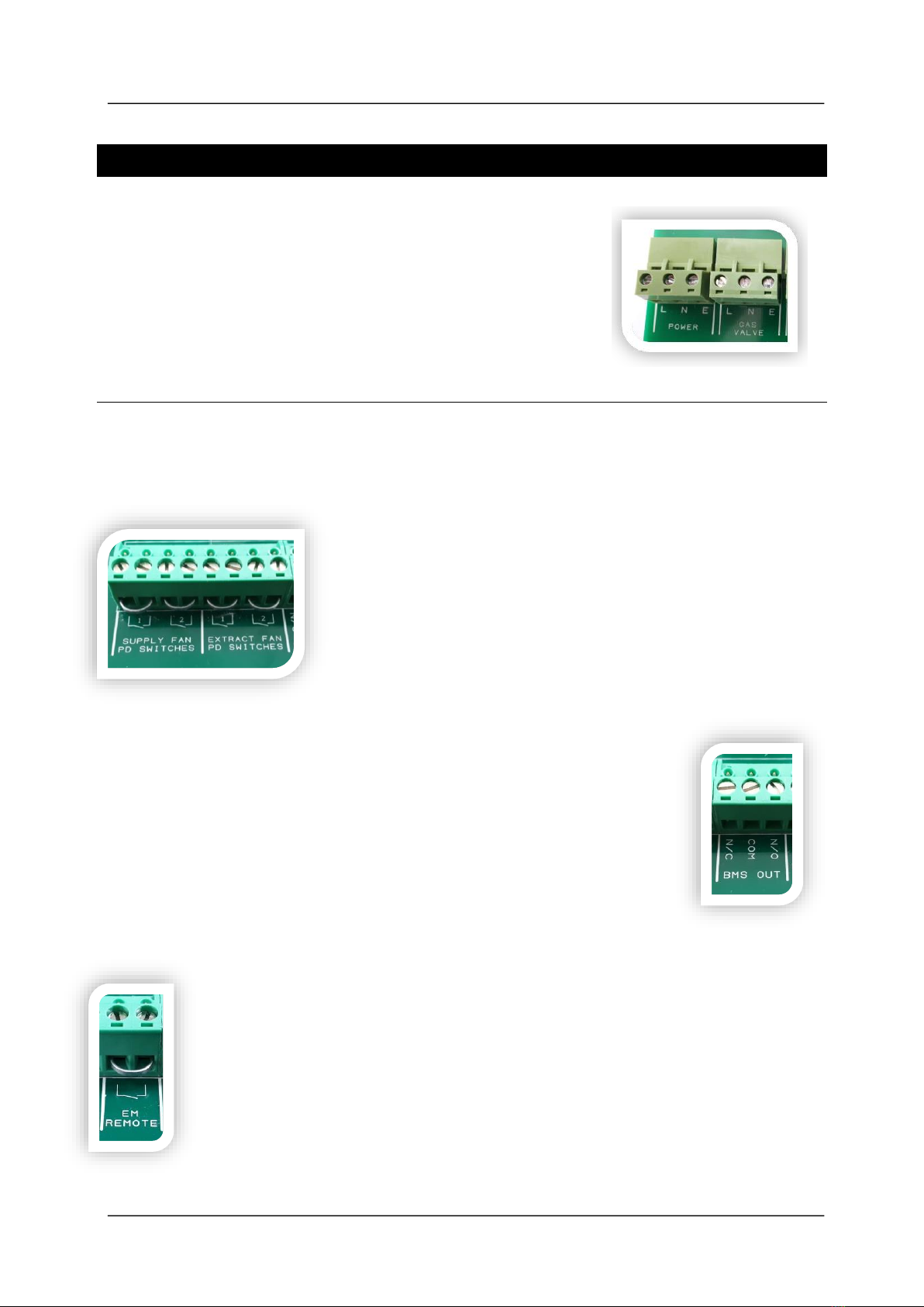
2.6 GAS DETECTOR
These connections can be wired to a Merlin gas detector (LPG,
natural gas or carbon monoxide) as shown.
If no detector is being used leave the link in between the “ ”.
Refer to your detector guide for more information.
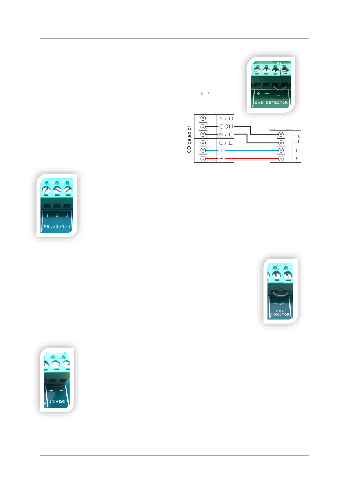
2.7 FS 1/2/3/4
This terminal switches when the key is turned on and off.
This can be linked to a fan switch (panel supplied separately) which can
provide power to the fans when the control panel is switched on.
2.8 CO2 MONITOR
This terminal can be wired to CO2 monitor to shut off the system in the
event of CO2 being at alarm level.
If no CO2 monitor is connected, the panel will ‘beep’ and CO2 LED will
flash 3 times to indicate this terminal has been disabled.
2.9 12V DC
This is a permanent 12v DC output when there is power at the panel and can
be used to create a relay switch with the BMS relay output.
This is normally used to power a PM2 current monitor. (Supplied separately)
Contact your supplier for more information.

Merlin 1500S User Guide
Rev: 07 05-19 6
3Installation & Operation
3.1 System ON and OFF
Turn the Fans On.
Turn the key switch to ON position.
To turn the system off, turn the key switch to OFF position.
3.2 Emergency Shut Off
The emergency shut off button is located on the front of the panel.
There is also a facility for remote shut off buttons to be wired in series on the circuit board.
The emergency shut off button(s) will cut off the gas supply when activated.
To reinstate the system, the emergency shut off button(s) will need to be reset and the panel
restarted.
3.3 BMS integration
The Merlin 1500S can be integrated with a BMS to make or break a circuit on
gas on/gas off, (valve open or valve closed). This will tell the BMS whether or not
power is being sent to the solenoid.
There is a dip-switch located on the inside facia of the Merlin 1500S labelled
[BMS SEL].
This is factory set in the OFF position which signals the BMS on gas on/gas off.
When switched to the ON position, the 1500S will only signal the BMS on a fault, i.e.
fan fault, CO2 high level detected, gas detected, EM Stop pressed, etc.
3.4 Fan Switch Integration
There is the facility to connect a Fan Switch (FS1 or FS2 sold separately).
The Fan Switch provides the facility to turn on the fan(s) when the key switch on the Merlin 1500S
is in the on position and turn the power off to the fan(s) when the key switch on the Merlin 1500S
is in the off position.
There is a dip-switch located inside the facia of the Merlin 1500S labelled [EM SEL].
This is factory set in the OFF position which instructs the system to shut down the fan(s) and gas
supply on activation of the Emergency shut off button(s).
On installation, this can be switched to the ON position if required. This will
instruct the system to leave the fans on and only shut off the gas supply on
activation of the Emergency shut off button(s).
Note: This option is not available if Fan Switch is not installed.
Merlin 1500S User Guide
Rev: 07 05-19 7
3.5 Fire alarm integration
The Merlin 1500S can be integrated with a fire alarm to close the gas supply automatically in the
event of a fire.
The volt free fire alarm signal can be wired in series with any remote emergency shut off buttons.
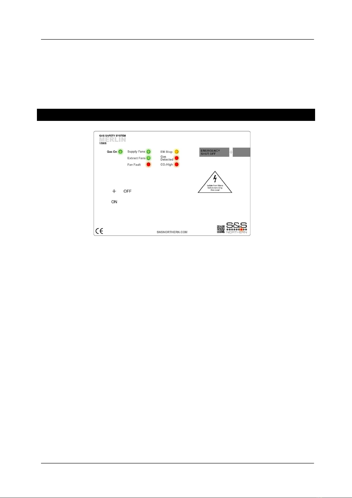
4Panel LED status
When the system is connected to the mains supply, the Red LED of the S&S Logo located in the
bottom right corner of the panel will illuminate. When no power is present, this LED will not
illuminate.
Gas On
When the fans are running at the correct speed and the key switch is turned on, the Merlin 1500S
will open the gas valve and the green ‘Gas On’ LED will illuminate.
ON = Gas On
OFF = Gas Off
Supply Fans
Under normal working the LED will illuminate GREEN. If a supply fan fault is detected, the LED will
be flashing. After 10 seconds of flashing, the gas supply will shut off.
ON = OK
FLASHING = One of the supply fans is not running.
Extract Fans
Under normal working the LED will illuminate GREEN. If an extract fan fault is detected, the LED
will be flashing. After 10 seconds of flashing, the gas supply will shut off.
ON = OK
FLASHING = One of the extract fans is not running

Merlin 1500S User Guide
Rev: 07 05-19 8
Fan Fault
Under normal working conditions this LED is off. If a fan fault is present for more than 10 seconds,
the LED will illuminate RED.
OFF = OK
ON = the gas supply has been shut off due to a ventilation fault.
IF A FAULT IS FOUND YOU WILL NEED TO CONTACT YOUR SERVICE/MAINTENANCE COMPANY.
YOU SHOULD NOT ATTEMPT TO CARRY OUT A REPAIR UNLESS YOU ARE QUALIFIED TO DO SO.
EM Stop
If an emergency shut off button (either remote or on the panel) is pressed, the LED will illuminate
AMBER and the gas turned off. The EM Stop button must be re-set before restarting the system.
OFF = OK
ON = EM Stop button pressed
Gas Detected
Under normal working conditions this LED is off. If the external Merlin detector connected detects
gas this will show RED and the Gas valve will turn off.
OFF = OK
ON = Gas detected.
CO2High
Under normal working conditions this LED is off. If the concentration of CO2 in the air is at
alarm level (relevant detector required), the LED will show RED and the Gas valve will turn off.
OFF = OK
ON = the concentration of CO2 is at alarm level.
5Maintenance
To keep your panel in good working order, you must follow these steps:
DO carefully remove any accumulated dust from the outer enclosure once a month.
NEVER use detergents or solvents to clean your device –this may permenantly or temporarily
damage the panel
NEVER spray air fresheners, hair spray, paint or other aerosols near the device.
NEVER paint the device. Paint will seal vents and interfere with the device.

Merlin 1500S User Guide
Rev: 07 05-19 9
61500S Wiring Spec
1. POWER: Mains Input 110-240VAC. Single phase
2. GAS VALVE: Gas Solenoid Valve Power Output, 110-240VAC. Max 3A
3. ELECTRIC CONTACTOR: Disabled
4. WATER VALVE: Disabled
5. SUPPLY FAN 1 external pressure differential switch or current switch. VOLT FREE INPUT
6. SUPPLY FAN 2 external pressure differential switch or current switch. VOLT FREE INPUT
7. EXTRACT FAN 1 external pressure differential switch or current switch. VOLT FREE INPUT
8. EXTRACT FAN 2 external pressure differential switch or current switch. VOLT FREE INPUT
9. BMS OUT contacts. Normally Closed, Common and Normally Open.
10. PRESSURE SENSOR: Disabled
11. EM REMOTE: Remote EM Stop buttons and Fire Alarm input wired in series (purchased separately).
VOLT FREE INPUT
12. GAS DETECTOR: power supply and VOLT FREE INPUT (purchased separately).
13. FS1/2/3/4: Fan Switch output (purchased separately).
For wiring instruction see Fan Switch user manual.
14. CO2 MONITOR: (purchased separately). VOLT FREE INPUT
15. 12VDC: Permanent 12VDC output (Normally used to power a PM2 Current Monitor). 50A Max.
1
2
5 6 7 8
9
10
11
12
13
14
15
L
N
E
PD Switches or Current Switches
(Volt Free)
Gas Valve
EM
Stop
CO2
Monitor
Gas
Detector
PM2
3
4

Merlin 1500S User Guide
Rev: 07 05-19 10

Merlin 1500S User Guide
Rev: 07 05-19 11
Merlin 1500S User Guide
Rev: 07 05-19 12
7Manufacturer’s Warranty
3 Year Limited Warranty
Warranty coverage: The manufacturer warrants to the original consumer purchaser, that this product will be free of
defects in material and workmanship for a period of three (3) years from date of purchase. The manufacturer’s liability
hereunder is limited to replacement of the product with repaired product at the discretion of the manufacture. This
warranty is void if the product has been damaged by accident, unreasonable use, neglect, tampering or other causes
not arising from defects in material or workmanship. This warranty extends to the original consumer purchaser of the
product only.
Warranty disclaimers: Any implied warranties arising out of this sale, including but not limited to the implied warranties of
description, merchantability and intended operational purpose, are limited in duration to the above warranty period. In
no event shall the manufacturer be liable for loss of use of this product or for any indirect, special, incidental or
consequential damages, or costs, or expenses incurred by the consumer or any other user of this product, whether due to
a breach of contract, negligence, strict liability in tort or otherwise. The manufacturer shall have no liability for any personal
injury, property damage or any special, incidental, contingent or consequential damage of any kind resulting from gas
leakage, fire or explosion. This warranty does not affect your statutory rights.
Warranty Performance: During the above warranty period, your product will be replaced with a comparable product if
the defective product is returned together with proof of purchase date. The replacement product will be in warranty for
the remainder of the original warranty period or for six months –whichever is the greatest.
CONTACT US:
S&S Northern Head Office
Tel: +44(0) 1257 470 983
Fax: +44(0) 1257 471 937
www.snsnorthern.com
info@snsnorthern.com
South East Division
Tel: +44(0) 1702 291 725
Fax: +44(0) 1702 299 148
south@snsnorthern.com
S&S Northern is the owner of this document and reserves all rights of modification without prior notice.
Table of contents


