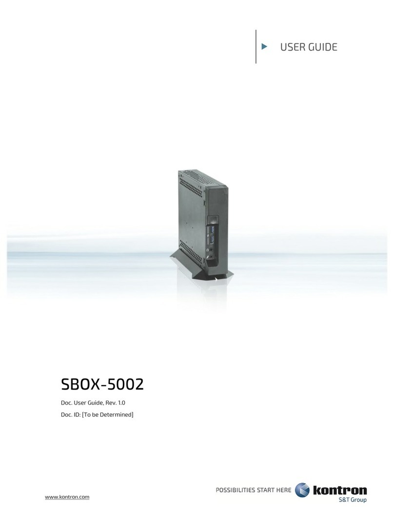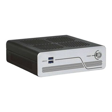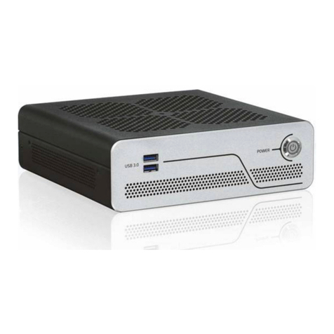
SBOX-5210 - User Guide, Rev. 1.0
www.kontron.com // 11
12.2.7. Save & Exit Setup Menu....................................................................................................................................................................86
Appendix A: List of Acronyms.....................................................................................................................................................................87
About Kontron ..................................................................................................................................................................................................88
List of Tables
Table 1: Power LED Status.............................................................................................................................................................................21
Table 2: Technical Specifications...............................................................................................................................................................47
Table 3: Mechanical Specifications ...........................................................................................................................................................48
Table 4: Environmental Conditions ...........................................................................................................................................................49
Table 5: Standards and Certifications ......................................................................................................................................................49
Table 6: DC Power Input (see Figure 2, pos. 1)....................................................................................................................................... 50
Table 7: Ethernet Connector (see Figure 2, pos. 4) ..............................................................................................................................50
Table 8: USB 3.1 Port -- Type C (see Figure 1, pos. 5).............................................................................................................................51
Table 9: USB 3.1 Port -- Type A (see Figure 1, pos. 4 & Figure 2, pos. 5) .......................................................................................... 51
Table 10: USB 2.0 Port (Figure 2, pos. 6) .................................................................................................................................................. 52
Table 11: DP Connector (see Figure 2, pos. 2)......................................................................................................................................... 52
Table 12: HDMI Connector (see Figure 2, pos. 3)................................................................................................................................... 53
Table 13: Line-Out Connector (see Figure 1, pos. 2) ............................................................................................................................. 53
Table 14: Mic-In Connector (see Figure 1, pos. 3).................................................................................................................................. 53
Table 15: Hotkeys Table.................................................................................................................................................................................54
Table 16: Main Setup Menu Sub-Screens and Functions ................................................................................................................... 55
Table 17: List of Acronyms............................................................................................................................................................................87
List of Figures
Figure 1: Front I/O Panel.................................................................................................................................................................................21
Figure 2: Rear I/O Panel.................................................................................................................................................................................23
Figure 3: Ethernet LED Status......................................................................................................................................................................24
Figure 4: Right-side I/O Panel..................................................................................................................................................................... 25
Figure 5: Internal View -- Top Side (without cover).............................................................................................................................. 26
Figure 6: Descrewing the rear access cover of the SBOX-5210.......................................................................................................29
Figure 7: Pulling down the rear access cover and sliding backward the top access cover.................................................... 29
Figure 8: Descrewing the hard disk tray..................................................................................................................................................30
Figure 9: Rubber feet......................................................................................................................................................................................36
Figure 10: Securing the rubber feet to the chassis...............................................................................................................................36
Figure 11: Chassis desk stand....................................................................................................................................................................... 37
Figure 12: Securing the chassis desk stand to the chassis................................................................................................................ 37
Figure 13: Wall mount kit...............................................................................................................................................................................38
Figure 14: Hole pattern of wall mount kit for SBOX-5210..................................................................................................................38
Figure 15: Aligning the holes of wall mount brackets and chassis................................................................................................. 39
Figure 16: Optional VESA mounting kit .....................................................................................................................................................40
Figure 17: Hole pattern of VESA adapter..................................................................................................................................................40
Figure 18: Securing the thumb screws ......................................................................................................................................................41
Figure 19: Securing the VESA adapter onto the SBOX-5210 ...............................................................................................................41
Figure 20: Hanging the SBOX-5210 on the mounting surface ..........................................................................................................42
Figure 21: Mechanical Drawing...................................................................................................................................................................48
Figure 22: BIOS Main Menu Screen System Data and Time .............................................................................................................. 56
Figure 23: BIOS Main Menu Screen -- System Information.................................................................................................................57
Figure 24: BIOS Main Menu Screen -- System Information................................................................................................................58
Figure 25: BIOS Advanced Menu.................................................................................................................................................................60
Figure 26: BIOS Advanced Menu -- Onboard Devices Configuration................................................................................................61
Figure 27: BIOS Advanced Menu -- Auto BIOS Update..........................................................................................................................62
Figure 28: BIOS Advanced Menu -- CPU Configuration........................................................................................................................ 63
Figure 29: BIOS Advanced Menu -- Drive Configuration......................................................................................................................64


