S&T Kontron pITX-iMX8M User manual
USER GUIDE
pITX-iMX8M
User Guide Rev. 1.4
Doc-ID: 1064-7940

pITX-iMX8M – User Guide Rev. 1.4
This page has been intentionally left blank

pITX-iMX8M – User Guide Rev. 1.4
www.kontron.com // 3
PITX
-IMX8M – USER GUIDE
Disclaimer
Kontron would like to point out that the information contained in this manual may be subject to alteration, particularly
as a result of the constant upgrading of Kontron products. This document does not entail any guarantee on the part
of Kontron with respect to technical processes described in the manual or any product characteristics set out in the
manual. Kontron assumes no responsibility or liability for the use of the described product(s), conveys no license or
title under any patent, copyright or mask work rights to these products and makes no representations or warranties
that these products are free from patent, copyright or mask work right infringement unless otherwise specified.
Applications that are described in this manual are for illustration purposes only. Kontron makes no representation or
warranty that such application will be suitable for the specified use without further testing or modification. Kontron
expressly informs the user that this manual only contains a general description of processes and instructions which
may not be applicable in every individual case. In cases of doubt, please contact Kontron.
This manual is protected by copyright. All rights are reserved by Kontron. No part of this document may be reproduced,
transmitted, transcribed, stored in a retrieval system, or translated into any language or computer language, in any
form or by any means (electronic, mechanical, photocopying, recording, or otherwise), without the express written
permission of Kontron. Kontron points out that the information contained in this manual is constantly being updated
in line with the technical alterations and improvements made by Kontron to the products and thus this manual only
reflects the technical status of the products by Kontron at the time of publishing.
Brand and product names are trademarks or registered trademarks of their respective owners.
©2021 by Kontron Europe GmbH
Kontron Europe GmbH
Gutenbergstraße 2
85737 Ismaning, Germany
www.kontron.com
pITX-iMX8M – User Guide Rev. 1.4
www.kontron.com // 4
Intended Use
THIS DEVICE AND ASSOCIATED SOFTWARE ARE NOT DESIGNED, MANUFACTURED OR INTENDED FOR USE OR RESALE
FOR THE OPERATION OF NUCLEAR FACILITIES, THE NAVIGATION, CONTROL OR COMMUNICATION SYSTEMS FOR
AIRCRAFT OR OTHER TRANSPORTATION, AIR TRAFFIC CONTROL, LIFE SUPPORT OR LIFE SUSTAINING APPLICATIONS,
WEAPONS SYSTEMS, OR ANY OTHER APPLICATION IN A HAZARDOUS ENVIRONMENT, OR REQUIRING FAIL-SAFE
PERFORMANCE, OR IN WHICH THE FAILURE OF PRODUCTS COULD LEAD DIRECTLY TO DEATH, PERSONAL INJURY, OR
SEVERE PHYSICAL OR ENVIRONMENTAL DAMAGE (COLLECTIVELY, "HIGH RISK APPLICATIONS").
You understand and agree that your use of Kontron devices as a component in High Risk Applications is entirely at
your risk. To minimize the risks associated with your products and applications, you should provide adequate design
and operating safeguards. You are solely responsible for compliance with all legal, regulatory, safety, and security
related requirements concerning your products. You are responsible to ensure that your systems (and any Kontron
hardware or software components incorporated in your systems) meet all applicable requirements. Unless
otherwise stated in the product documentation, the Kontron device is not provided with error-tolerance capabilities
and cannot therefore be deemed as being engineered, manufactured or setup to be compliant for implementation or
for resale as device in High Risk Applications. All application and safety related information in this document
(including application descriptions, suggested safety measures, suggested Kontron products, and other materials) is
provided for reference only.
Handling and operation of the product is permitted only for trained personnel within a work
place that is access controlled. Please follow the “General Safety Instructions” supplied with
the system.
You find the most recent version of the “General Safety Instructions“ online in the download
area of this product.

pITX-iMX8M – User Guide Rev. 1.4
www.kontron.com // 5
Revision History
Revision Brief Description of Changes Date of Issue Author
1.0 Initial Issue 2021-February-17 hjs
1.1 Jumper J29 and J18 in Figure 4: Front Side corrected 2021-February-22 hjs
1.2 Word2016 issues 2021-March-25 hjs
1.3 Internal audio header (J9) in chapter 6.18 added, new Table 8: Switch
SW1 and Table 9: Switch SW2Switch SW1/2
2021-July-05 hjs
1.4 LVDS updates in Table 4 and Table 7 2021-July-20 hjs
Terms and Conditions
Kontron warrants products in accordance with defined regional warranty periods. For more information about
warranty compliance and conformity, and the warranty period in your region, visit http://www.kontron.com/terms-
and-conditions.
Kontron sells products worldwide and declares regional General Terms & Conditions of Sale, and Purchase Order
Terms & Conditions. Visit http://www.kontron.com/terms-and-conditions.
For contact information, refer to the corporate offices contact information on the last page of this user guide or visit
our website CONTACT US.
Customer Support
Find Kontron contacts by visiting: https://www.kontron.de/support-and-services.
Customer Service
As a trusted technology innovator and global solutions provider, Kontron extends its embedded market strengths into
a services portfolio allowing companies to break the barriers of traditional product lifecycles. Proven product
expertise coupled with collaborative and highly-experienced support enables Kontron to provide exceptional peace
of mind to build and maintain successful products.
For more details on Kontron’s service offerings such as: enhanced repair services, extended warranty, Kontron
training academy, and more visit http://www.kontron.com/support-and-services/services.
Customer Comments
If you have any difficulties using this user guide, discover an error, or just want to provide some feedback, contact
Kontron support. Detail any errors you find. We will correct the errors or problems as soon as possible and post the
revised user guide on our website.

pITX-iMX8M – User Guide Rev. 1.4
www.kontron.com // 6
Symbols
The following symbols may be used in this manual
DANGER indicates a hazardous situation which, if not avoided,
will result in death or serious injury.
WARNING indicates a hazardous situation which, if not avoided,
could result in death or serious injury.
NOTICE indicates a property damage message.
CAUTION indicates a hazardous situation which, if not avoided,
may result in minor or moderate injury.
Electric Shock!
This symbol and title warn of hazards due to electrical shocks (> 60
V) when touching
products or parts of products. Failure to observe the precautions indicated and/or prescribed
by the law may endanger your life/health and/or result in damage to your material.
ESD Sensitive Device!
This symbol and title inform that the electronic boards and their components are sensitive to
static electricity. Care must therefore be taken during all handling operations and inspections
of this product in order to ensure product integrity at all times.
HOT Surface!
Do NOT touch! Allow to cool before servicing.
Laser!
This symbol inform of the risk of exposure to laser beam and light emitting devices (LEDs)
from an electrical device. Eye protection per manufacturer notice shall review before
servicing.
This symbol indicates general information about the product and the user guide.
This symbol also indicates detail information about the specific product configuration.
This symbol precedes helpful hints and tips for daily use.
pITX-iMX8M – User Guide Rev. 1.4
www.kontron.com // 7
For Your Safety
Your new Kontron product was developed and tested carefully to provide all features necessary to ensure its
compliance with electrical safety requirements. It was also designed for a long fault-free life. However, the life
expectancy of your product can be drastically reduced by improper treatment during unpacking and installation.
Therefore, in the interest of your own safety and of the correct operation of your new Kontron product, you are
requested to conform with the following guidelines.
High Voltage Safety Instructions
As a precaution and in case of danger, the power connector must be easily accessible. The power connector is the
product’s main disconnect device.
Warning
All operations on this product must be carried out by sufficiently skilled personnel only.
Electric Shock!
Before installing a non hot-swappable Kontron product into a system always ensure that
your mains power is switched off. This also applies to the installation of piggybacks. Serious
electrical shock hazards can exist during all installation, repair, and maintenance operations
on this product. Therefore, always unplug the power cable and any other cables which
provide external voltages before performing any work on this product.
Earth ground connection to vehicle’s chassis or a central grounding point shall remain
connected. The earth ground cable shall be the last cable to be disconnected or the first
cable to be connected when performing installation or removal procedures on this product.
Special Handling and Unpacking Instruction
ESD Sensitive Device!
Electronic boards and their components are sensitive to static electricity. Therefore, care
must be taken during all handling operations and inspections of this product, in order to
ensure product integrity at all times.
Do not handle this product out of its protective enclosure while it is not used for operational purposes unless it is
otherwise protected.
Whenever possible, unpack or pack this product only at EOS/ESD safe work stations. Where a safe work station is
not guaranteed, it is important for the user to be electrically discharged before touching the product with his/her
hands or tools. This is most easily done by touching a metal part of your system housing.
It is particularly important to observe standard anti-static precautions when changing piggybacks, ROM devices,
jumper settings etc. If the product contains batteries for RTC or memory backup, ensure that the product is not
placed on conductive surfaces, including anti-static plastics or sponges. They can cause short circuits and damage
the batteries or conductive circuits on the product.

pITX-iMX8M – User Guide Rev. 1.4
www.kontron.com // 8
Lithium Battery Precautions
If your product is equipped with a lithium battery, take the following precautions when replacing the battery.
Danger of explosion if the battery is replaced incorrectly.
Replace only with same or equivalent battery type recommended by the manufacturer.
Dispose of used batteries according to the manufacturer’s instructions.
General Instructions on Usage
In order to maintain Kontron’s product warranty, this product must not be altered or modified in any way. Changes
or modifications to the product, that are not explicitly approved by Kontron and described in this user guide or
received from Kontron Support as a special handling instruction, will void your warranty.
This product should only be installed in or connected to systems that fulfill all necessary technical and specific
environmental requirements. This also applies to the operational temperature range of the specific board version
that must not be exceeded. If batteries are present, their temperature restrictions must be taken into account.
In performing all necessary installation and application operations, only follow the instructions supplied by the
present user guide.
Keep all the original packaging material for future storage or warranty shipments. If it is necessary to store or ship
the product then re-pack it in the same manner as it was delivered.
Special care is necessary when handling or unpacking the product. See Special Handling and Unpacking Instruction.
Quality and Environmental Management
Kontron aims to deliver reliable high-end products designed and built for quality, and aims to complying with
environmental laws, regulations, and other environmentally oriented requirements. For more information regarding
Kontron’s quality and environmental responsibilities, visit http://www.kontron.com/about-kontron/corporate-
responsibility/quality-management.
Disposal and Recycling
Kontron’s products are manufactured to satisfy environmental protection requirements where possible. Many of
the components used are capable of being recycled. Final disposal of this product after its service life must be
accomplished in accordance with applicable country, state, or local laws or regulations.
WEEE Compliance
The Waste Electrical and Electronic Equipment (WEEE) Directive aims to:
Reduce waste arising from electrical and electronic equipment (EEE)
Make producers of EEE responsible for the environmental impact of their products, especially when the product
become waste
Encourage separate collection and subsequent treatment, reuse, recovery, recycling and sound environmental
disposal of EEE
Improve the environmental performance of all those involved during the lifecycle of EEE
Environmental protection is a high priority with Kontron.
Kontron follows the WEEE directive
You are encouraged to return our products for proper disposal.

pITX-iMX8M – User Guide Rev. 1.4
www.kontron.com // 9
Table of Contents
Symbols........................................................................................................................................................................................................................6
For Your Safety..........................................................................................................................................................................................................7
High Voltage Safety Instructions .......................................................................................................................................................................7
Special Handling and Unpacking Instruction.................................................................................................................................................7
Lithium Battery Precautions............................................................................................................................................................................... 8
General Instructions on Usage........................................................................................................................................................................... 8
Quality and Environmental Management...................................................................................................................................................... 8
Disposal and Recycling ......................................................................................................................................................................................... 8
WEEE Compliance ................................................................................................................................................................................................... 8
Table of Contents.....................................................................................................................................................................................................9
List of Tables............................................................................................................................................................................................................10
List of Figures ...........................................................................................................................................................................................................11
1/ Introduction................................................................................................................................................................................................13
2/ Description .................................................................................................................................................................................................14
2.1. Configurations..................................................................................................................................................................................................15
2.2. Scope of Delivery............................................................................................................................................................................................16
3/ Installation procedure............................................................................................................................................................................17
3.1. Installing the Board........................................................................................................................................................................................ 17
3.2. Safety Requirements according IEC 62368..........................................................................................................................................18
3.3. Lithium battery precautions ......................................................................................................................................................................19
4/ System specifications ...........................................................................................................................................................................20
4.1. Component Main Data.................................................................................................................................................................................20
4.2. Environmental Conditions......................................................................................................................................................................... 22
4.3. Block Diagram ................................................................................................................................................................................................ 23
4.4. Power Consumption .................................................................................................................................................................................... 25
5/ Jumpers, Switches and Connectors.................................................................................................................................................26
5.1. Hardware Configuration Setting ..............................................................................................................................................................26
5.2. Mainboard Placement and I/O Locations............................................................................................................................................28
5.2.1. Interfaces Rear Side ...................................................................................................................................................................................31
5.3. Cooler Solutions............................................................................................................................................................................................. 32
5.3.1. Passive Cooler (1064-7069) ................................................................................................................................................................... 32
5.3.2. Active Cooler (1064-8396) ..................................................................................................................................................................... 32
6/ Hardware Specifications...................................................................................................................................................................... 33
6.1. Processor Support......................................................................................................................................................................................... 33
6.2. System Memory Support ...........................................................................................................................................................................34
6.3. MicroSD and MicroSIM (J12)...................................................................................................................................................................... 35
6.4. Ethernet Connectors (I/O area, J4) ........................................................................................................................................................36
6.4.1. ETH0 LEDs..................................................................................................................................................................................................... 37
6.4.2. ETH1 LEDs ..................................................................................................................................................................................................... 37
6.5. USB Connectors ............................................................................................................................................................................................. 37
6.5.1. USB Connectors (I/O area, J13).............................................................................................................................................................. 37
6.5.2. USB internal (J2).........................................................................................................................................................................................39
6.5.3. USB OTG (J28).............................................................................................................................................................................................. 39
6.6. Fan Connector (internal, J8)......................................................................................................................................................................40
6.7. DC Power Supply Connector Options ....................................................................................................................................................40
6.7.1. DC Power Jack Connector (12 Vin Ext., J15).........................................................................................................................................41
6.7.2. Internal Power Connector (Vin Int., J16) .............................................................................................................................................41

pITX-iMX8M – User Guide Rev. 1.4
www.kontron.com // 10
6.8. Pigtail Battery Header (J22) ......................................................................................................................................................................42
6.9. GPIO Connector (internal, J17) ..................................................................................................................................................................42
6.10. Jumper LVDS Panel Voltage (J18)..........................................................................................................................................................43
6.11. Jumper LVDS Backlight Voltage (J29)...................................................................................................................................................43
6.12. Switches..........................................................................................................................................................................................................44
6.12.1. Boot Select (SW1) .....................................................................................................................................................................................44
6.12.2. MicroSD Card Write Protection (SW2).............................................................................................................................................44
6.12.3. PCIE Spread Spectrum Clocking -0.5% (SW2: 2-3) .....................................................................................................................44
6.13. Buttons ............................................................................................................................................................................................................44
6.13.1. External ON-OFF Button (J24).............................................................................................................................................................44
6.13.2. External Reset (J23) ................................................................................................................................................................................45
6.14. LVDS (Industrial Variant, internal, J11).................................................................................................................................................45
6.15. HDMI connector (J7) ...................................................................................................................................................................................46
6.16. Mini Display Port (J14) ............................................................................................................................................................................... 47
6.17. SPDIF Internal Audio Header (J10).........................................................................................................................................................48
6.18. Internal audio (J9) .......................................................................................................................................................................................49
6.19. SPI/I2C3 (J26)................................................................................................................................................................................................49
6.20. M.2 Connector (B-Key) (J1)...................................................................................................................................................................... 50
6.21. Serial COM P1 (J25)...................................................................................................................................................................................... 52
6.22. Serial COM P2 (J3)....................................................................................................................................................................................... 52
6.23. Serial COM P3 (J19)..................................................................................................................................................................................... 53
6.24. Camera connector (J5, J6) ....................................................................................................................................................................... 53
6.25. Thermal Sensor (U24) .............................................................................................................................................................................. 56
7/ Bootloader Operation............................................................................................................................................................................ 57
7.1. Copyrights and Licensing of U-Boot....................................................................................................................................................... 57
7.2. Bootloader Quickstart ................................................................................................................................................................................. 57
7.3. Bootloader Commands ...............................................................................................................................................................................58
7.4. Kontron Bootloader Command Extensions ........................................................................................................................................ 59
7.4.1. kboardinfo - Kontron Board Information.......................................................................................................................................... 59
7.5. Bootloader Environment ............................................................................................................................................................................ 59
7.6. Bootloader Environment Update ............................................................................................................................................................60
7.7. Kontron Bootloader Environment Extensions ....................................................................................................................................61
7.8. Bootloader Mass Storage Support..........................................................................................................................................................61
7.8.1. QSPI flash .......................................................................................................................................................................................................61
7.8.2. SD Card and eMMC Devices...................................................................................................................................................................62
7.8.3. USB Storage Device................................................................................................................................................................................... 62
7.9. Bootloader File System Support .............................................................................................................................................................62
7.10. Bootloader Update......................................................................................................................................................................................62
8/ Technical Support................................................................................................................................................................................... 63
8.1. Warranty ...........................................................................................................................................................................................................63
8.2. Returning Defective Merchandise..........................................................................................................................................................63
About Kontron – Member of the S&T Group............................................................................................................................................... 65
List of Tables
Table 1: Component Main Data .........................................................................................................................................................................15
Table 2: Scope of Delivery pITX-iMX8M........................................................................................................................................................16
Table 3: Scope of pITX-iMX8M Kit ...................................................................................................................................................................16
Table 4: Component Main Data .......................................................................................................................................................................20

pITX-iMX8M – User Guide Rev. 1.4
www.kontron.com // 11
Table 5: Environmental Conditions ................................................................................................................................................................22
Table 6: Power Consumption............................................................................................................................................................................ 25
Table 7: Jumpers and Connectors................................................................................................................................................................... 26
Table 8: Switch SW1 ............................................................................................................................................................................................. 27
Table 9: Switch SW2............................................................................................................................................................................................. 27
Table 10: Processor Support ............................................................................................................................................................................. 33
Table 11: Pin Assignment MicroSIM Combo Socket.................................................................................................................................. 35
Table 12: Pin Assignment Dual Ethernet ......................................................................................................................................................36
Table 13: ETH0 LED Signal Description.......................................................................................................................................................... 37
Table 14: ETH1 LED Signal Description .......................................................................................................................................................... 37
Table 15: Pin Assignment Dual USB................................................................................................................................................................ 37
Table 16: Signal Description ..............................................................................................................................................................................38
Table 17: USB Internal Connection ..................................................................................................................................................................39
Table 18: USB OTG Connection .........................................................................................................................................................................39
Table 19: Fan Header Mapping .........................................................................................................................................................................40
Table 20: Signal Description .............................................................................................................................................................................40
Table 21: Power Jack Connector........................................................................................................................................................................41
Table 22: Internal Power Connector ...............................................................................................................................................................41
Table 23: Pin Assignment...................................................................................................................................................................................42
Table 24: GPIO Connector...................................................................................................................................................................................42
Table 25: LVDS Panel Voltage...........................................................................................................................................................................43
Table 26: LVDS Panel Voltage...........................................................................................................................................................................43
Table 27: Boot Select Switch (SW1)................................................................................................................................................................44
Table 28: MicroSD Card Write Protection Switch .....................................................................................................................................44
Table 29: PCIE Spread Spectrum Clocking -0.5% Switch .......................................................................................................................44
Table 30: External ON-OFF Button .................................................................................................................................................................44
Table 31: External Reset Button.......................................................................................................................................................................45
Table 32: LVDS Pin Assignment .......................................................................................................................................................................45
Table 33: HDMI Mapping.....................................................................................................................................................................................46
Table 34: Mini Display Port................................................................................................................................................................................47
Table 35: Pin Assignment...................................................................................................................................................................................48
Table 36: Pin Assignment...................................................................................................................................................................................49
Table 37: SPI/I2C Pin Assignment ...................................................................................................................................................................49
Table 38: Pin Assignment...................................................................................................................................................................................50
Table 39: Pin Assignment................................................................................................................................................................................... 52
Table 40: Pin Assignment .................................................................................................................................................................................. 52
Table 41: Pin Assignment (assembly option) ............................................................................................................................................. 53
Table 42: Pin Assignment RS232 only........................................................................................................................................................... 53
Table 43: Pin Assignment (J5) .......................................................................................................................................................................... 53
Table 44: Pin Assignment (J6).......................................................................................................................................................................... 55
Table 45: Bootloader Command Extensions .............................................................................................................................................. 59
Table 46: Standard Environment Variables................................................................................................................................................60
Table 47: Bootloader Environment Extensions..........................................................................................................................................61
List of Figures
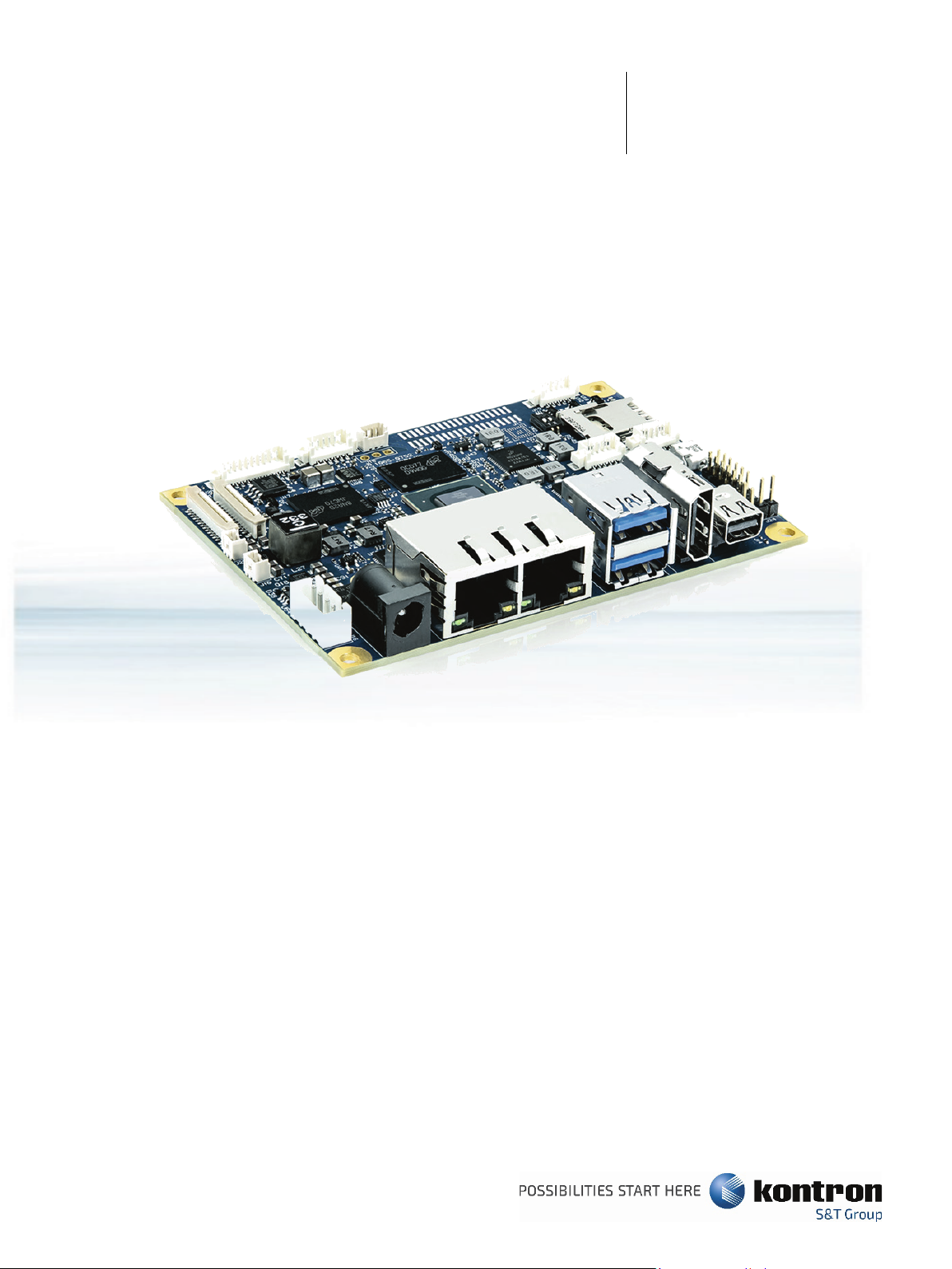
Figure 1: pITX-iMX8M Board...............................................................................................................................................................................16
Figure 2: Power Jack (left) and Internal Connector(right)......................................................................................................................18
Figure 3: Block Diagram ...................................................................................................................................................................................... 23
Figure 4: Front Side...............................................................................................................................................................................................28
Figure 5: Interfaces ............................................................................................................................................................................................... 29
Figure 6: Front View Jumpers/Switches ......................................................................................................................................................30
Figure 7: Interfaces Rear Side............................................................................................................................................................................31
Figure 8: Passive Cooler...................................................................................................................................................................................... 32
Figure 9: Active Cooler......................................................................................................................................................................................... 32
Figure 10: Block Diagram i.MX8M processor (Source: NXP).................................................................................................................34

pITX-iMX8M – User Guide Rev. 1.4
www.kontron.com // 12
Figure 11: Combo Connector for MicroSD and MicroSIM........................................................................................................................ 35
Figure 12: Ethernet Connector RJ-45 Jack with Integrated Magnetic ...............................................................................................36
Figure 13: USB 2.0/3.0 socket ........................................................................................................................................................................... 37
Figure 14: USB Internal Connector ..................................................................................................................................................................39
Figure 15: USB OTG Connector.......................................................................................................................................................................... 39
Figure 16: 3-pin Fan Connector ........................................................................................................................................................................40
Figure 17: Power Jack Connector ......................................................................................................................................................................41
Figure 18: Internal Power Connector ..............................................................................................................................................................41
Figure 19: Pigtail Battery Header.....................................................................................................................................................................42
Figure 20: GPIO Connector .................................................................................................................................................................................42
Figure 21: LVDS Panel Voltage..........................................................................................................................................................................43
Figure 22: LVDS Backlight Voltage Select Jumper ....................................................................................................................................43
Figure 23: LVDS Connector (optional) ...........................................................................................................................................................45
Figure 24: 19-pin HDMI connector ..................................................................................................................................................................46
Figure 25: Mini Display Port...............................................................................................................................................................................47
Figure 26: SPDIF Internal Header with 3 pins .............................................................................................................................................48
Figure 27: Internal Audio Header with 6 pins..............................................................................................................................................49
Figure 28: M.2 Connector (B-Key)................................................................................................................................................................... 50
Figure 29: Serial Wafer Socket COM P1......................................................................................................................................................... 52
Figure 30: Serial Wafer Socket COM P2 ........................................................................................................................................................ 52
Figure 31: Serial Wafer Socket COM P3 ......................................................................................................................................................... 53
Figure 32: 24-pin Camera CSI Connector ..................................................................................................................................................... 53
Figure 33: Sensor Location (red circle) ......................................................................................................................................................... 56
Figure 34: U-Boot Start Screen ........................................................................................................................................................................58
Figure 35: Kboardinfo........................................................................................................................................................................................... 59

pITX-iMX8M – User Guide Rev. 1.4
www.kontron.com // 13
1/ Introduction
This manual describes the pico-ITX board with five processors from NXP: i.MX8M QuadLite with 1.5 GHz, i.MX8M
Dual with 1.3 GHz and 1.5 GHz, i.MX8M Quad with 1.3 GHz and 1.5 GHz. This board will also be denoted pITX-iMX8M
within this Users Guide.
The use of this Users Guide implies a basic knowledge of PC hard- and software. This manual is focussed on
describing the pITX-iMX8M board’s special features and is not intended to be a standard PC textbook.
New users are recommended to study the short installation procedure stated in the following chapter before
switching-on the power.
All configuration and setup of the CPU board is either done automatically or manually by the user via the U-Boot
setup menus.
Latest revision of this manual, datasheet, U-Boot scripts, drivers, BSPs (Board Support Packages) can be
downloaded from Kontron Web Page.

pITX-iMX8M – User Guide Rev. 1.4
www.kontron.com // 14
2/ Description
The board is based on the NXP´s i.MX8M processor with either dual or quad core ARM. It is mechanically compliant
to the Pico-ITX (pITX) specification. Board key features are:
32-bit LPDDR4 3200 MT/s memory (up to 4 GB),
eMMC v5.1 storage (Up to 128 GB MLC/64 GB pseudoSLC),
Support graphic interfaces of 1x mini DP, 1x Internal Dual Channel LVDS Header, 1x HDMI, 2x Internal MIPI-
CSI (2 lanes each) headers,
1x M.2 B-Key half-size connector with PCIe, USB 3.0/2.0 and micro SIM interface,
1x Dual-Stacked USB 3.0 Rear Port,
1x USB OTG microUSB Type AB socket
1x USB 2.0 via Internal Header
2x 10/100/1000 Gigabit Ethernet Rear Port
1x 4-wire RS-232 Serial Port via Internal Header
2x 2-wire RS-232/UART Serial Port via Internal Header
1x Internal Front Panel Header for Line-In/Out and Microphone
1x SPDIF Internal Header
TPM 2.0
1x Internal Header for up to 8x configurable GPIOs
1x 12 V Fan Connector
Temperature Sensor
+12 V DC Input via locking barrel-type connector or internal power header
pITX form factor and cooling solution
Built with these functions, pITX-iMX8M Mother Board is ideal for ATM, Automation, Kiosk applications, medical
equipment, industrial automation, financial automation, process control, semiconductor equipment and network
security markets.
pITX-iMX8M – User Guide Rev. 1.4
www.kontron.com // 15
2.1. Configurations
Kontron offers the pITX-iMX8M in five different configurations.
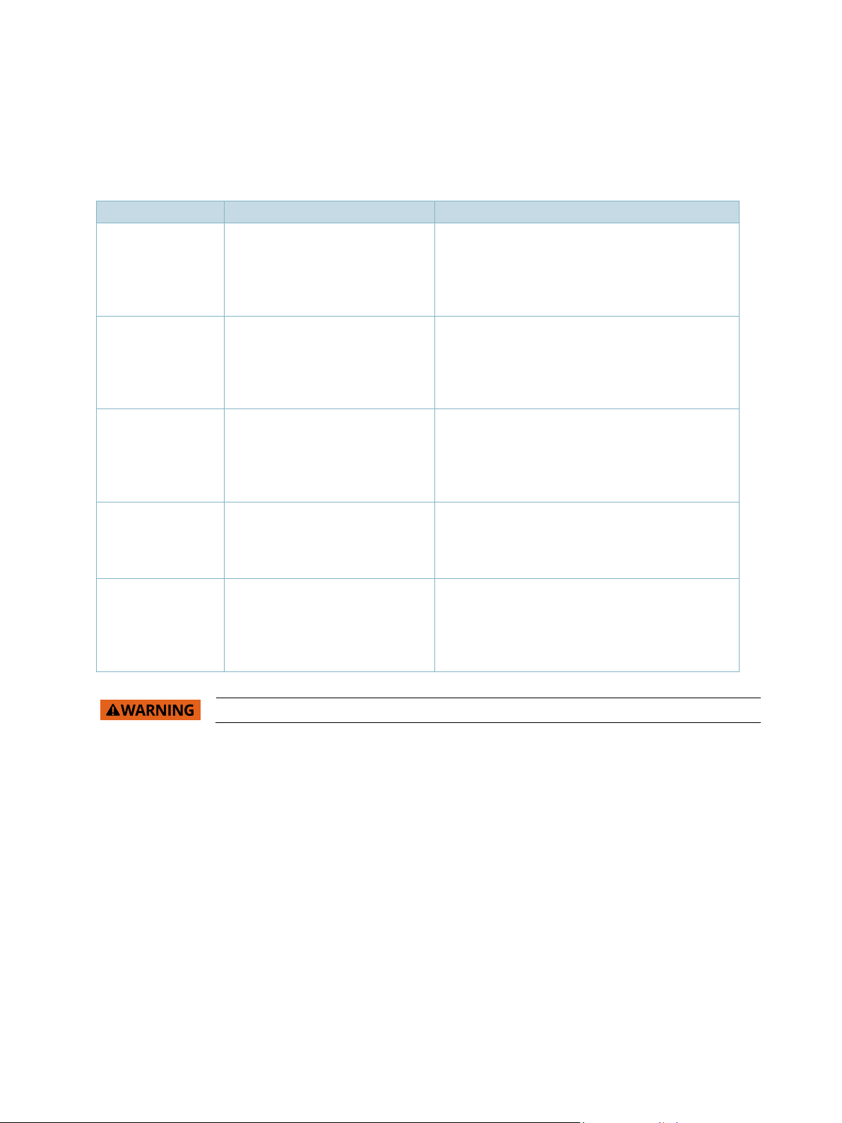
Table 1: Component Main Data
Product Number Article Description
44011-0208-13-2
pITX-iMX8M
Dual Core Industrial
pITX- iMX8M with
NXP i.MX8 M Dual Core Cortex®-A53 1.3 GHz with
GPU, VPU and HDR10 encoding, industrial
temperature range, 2 GByte LPDDR4, 8 GByte
eMMC (pSLC), HDMI and LVDS
44011-0408-13-4
pITX-iMX8M
Quad Core Industrial
pITX- iMX8M with
NXP i.MX8 M Quad Core Cortex®-A53 1.3GHz with
GPU, VPU and HDR10 encoding, industrial
temperature range, 4 GByte LPDDR4, 8 GByte
eMMC (pSLC), HDMI and LVDS
44011-0216-15-2 pITX-iMX8M
Dual Core Commercial
pITX- iMX8M with
NXP i.MX8 M Dual Core Cortex®-A53 1.5 GHz with
GPU, VPU and HDR10 encoding, commercial
temperature range, 2 GByte LPDDR4, 16 GByte
eMMC (MLC), HDMI and mDP
44011-0416-15-4lit pITX-iMX8M
Quad Lite Commercial
pITX- iMX8M with
NXP i.MX8 M Quad Core Cortex®-A53 1.5 GHz with
GPU, commercial temperature range, 4 GByte
LPDDR4, 16 GByte eMMC (MLC), HDMI and mDP
44011-0416-15-4 pITX-iMX8M
Quad Core Commercial
pITX- iMX8M with
NXP i.MX8 M Quad Core Cortex®-A53 1.5 GHz with
GPU, VPU and HDR10 encoding, commercial
temperature range, 4 GByte LPDDR4, 16 GByte
eMMC (MLC), HDMI and mDP.
Warning: Please do not operate the pITX-IMX8M without sufficient cooling system.
pITX-iMX8M – User Guide Rev. 1.4
www.kontron.com // 16
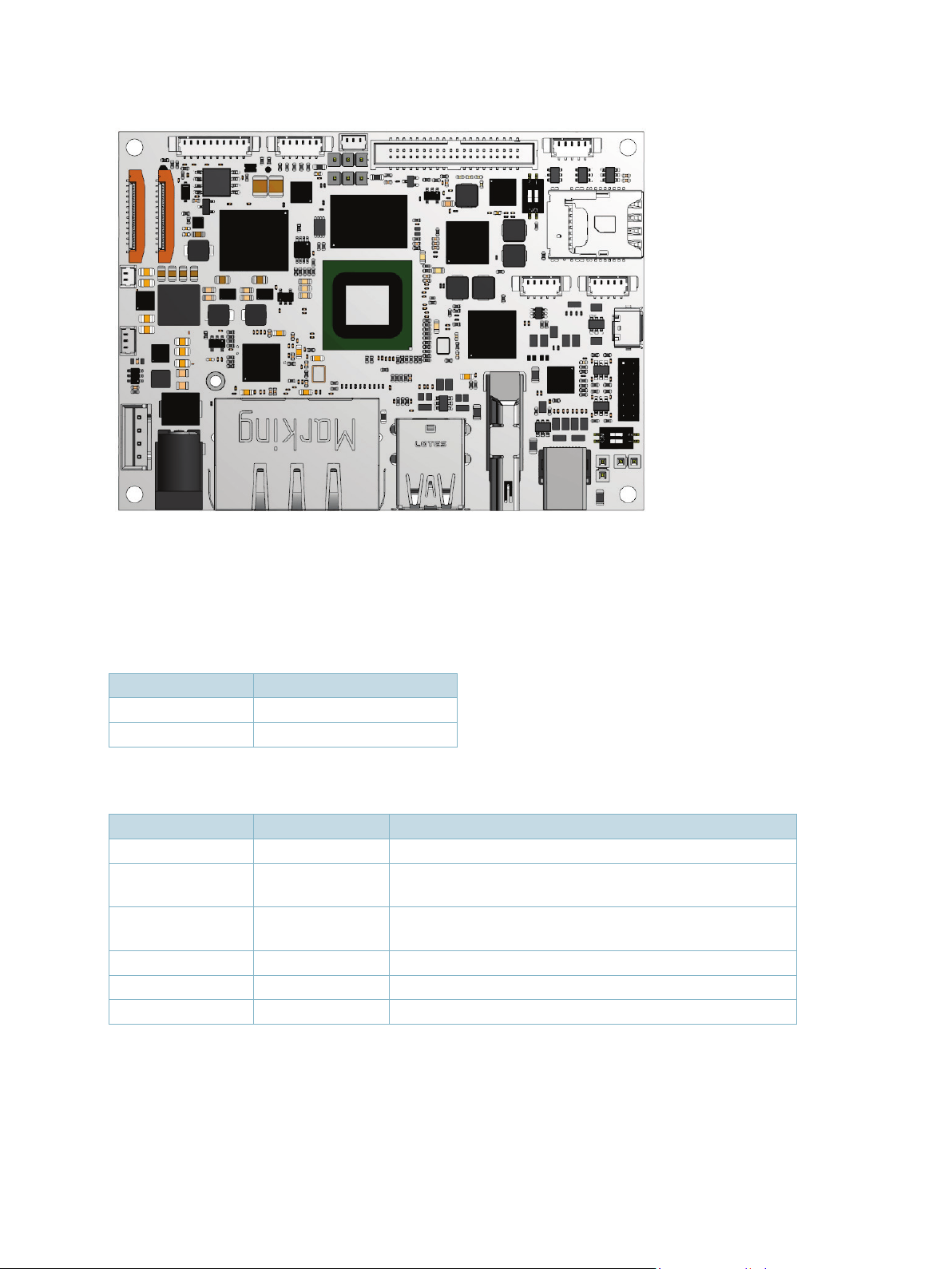
Figure 1: pITX-iMX8M Board
2.2. Scope of Delivery
Table 2: Scope of Delivery pITX-iMX8M
Part Description
Module pITX-iMX8M
Miscellaneous Quick Installation Guide
Table 3: Scope of pITX-iMX8M Kit
Part Part No. Description
Module pITX-iMX8M
Power Supply 1067-1755 12 V Power Supply: SCM PSU AC/DC 60 W 12 V KYCON (0-
40°C)
Cooling 1064-7069 Passive Cooler: heatsink with adhesive tape Fischer ICK S
25 X 25 X 12,5 + WLFT404
Cooling 1064-8396 Active Cooler
Software Linux-Image
Miscellaneous Foam Package, Quick Installation Guide

pITX-iMX8M – User Guide Rev. 1.4
www.kontron.com // 17
3/ Installation procedure
3.1. Installing the Board
ESD Sensitive Device!
Electrostatic discharge (ESD) can damage equipment and impair electrical circuitry.
•Wear ESD-protective clothing and shoes
•Wear an ESD-preventive wrist strap attached to a good earth ground
•Check the resistance value of the wrist strap periodically (OK: 1 MΩto 10 MΩ)
•Transport and store the board in its antistatic bag
•Handle the board at an approved ESD workstation
•Handle the board only by the edges
To get the board running follow these steps. If the board shipped from Kontron has already components like RAM
and CPU cooler mounted, then relevant steps below can be skipped.
1. Turn off the PSU (Power Supply Unit)
Turn off PSU (Power Supply Unit) completely (no mains power connected to the PSU) or
leave the Power Connectors unconnected while configuring the board. Otherwise
components (RAM, LAN cards etc.) might get damaged. Make sure to use +12 V single supply
only.
The power supply unit shall comply with the requirements as defined in IEC 62368-1
according Clause 6.2.2 to power source category PS2 "Limited Power Source".
2. Cooler Installation
Normally the cooler is pre-mounted, but in case not, then make sure that the heat paste etc. on the cooler is
intact. Remove plastic foil from heat paste before mounting the cooler. Check for correct orientation. Connect
cooler fan electrically to the FAN_CPU connector. We recommend 4 times M3x10 mm male-female standoffs to
fix cooler to the SBC. This gives sufficient space for any M.2 modules.
3. Mounting the board in chassis
When mounting the board to chassis etc. please notice that the board contains components
on both sides of the PCB which can easily be damaged if board is handled without
reasonable care. A damaged component can result in malfunction or no function at all.
When fixing the Motherboard on a chassis it is recommended to use screws with integrated washer and a
diameter of < 5.5 mm. Do not use washers with teeth, as they can damage the PCB and cause short circuits.
4. Connecting Interfaces
Insert all external cables for keyboard, COM, etc. A terminal must be connected in order to change U-Boot
settings.

pITX-iMX8M – User Guide Rev. 1.4
www.kontron.com // 18
5. Connect and turn on PSU
Connect PSU to the board by a +12 V DC 2.5mm 4-pin wafer connector or alternatively connect an external +12 V
DC power adapter to the rear DC jack.
Figure 2: Power Jack (left) and Internal Connector(right)
6. U-Boot Setup
Enter the U-Boot setup, more information in Chapter 7/.
3.2. Safety Requirements according IEC 62368
Take care when designing chassis interface connectors in order to fulfil the IEC 62368-1 standard. Users of pITX-
iMX8M must evaluate the end product to ensure compliance the requirements of the IEC 62368-1 safety standard
are met:
The motherboard must be installed in a suitable mechanical, electrical and fire enclosure.
The system in its enclosure must be evaluated for temperature and air flow considerations.
The motherboard must be powered by a CSA or UL approved power supply that limits the maximum input
current to 5A to an external 12 V locking barrel-type DC jack or to an internal 12 V 4-pin DC power
connector.
For interfaces having a power pin such as external power or fan, ensure that the connectors and wires are
suitably rated. All connections from/to the product shall be with SELV circuits only.
Wires have suitable rating to withstand the maximum available power.
The enclosure of the peripheral device fulfils the fire protecting requirements of IEC 62368-1.
The device is Class III equipment in which protection against electric shock relies upon
supply from Save Extra Low Voltage (SELV) circuits and in which hazardous voltages are not
generated. The device is specified that only on earthed SELV DC Main Supply should be
connected. It is only permitted SELV circuits connect to the device. Only current limited
devices with fuse or circuit breaker for mains current limiting are allowed to be connected.

pITX-iMX8M – User Guide Rev. 1.4
www.kontron.com // 19
3.3. Lithium battery precautions
Danger of explosion if the lithium battery is incorrectly replaced.
•Replace only with the same or equivalent type recommended by the manufacturer
•Dispose of used batteries according to the manufacturer’s instructions
VORSICHT! Explosionsgefahr bei unsachgemäßem Austausch der Batterie.
•Ersatz nur durch denselben oder einen vom Hersteller empfohlenen Typ
•Entsorgung gebrauchter Batterien nach Angaben des Herstellers
ATTENTION! Risque d'explosion avec l'échange inadéquat de la batterie.
•Remplacement seulement par le même ou un type équivalent recommandé par le
producteur
•L'évacuation des batteries usagées conformément à des indications du fabricant
PRECAUCION! Peligro de explosión si la batería se sustituye incorrectamente.
•Sustituya solamente por el mismo o tipo equivalente recomendado por el fabricante
•Disponga las baterías usadas según las instrucciones del fabricante
ADVARSEL! Lithiumbatteri – Eksplosionsfare ved fejlagtig håndtering.
•Udskiftning må kun ske med batteri af samme fabrikat og type
•Levér det brugte batteri tilbage til leverandøren.
ADVARSEL! Eksplosjonsfare ved feilaktig skifte av batteri.
•Benytt samme batteritype eller en tilsvarende type anbefalt av apparatfabrikanten.
•Brukte batterier kasseres i henhold til fabrikantens instruksjoner
VARNING! Explosionsfara vid felaktigt batteribyte.
•Använd samma batterityp eller en ekvivalent typ som rekommenderas av
apparattillverkaren.
•Kassera använt batteri enligt fabrikantens instruktion.
VAROITUS! Paristo voi räjähtää, jos se on virheellisesti asennettu.
•Vaihda paristo ainoastaan lalteval- mistajan suosittelemaan tyyppiln
•Hävitä käytetty paristo valmistajan ohjeiden mukaisesti

pITX-iMX8M – User Guide Rev. 1.4
www.kontron.com // 20
4/ System specifications
4.1. Component Main Data
The table below summarizes the features of the pITX-iMX8M embedded motherboard.
Table 4: Component Main Data
Motherboard pITX-iMX8M
Form factor Pico-ITX (100 mm by 72 mm by 1.6 mm/Length x Width x Thickness)
Mechanical
Dimensions with
cooling
100 mm x 72 mm x 41 mm (Length x Width x Height)
Weight pITX-IMX8M: 70 g
Passive Cooler: 155 g
Active Cooler: 153 g
Processor Onboard CPU variants, SKU dependent:
8M Quad (1.3 GHz/Industry)
8M Quad (1.5 GHz/Commercial)
8M QuadLite (1.5 GHz/Commercial)
8M Dual (1.3 GHz/Industry)
8M Dual (1.5 GHz/Commercial)
SPI Flash
Winbond W25Q128
Macronix MX25L128
Micron N25Q128
EEPROM Atmel AT24C32 for board information
Memory up to 4 GB LPDDR4 3200 MTps Memory Down
eMMC up to 128 GB MLC or 64 GB pSLC eMMC Memory v5.1
Onboard Controllers
Display Bridge DSI -DP
DSI
-
LVDS
USB Hub 1x USB3.0 Hub
Audio 1x Cirrus WM8904 Audio Codec
Ethernet 1x 10/100/1000 Gigabit Ethernet PHY
1x 10/100/1000 Gigabit Ethernet Controller (I210/I211)
Serial Port 3x Texas Instruments MAX3232 RS-232 Transceiver
Temp Sensor 1x Texas Instruments LM75B
Fan Regulator and
Monitor
1x Maxim Integrated MAX6650
TPM Infineon SLB9670XQ2.0
Input /Output
PCIe 1x PCIe from M.2 B-Key Half-size connector
Storage 1x eMMC v5.1 with up to 128 GB MLC/64 GB pseudoSLC capacity
1x microSD card interface
Ethernet 2x 10/100/1000 Gigabit Ethernet with integrated magnetic and LEDs at rear I/O
Other manuals for Kontron pITX-iMX8M
1
This manual suits for next models
4
Table of contents
Other S&T Motherboard manuals


 manual ")


