S&T Kontron mITX-KBL-S-C236 User manual

USER GUIDE
mITX-KBL-S-C236
Doc. Rev. 1.6
Doc-ID: 1061-6790

mITX-KBL-S-C236 Doc. Rev. 1.6
www.kontron.com // 2
MITX
-KBL-S-C236 – USER GUIDE
Disclaimer
Kontron would like to point out that the information contained in this manual may be subject to alteration,
particularly as a result of the constant upgrading of Kontron products. This document does not entail any guarantee
on the part of Kontron with respect to technical processes described in the manual or any product characteristics
set out in the manual. Kontron assumes no responsibility or liability for the use of the described product(s), conveys
no license or title under any patent, copyright or mask work rights to these products and makes no representations
or warranties that these products are free from patent, copyright or mask work right infringement unless otherwise
specified. Applications that are described in this manual are for illustration purposes only. Kontron makes no
representation or warranty that such application will be suitable for the specified use without further testing or
modification. Kontron expressly informs the user that this manual only contains a general description of processes
and instructions which may not be applicable in every individual case. In cases of doubt, please contact Kontron.
This manual is protected by copyright. All rights are reserved by Kontron. No part of this document may be
reproduced, transmitted, transcribed, stored in a retrieval system, or translated into any language or computer
language, in any form or by any means (electronic, mechanical, photocopying, recording, or otherwise), without the
express written permission of Kontron. Kontron points out that the information contained in this manual is
constantly being updated in line with the technical alterations and improvements made by Kontron to the products
and thus this manual only reflects the technical status of the products by Kontron at the time of publishing.
Branand product names are trademarks or registered trademarks of their respective owners.
©2020 by Kontron S&T AG
Kontron S&T AG
Lise-Meitner-Str. 3-5
86156 Augsburg
Germany
www.kontron.com

mITX-KBL-S-C236 Doc. Rev. 1.6
www.kontron.com // 3
Intended Use
THIS DEVICE AND ASSOCIATED SOFTWARE ARE NOT DESIGNED, MANUFACTURED OR INTENDED FOR USE OR RESALE
FOR THE OPERATION OF NUCLEAR FACILITIES, THE NAVIGATION, CONTROL OR COMMUNICATION SYSTEMS FOR
AIRCRAFT OR OTHER TRANSPORTATION, AIR TRAFFIC CONTROL, LIFE SUPPORT OR LIFE SUSTAINING APPLICATIONS,
WEAPONS SYSTEMS, OR ANY OTHER APPLICATION IN A HAZARDOUS ENVIRONMENT, OR REQUIRING FAIL-SAFE
PERFORMANCE, OR IN WHICH THE FAILURE OF PRODUCTS COULD LEAD DIRECTLY TO DEATH, PERSONAL INJURY, OR
SEVERE PHYSICAL OR ENVIRONMENTAL DAMAGE (COLLECTIVELY, "HIGH RISK APPLICATIONS").
You understand and agree that your use of Kontron devices as a component in High Risk Applications is entirely at
your risk. To minimize the risks associated with your products and applications, you should provide adequate design
and operating safeguards. You are solely responsible for compliance with all legal, regulatory, safety, and security
related requirements concerning your products. You are responsible to ensure that your systems (and any Kontron
hardware or software components incorporated in your systems) meet all applicable requirements. Unless
otherwise stated in the product documentation, the Kontron device is not provided with error-tolerance capabilities
and cannot therefore be deemed as being engineered, manufactured or setup to be compliant for implementation or
for resale as device in High Risk Applications. All application and safety related information in this document
(including application descriptions, suggested safety measures, suggested Kontron products, and other materials) is
provided for reference only.
Handling and operation of the product is permitted only for trained personnel within a work
place that is access controlled. Please follow the “General Safety Instructions for IT
Equipment” supplied with the system.

mITX-KBL-S-C236 Doc. Rev. 1.6
www.kontron.com // 4
Revision History
Revision Brief Description of Changes Date of Issue Author
1.0 Basic draft 2017-September-15 hjs
1.1 BIOS chapter added 2017-September-21 hjs
1.2 Block diagram modified 2018-January-12 hjs
1.3 added front panel connector, DP-
ports
2018-October-09 hjs
1.4 Note Power Supply, SPK chapter
removed, changed audio dat in
technical data
2019-May-07 hjs
1.5 COM-Ports in Figure 2, picture in
Figure 12
2020-February-11 hjs
1.6 Aded limited power soure notice 2020-Jun-18 cw
Terms and Conditions
Kontron warrants products in accordance with defined regional warranty periods. For more information about
warranty compliance and conformity, and the warranty period in your region, visit http://www.kontron.com/terms-
and-conditions.
Kontron sells products worldwide and declares regional General Terms & Conditions of Sale, and Purchase Order
Terms & Conditions. Visit http://www.kontron.com/terms-and-conditions.
For contact information, refer to the corporate offices contact information on the last page of this user guide or visit
our website CONTACT US.
Customer Support
Find Kontron contacts by visiting: http://www.kontron.com/support.
Customer Service
As a trusted technology innovator and global solutions provider, Kontron extends its embedded market strengths
into a services portfolio allowing companies to break the barriers of traditional product lifecycles. Proven product
expertise coupled with collaborative and highly-experienced support enables Kontron to provide exceptional peace
of mind to build and maintain successful products.
For more details on Kontron’s service offerings such as: enhanced repair services, extended warranty, Kontron
training academy, and more visit http://www.kontron.com/support-and-services/services.
Customer Comments
If you have any difficulties using this user guide, discover an error, or just want to provide some feedback, contact
Kontron support. Detail any errors you find. We will correct the errors or problems as soon as possible and post the
revised user guide on our website.
mITX-KBL-S-C236 Doc. Rev. 1.6
www.kontron.com // 5
Symbols
The following symbols may be used in this manual
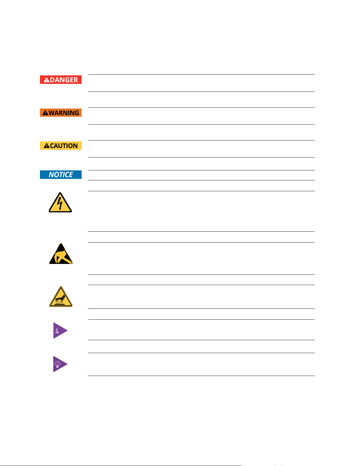
DANGER indicates a hazardous situation which, if not avoided,
will result in death or serious injury.
WARNING indicates a hazardous situation which, if not avoided,
could result in death or serious injury.
CAUTION indicates a hazardous situation which, if not avoided,
may result in minor or moderate injury.
NOTICE indicates a property damage message.
Electric Shock!
This symbol and title warn of hazards due to electrical shocks (> 60 V) when touching
products or parts of them. Failure to observe the precautions indicated and/or prescribed by
the law may endanger your life/health and/or result in damage to your material.
Please refer also to the "High-Voltage Safety Instructions" portion below in this section.
ESD Sensitive Device!
This symbol and title inform that the electronic boards and their components are sensitive
to static electricity. Care must therefore be taken during all handling operations and
inspections of this product in order to ensure product integrity at all times.
HOT Surface!
Do NOT touch! Allow to cool before servicing.
This symbol indicates general information about the product and the user manual.
This symbol also indicates detail information about the specific product configuration.
This symbol precedes helpful hints and tips for daily use.

mITX-KBL-S-C236 Doc. Rev. 1.6
www.kontron.com // 6
Table of Contents
Symbols .................................................................................................................................................................................................................5
Table of Contents ...............................................................................................................................................................................................6
List of Tables........................................................................................................................................................................................................7
List of Figures ......................................................................................................................................................................................................7
1/ Introduction............................................................................................................................................................................................9
2/ Description............................................................................................................................................................................................10
3/ Installation procedure .......................................................................................................................................................................11
3.1. Packing Check List......................................................................................................................................................................................11
3.2. Installing the Board ..................................................................................................................................................................................11
3.3. Requirements IEC60950-1.....................................................................................................................................................................12
3.4. Lithium battery precautions.................................................................................................................................................................13
4/ System specifications.......................................................................................................................................................................14
4.1. Functional Block Diagram ......................................................................................................................................................................14
4.2. Component Main Data............................................................................................................................................................................15
5/ Jumpers and Connectors .................................................................................................................................................................18
5.1. Hardware Configuration Setting ..........................................................................................................................................................18
5.1.1. Jumpers and Connectors......................................................................................................................................................................18
5.2. Mainboard Placement and Rear I/O locations................................................................................................................................19
5.3. Rear Side......................................................................................................................................................................................................21
6/ Pin Definitions.....................................................................................................................................................................................22
6.1. Processor Support...................................................................................................................................................................................23
6.2. System Memory Support......................................................................................................................................................................23
6.3. Ethernet Connectors (I/O area)..........................................................................................................................................................24
6.4. USB Connectors (I/O area)................................................................................................................................................................... 25
6.5. Audio Jack Connectors (I/O area)....................................................................................................................................................... 27
6.6. Fan Connectors (internal).....................................................................................................................................................................28
6.7. Front Panel 1 (internal)..........................................................................................................................................................................29
6.8. COM1/COM2 Internal ............................................................................................................................................................................30
6.9. Kontron Feature Connector (GPIO Internal) ....................................................................................................................................31
6.10. CMOS1 Jumper ........................................................................................................................................................................................32
6.11. Always ON Jumper .................................................................................................................................................................................32
6.12. LCD_PWR1 Internal................................................................................................................................................................................ 33
6.13. LVDS (internal)........................................................................................................................................................................................33
6.14. SATA (Serial ATA) Disk Interfaces (internal) ................................................................................................................................34
7/ Features and Power Supply........................................................................................................................................................... 35
7.1. Onboard Power Supply........................................................................................................................................................................... 35
7.2. External Power Supply .......................................................................................................................................................................... 35
7.3. Power Management ...............................................................................................................................................................................36
7.4. Real-Time Clock .......................................................................................................................................................................................36
7.5. Trusted Platform Module (TPM) ........................................................................................................................................................36
8/ BIOS Setup structure........................................................................................................................................................................ 37
8.1. Main Setup Menu ..................................................................................................................................................................................... 37
8.2. Advanced Setup Menu........................................................................................................................................................................... 37
8.3. Chipset Setup Menu.................................................................................................................................................................................51
8.4. Security Setup Menu.............................................................................................................................................................................. 76
8.5. Boot Setup Menu.....................................................................................................................................................................................78
8.6. Save & Exit Setup Menu........................................................................................................................................................................ 78

mITX-KBL-S-C236 Doc. Rev. 1.6
www.kontron.com // 7
9/ Technical Support ............................................................................................................................................................................. 79
9.1. Warranty..................................................................................................................................................................................................... 79
9.2. Returning Defective Merchandise ..................................................................................................................................................... 79
List of Acronyms...............................................................................................................................................................................................81
About Kontron ..................................................................................................................................................................................................82
List of Tables
Table 1: Component Main Data ....................................................................................................................................................................15
Table 2: Environmental Conditions ............................................................................................................................................................17
Table 3: Certification and Compliance Information ..............................................................................................................................17
Table 4: Connector Definitions....................................................................................................................................................................22
Table 5: Processor Support..........................................................................................................................................................................23
Table 6: Memory Support.............................................................................................................................................................................23
Table 7: Pin Assignment DP Connector ....................................................................................................................................................24
Table 8: Signal Description...........................................................................................................................................................................24
Table 9: Pin Assignment................................................................................................................................................................................ 25
Table 10: Signal Description......................................................................................................................................................................... 25
Table 11: Pin Assignment (Line Out, green) ............................................................................................................................................. 27
Table 12: Pin Assignment (Line In, blue)................................................................................................................................................... 27
Table 13: Pin Assignment (Mic In, pink).................................................................................................................................................... 27
Table 14: Signal Description......................................................................................................................................................................... 27
Table 15: 4-pin Mode......................................................................................................................................................................................28
Table 16: Signal Description.........................................................................................................................................................................28
Table 17: FP1 Connector .................................................................................................................................................................................29
Table 18: COM1/2 Internal Connection .....................................................................................................................................................30
Table 19: Signal Description.........................................................................................................................................................................30
Table 20: Pinout GPIO......................................................................................................................................................................................31
Table 21: CMOS1 Internal Connection........................................................................................................................................................32
Table 22: Always ON Jumper .......................................................................................................................................................................32
Table 23: LCD_PWR1 Internal Connection............................................................................................................................................... 33
Table 24: LVDS Pin Assignment.................................................................................................................................................................. 33
Table 25: Pin Assignment..............................................................................................................................................................................34
Table 26: Signal Description ........................................................................................................................................................................34
Table 27: Power States..................................................................................................................................................................................36
Table 28: Main Setup Menu Sub-Screens Functions........................................................................................................................... 37
Table 29: Advanced Setup Menu Sub-Screens and Functions......................................................................................................... 37
Table 30: Chipset Setup Menu Functions.................................................................................................................................................51
Table 31: Security Setup Menu Functions............................................................................................................................................... 76
Table 32: Boot Priority Order.......................................................................................................................................................................78
Table 33: Save & Exit Setup Menu Functions......................................................................................................................................... 78
List of Figures
Figure 1: Functional Block Diagram ............................................................................................................................................................14
Figure 2: Front Side and Interfaces.............................................................................................................................................................19
Figure 3: Rear View with Interfaces ..........................................................................................................................................................20
Figure 4: Bottom Side......................................................................................................................................................................................21
Figure 5: Ethernet Connector.......................................................................................................................................................................24
Figure 6: USB 2.0 / 3.0 socket...................................................................................................................................................................... 25
Figure 7: USB 2.0 High Speed Cable...........................................................................................................................................................26
Figure 8: USB 3.0 High Speed Cable...........................................................................................................................................................26
Figure 9: Audio Jack......................................................................................................................................................................................... 27
Figure 10: 4-pin Fan Connector...................................................................................................................................................................28
Figure 11: FP1 Connector ................................................................................................................................................................................29

mITX-KBL-S-C236 Doc. Rev. 1.6
www.kontron.com // 8
Figure 12: 9-pin COM1/2 Internal Connector (2 mm raster)..............................................................................................................30
Figure 13: GPIO Internal Connector .............................................................................................................................................................31
Figure 14: CMOS1 Jumper ..............................................................................................................................................................................32
Figure 15: Always ON Jumper.......................................................................................................................................................................32
Figure 16: LCD_PWR1 Internal Connector ................................................................................................................................................ 33
Figure 17: LVDS Connector ............................................................................................................................................................................33
Figure 18: SATA Connector ...........................................................................................................................................................................34
Figure 19: Available Cable Kit.......................................................................................................................................................................34

mITX-KBL-S-C236 Doc. Rev. 1.6
www.kontron.com // 9
1/ Introduction
This manual describes the Mini ITX 8th generation S-C236 board. This board will also be denoted mITX-KBL-S-C236
within this Users Guide.
The use of this Users Guide implies a basic knowledge of PC hard- and software. This manual is focussed on
describing the mITX-KBL-S-C236 board’s special features and is not intended to be a standard PC textbook.
New users are recommended to study the short installation procedure stated in the following chapter before
switching-on the power.
All configuration and setup of the CPU board is either done automatically or manually by the user via the BIOS setup
menus.
Latest revision of this manual, datasheet, thermal simulations, BIOS, drivers, BSP’s (Board Support Packages) can be
downloaded from Kontron Web Page.

mITX-KBL-S-C236 Doc. Rev. 1.6
www.kontron.com // 10
2/ Description
The mainboard mITX-KBL-S-C236 is based on the 8th generation processor family. It uses the Chipset C236 PCH
from Intel. This powerful hardware with efficient graphic and network capabilities offers a broad range of
application areas. The processor, graphics and memory controller is built on 22 nm die.
Main characteristics are:
Support 8th generation processors with LGA1151 CPU Socket (37.5 mm x 37.5 mm)
Range from 65 to 80 W TDP
Intel®KBL C236 PCH chipset
2x ECC/NON ECC SODIMM Memory Architecture
Max. three displays by Display Port: 3x DP and LVDS (optional)
Three Gigabit Ethernet ports
ECC memory optional
Four SATA 3.0 Ports
M.2 and PCIe minicard
Built with these functions, mITX-KBL-S-C236 Mother Board is ideal for ATM, Automation, Kiosk applications, medical
equipment, industrial automation, financial automation, process control, semiconductor equipment, and network
security markets.
mITX-KBL-S-C236 Doc. Rev. 1.6
www.kontron.com // 11
3/ Installation procedure
3.1. Packing Check List
The mITX-KBL-S-C236 package includes the following basic items accompany with this manual.
One main board
One IO shield
If any of these items is damaged or missed, please contact your vendor and save all packing materials for future
replacement and maintenance.
Note: The above packing list is for standard single box packing only.
3.2. Installing the Board
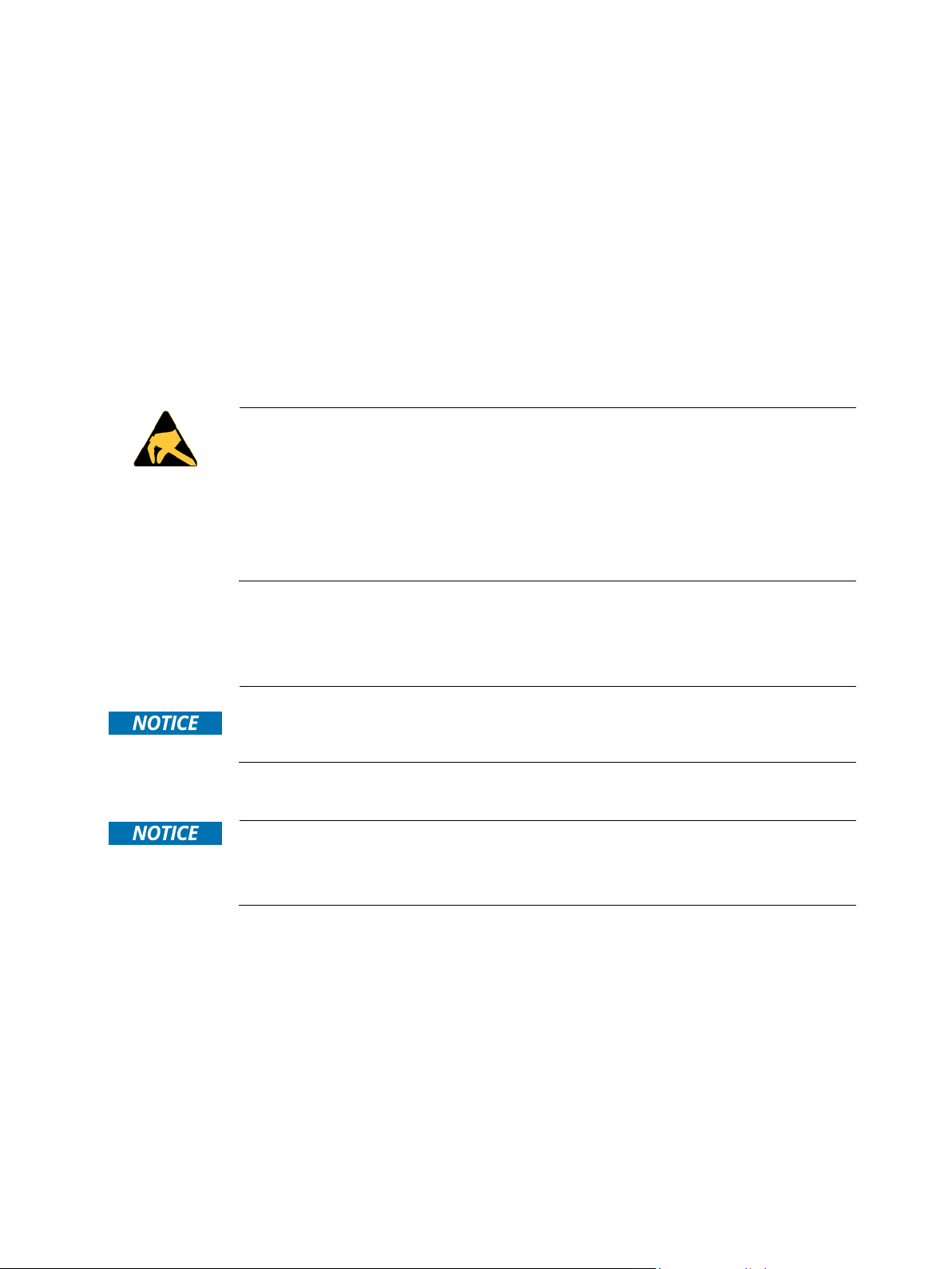
ESD Sensitive Device!
Electrostatic discharge (ESD) can damage equipment and impair electrical circuitry.
•Wear ESD-protective clothing and shoes
•Wear an ESD-preventive wrist strap attached to a good earth ground
•Check the resistance value of the wrist strap periodically (OK: 1 MΩto 10 MΩ)
•Transport and store the board in its antistatic bag
•Handle the board at an approved ESD workstation
•Handle the board only by the edges
To get the board running follow these steps. If the board shipped from Kontron has already components like RAM
and CPU cooler mounted, then relevant steps below can be skipped.
Only connect to a power supply delivering the specified input rating and complying with the
requirements of Safety Extra Low Voltage (SELV) and Limited Power Source (L.P.S.) of IEC
60950-1 and the Energy sources (ES1) of IEC 62368-1.
1.
Turn off the PSU (Power Supply Unit)
Turn off PSU (Power Supply Unit) completely (no mains power connected to the PSU)
or leave the Power Connectors unconnected while configuring the board. Otherwise
components (RAM, LAN cards etc.) might get damaged. Make sure to use +12V single supply
only. Alternatively use a standard ATX PSU with suitable cable kit and PS_ON# active.
2.
Insert the DDR4 SO-DIMM 260 pin module(s)
Be careful to push it in the slot(s) before locking the tabs. For a list of approved SO-DIMMs contact your
Distributor or FAE. See also chapter “System Memory Support”. Use SO-DIMM with the same memory density in
both sockets!
3.
Processor installation
Install the processor in the processor connector. Follow the steps in the delivered manual from the processor
manufacturer.
4.
Cooler Installation
You can connect the cooler fan electrically to the FANCPU connector.
mITX-KBL-S-C236 Doc. Rev. 1.6
www.kontron.com // 12
5.
Connecting Interface
s
Insert all external cables for hard disk, keyboard etc. A monitor must be connected in order to change BIOS
settings.
6.
Connect and turn on PSU
Connect PSU to the board by the External Power of ATXPWR (20 poles power plug) and Internal Power of ATX4p
(4 poles power plug) to the I/O Power jack.
7.
Power Button
If the board does not start by itself when switching on the ATX/DC PSU AC mains, then follow these instructions
to start the board. I
8.
BIOS Setup
Enter the BIOS setup by pressing the <F2> key during boot up.
Enter “Exit Menu” and Load Setup Defaults.
Refer to the “BIOS Configuration / Setup“ section of this manual for details on BIOS setup.
To clear all BIOS settings, including Password protection, activate “Load Default BIOS
Settings” Jumper for >
10 sec (without power connected).
9. Mounting the board in chassis
When mounting the board to chassis etc. please notice that the board contains components
on both sides of the PCB which can easily be damaged if board is handled without
reasonable care. A damaged component can result in malfunction or no function at all.
When fixing the Motherboard on a chassis it is recommended to use screws with integrated washer and a
diameter of >7 mm. Do not use washers with teeth, as they can damage the PCB and cause short circuits.
3.3. Requirements IEC60950-1
Take care when designing chassis interface connectors in order to fulfil the IEC60950-1 standard.
Users of mITX-KBL-S-C236 must evaluate the end product to ensure compliance the requirements of the IEC60950-
1 safety standard are met:
The motherboard must be installed in a suitable mechanical, electrical and fire enclosure.
The system in its enclosure must be evaluated for temperature and air flow considerations.
The motherboard must be powered by a CSA or UL approved power supply that limits the maximum input current to
10 A via external barrel-type 12-24 VDC connector, and to 16 A via internal square 12 VDC ATX connector.
For interfaces having a power pin such as external power or fan, ensure that the connectors and wires are suitably
rated. All connections from/to the product shall be with SELV circuits only.
Wires have suitable rating to withstand the maximum available power.
The enclosure of the peripheral device fulfils the fire protecting requirements of IEC60950-1.

mITX-KBL-S-C236 Doc. Rev. 1.6
www.kontron.com // 13
3.4. Lithium battery precautions
Danger of explosion if the lithium battery is incorrectly replaced.
•Replace only with the same or equivalent type recommended by the manufacturer
•Dispose of used batteries according to the manufacturer’s instructions
VORSICHT! Explosionsgefahr bei unsachgemäßem Austausch der Batterie.
•Ersatz nur durch denselben oder einen vom Hersteller empfohlenen gleichwertigen
Typ
•Entsorgung gebrauchter Batterien nach Angaben des Herstellers
ATTENTION! Risque d'explosion avec l'échange inadéquat de la batterie.
•Remplacement seulement par le même ou un type équivalent recommandé par le
producteur
•L'évacuation des batteries usagées conformément à des indications du fabricant
PRECAUCION! Peligro de explosión si la batería se sustituye incorrectamente.
•Sustituya solamente por el mismo o tipo equivalente recomendado por el fabricante
•Disponga las baterías usadas según las instrucciones del fabricante
ADVARSEL! Lithiumbatteri – Eksplosionsfare ved fejlagtig håndtering.
•Udskiftning må kun ske med batteri af samme fabrikat og type
•Levér det brugte batteri tilbage til leverandøren.
ADVARSEL! Eksplosjonsfare ved feilaktig skifte av batteri.
•Benytt samme batteritype eller en tilsvarende type anbefalt av apparatfabrikanten.
•Brukte batterier kasseres i henhold til fabrikantens instruksjoner
VARNING! Explosionsfara vid felaktigt batteribyte.
•Använd samma batterityp eller en ekvivalent typ som rekommenderas av
apparattillverkaren.
•Kassera använt batteri enligt fabrikantens instruktion.
VAROITUS! Paristo voi räjähtää, jos se on virheellisesti asennettu.
•Vaihda paristo ainoastaan lalteval- mistajan suosittelemaan tyyppiln
•Hävitä käytetty paristo valmistajan ohjeiden mukaisesti
mITX-KBL-S-C236 Doc. Rev. 1.6
www.kontron.com // 14
4/ System specifications
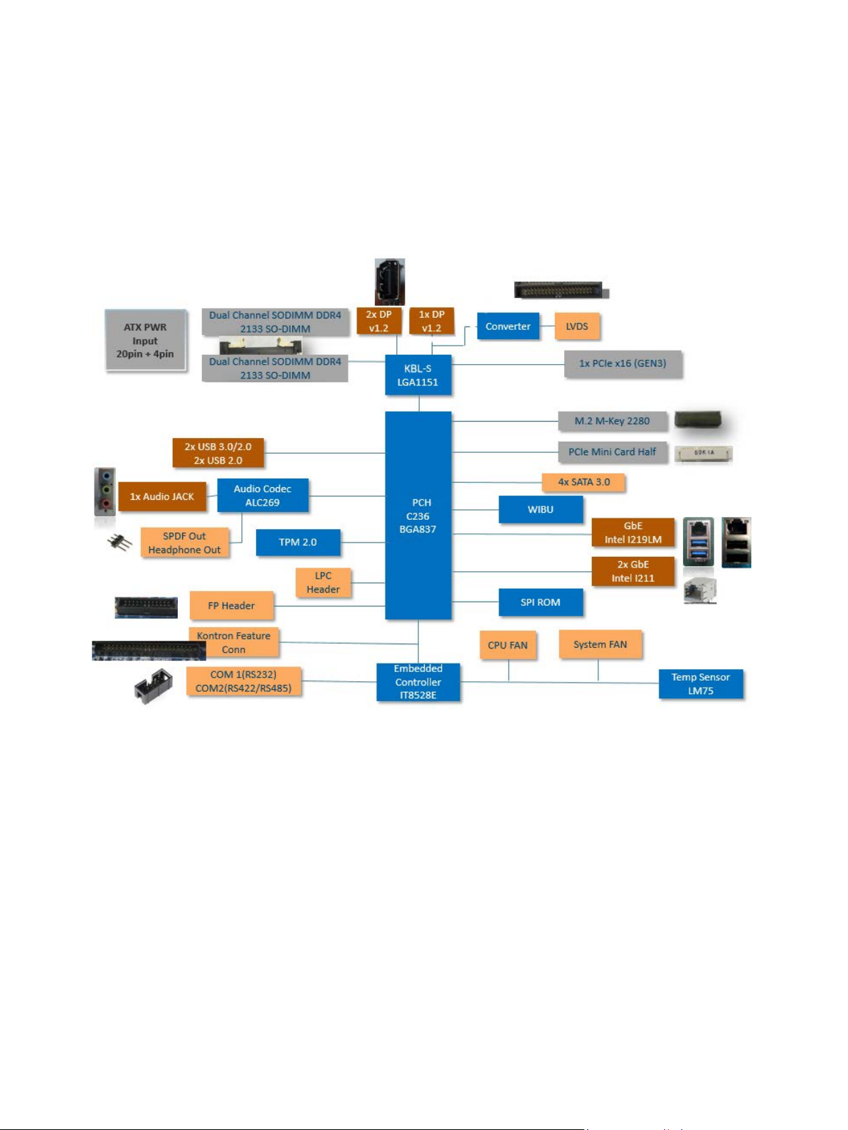
4.1. Functional Block Diagram
Figure 1: Functional Block Diagram

mITX-KBL-S-C236 Doc. Rev. 1.6
www.kontron.com // 15
4.2. Component Main Data
The table below summarizes the features of the mITX-KBL-S-C236 embedded motherboard.
Table 1: Component Main Data
Motherboard mITX-KBL-S-C236
Form factor Mini ITX (170.18 mm by 170.18 mm)
Processor Onboard CPU variants
Intel® 8th generation S Processor line, LGA1151 CPU Socket (37.5 mm x 37.5 mm)
Range from 65 to 80 W TDP, Core™ i7-7700, Core™ i5-7500, Core™ i3-7101E, Xeon®
Processor E3-1275 v6
BIOS AMI UEFI BIOS with128Mb SPI Flash ROM support AMT11.0
PCH Intel®KBL PCH 236 series
I/O Control ITE IT8528E/FX (Kontron EC)
Memory 2x Dual-Channel DDR4 SO-DIMM with ECC, Support DDR4 (1.2 V) 2133 MT/s (PC4-2133),
max. up to 32
GB memory using 2x16
GB modules
Storage 4x SATA 3.0
Watchdog Timer Reset; 1 sec.~255 min. and 1 sec. or 1 min./step
Wake On Wake on LAN, USB, Power button
Hardware Status
Monitor
Monitoring CPU and system temperature, voltage status and fan speed
TPM Kontron TPM 2.0 support via SPI / USB interface
Power
management
Support S5, S4, S3, S0
Battery CR2032, 220 mAh
See Safety Instructions below this table!
Expansion One PCIe x16 slot (PCIe Gen3)
Operating System
Support
Windows 10
External I/O
LAN , USB3.0 3x RJ-45 LAN Port (with two LED indicators) + dual USB3.0 + dual USB2.0 (4x USB)
Audio 3x Audio Jacks for MIC-input, Line-out and Line-input
Display Port (DP) 2x Display Port connector Version 1.2 (optional 3x DP)
Internal I/O
SATA 4x SATA3.0 (6
Gb/s)
M.2 2280 M-key with PCIe x1 (default) or SATA (option)
PC Buzzer Standard PC buzzer on board
USB 2x Front I/O (Front Panel Internal Header), supports 2x USB 2.0
Serial Peripheral
Interface (SPI)
For optional fast General Purpose IO (GPIO) on component side
LVDS 1x ( 2x 20 ) 1.25
mm pin-header for 24-bit dual channel with brightness control
Mini PCIe 1x for half size
Audio 1x 3-pin SPDF and 1x 3-pin Headphone Out
Serial 1x RS232, 1x RS485/RS422
Internal Header
Fan Power 2x (1x 4 ) 2.54
mm pin-header for CPU & System fan with PWM function

mITX-KBL-S-C236 Doc. Rev. 1.6
www.kontron.com // 16
CMOS Clear 1x 3 2
mm pin-header
Front Panel 1x 24 pin connector
LCD Power/Always
ON
2x 3 2.0 mm pin-header;
PS/2 1x 2.0
mm pin-header (for installing Windows)
Display
Graphics Controller
Intel®Gen 9 LP (generation 9 Low Power) graphics core with three pipes and 72 Execution
Units
Supports DirectX 11,Direct3D* 2015, Direct3D 11.2, Direct3D 11.1, Direct3D 9, Direct3D
10, Direct2D, OpenGL* 5.0,OpenCL* 2.1, OpenCL 2.0, OpenCL 1.2.
Supports full HW accelerated video decoding for AVC/H.264, MPEG2, VC1/WMV9,
VP8, JPEG/MJPEG, HEVC/H265, VP9
Supports full HW accelerated video encoding for H.264, MPEG2, VP8, JPEG,
HEVC/H265m VP9
two 4k DisplayPorts (optional 3), LVDS optional
DP to LVDS
Controller
NXP PTN3460
Display Interface two Display Ports, optional LVDS resp. third DP-Port (optional)
Note: Three (3) Independent Displays Max.
Resolution DP/LVDS 4096x2304 @ 60
Hz, 24
bpp (One panel display)
Ethernet
Controller LAN1: Intel® I219LM 10/100/1000 Gigabit Ethernet PHY with AMT11.0
LAN2 and LAN3: Intel® I211AT 10/100/1000 Gigabit Ethernet Controller
Interface IEEE 802.3 10BASE-T/100BASE-TX/1000BASE-T compliant
Audio
HDAC Realtek®ALC269Q High Definition Audio Codec
Power Supply
Power Type 4-pin ATX 12V power connector
and :
20-pin ATX Power connector
Danger of explosion if the lithium battery is incorrectly replaced.
•Replace only with the same or equivalent type recommended by the manufacturer
•Dispose of used batteries according to the manufacturer’s instructions

mITX-KBL-S-C236 Doc. Rev. 1.6
www.kontron.com // 17
Table 2: Environmental Conditions
Operating 0°C to +60°C (32°F~140°F) operating temperature (forced cooling).
It is the customer’s responsibility to provide sufficient airflow around each of the
components to keep them within allowed temperature range. Please refer to the thermal
simulation report for information about airflow.
10% to 90% relative humidity (non-condensing)
Storage -20°C~70°C (-4°F~176°F); lower limit of storage temperature is defined by specification
restriction of on-board CR2032 battery.
Board with battery has been verified for storage temperature down to -40 C by Kontron.
Up to 95
% relative humidity (temperature 25°C to 30°C)
Radiated Emissions
(EMI)
All Peripheral interfaces intended for connection to external equipment are EMI protected.
EN 61000-6-4:2007 (EMC) Generic emission standard Part 6-4: Emission standard for
industrial environments
Safety EN 60950-1:2006 +A11:2009 +A1:2010 +A12:2011:
Safety for information technology equipment including electrical business equipment
Shock IAW IEC 60068-2-27, Half-sine wave, Acceleration: 2g, Pulse duration: 11ms, number of
shocks: 600 shocks (100 shocks for each face)
Vibration AW IEC 60068-2-64, test Fh, Random Vibration, 90 min per axis, 3 axes at 1.9 grms, with
PSD: 10-20Hz: 0.05 g²/Hz and 20-500Hz:- 3dB/octave.
Restriction of
Hazardous
Substances (RoHS)
All boards in the mITX-KBL family are RoHS compliant
MTBF 15 years
Altitude 2000 m max., optionally 3000m
Table 3: Certification and Compliance Information
UL E147705-A96-UL: Equipment Including Electrical Business Equipment
CE EMC Directive 2014/30/EU
EN55032/EN55024
Low Voltage
Directive
2014/35/EU
FCC FCC 47 CFR Part 15 Subpart B
ANSI C63.4:2014
ISED ICES-003 (Issue 6)
CE EMC EN 55032:2012/AC:2013, Class B
CISPR 32:2012
EN 61000-3-2:2014
EN 61000-3-3:2013
EN 55024:2010 + A1:2015
FCC DoC FCC 47 CFR Part 15 Subpart B
ICES-003 Issue 6-2016
ANSI C63.4-2014

mITX-KBL-S-C236 Doc. Rev. 1.6
www.kontron.com // 18
5/ Jumpers and Connectors
5.1. Hardware Configuration Setting
This chapter gives the definitions and shows the positions of jumpers, headers and connectors. All of the
configuration jumpers on the board are in the proper position. The default settings shipped from factory are marked
with an asterisk (*).
In general, jumpers on the board are used to select options for certain features. Some of the jumpers are designed to
be user-configurable, allowing for system enhancement. The others are for testing purpose only and should not be
altered. To select any option, cover the jumper cap over (SHORT) or remove (NC) it from the jumper pins according to
the following instructions. Here, NC stands for “Not Connect”.
5.1.1. Jumpers and Connectors
Jumpers Function Remark
CLR_CMOS1 Clear CMOS 1x 3 header
Always_ON Always On Jumper 1x 3 header
LCD_PWR1 LCD PWR 1x 3 header
Connectors Function Remark
CPU_FAN1 CPU FAN Connector 1x 4 wafer
SYS_FAN1 SYS FAN Connector 1x 4 wafer
FP1 Front Panel Connector 2x 12 header
SPKR Speaker Connector 1x 4 wafer
GPIO GPIO Port Connector 2x 5 box header
LCD_BKL LCD Backlight Connector 1x 5 wafer
LVDS LVDS Connector 2x 20 connector
ATX ATX Power Connector 2x 10 connector
COM1/COM2 Internal COM1/COM2 2x 9-pin connector
PWR_CPU1 CPU Power Connector 2x 2-pin connector
MINI-PCIE Mini PCIe Connector 2x 26 connector
PCIEx16X PCIe x16 Connector 1x
SPI_SOCKET Bios Socket 2x 12 connector
SATA1 SATA3.0 Connector Standard
SATA2 SATA3.0 Connector Standard
SATA3 SATA3.0 Connector Standard
SATA4 SATA3.0 Connector Standard
BAT54 Battery Socket CR2032 compatible
DIMM1 Memory Socket Slot
DIMM2 Memory Socket Slot
mITX-KBL-S-C236 Doc. Rev. 1.6
www.kontron.com // 19
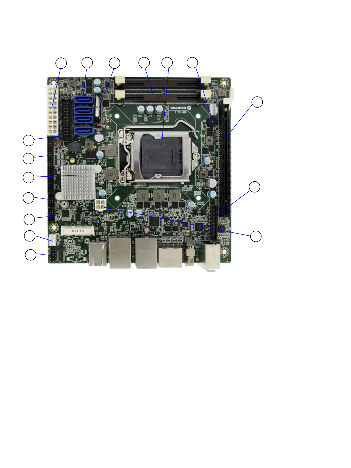
5.2. Mainboard Placement and Rear I/O locations
Figure 2: Front Side and Interfaces
1. ATX 12 V power interface
2. SATA connector
3. Battery holder
4. Memory connector
5. CPU connector
6. Speaker
7. PCIe connector
8. LVDS Connector
9.
ATX-4-pin Power connector
10. LPC1 Bus
11. Sys-Fan
12. COM2/COMB1 RS-232
13. COM1/COMA1 RS232/422/485
14. PCH chip controller
15. GPIO feature connector
16. 24-pin Front Panel Header
1
2 4 65
10
9
8
7
14
13
3
11
12
15
16
mITX-KBL-S-C236 Doc. Rev. 1.6
www.kontron.com // 20
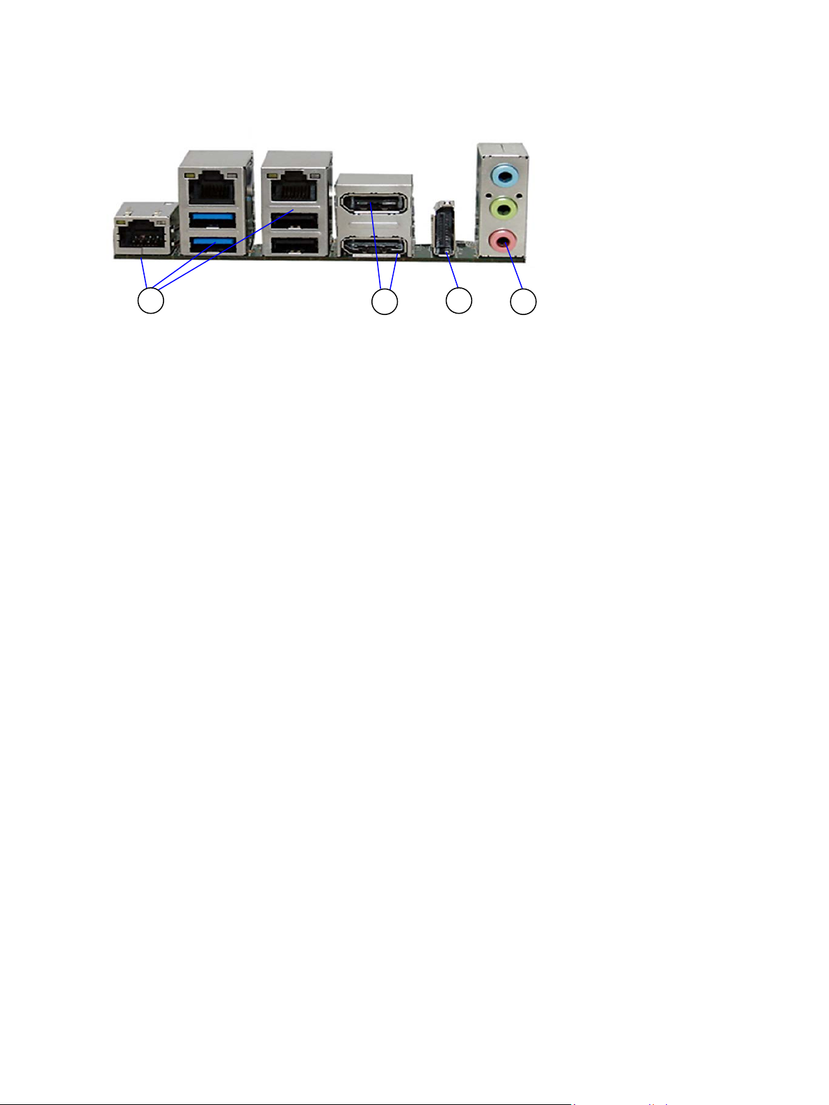
Figure 3: Rear View with Interfaces
17. 4xUSB/3xEthernet
18. 2x Display Port
19. 1x DisplayPort (optional)
20. Audio jacks
17
19
20
18
Table of contents
Other S&T Motherboard manuals


