Saniflo SANI12661 Instructions for use

SANIALARM INTERLOCK
OWNER’S
OPERATION MANUAL
MODEL: SANI12661
DOC: SANI12661 VER 1.0
AUSTRALIA/NEW ZEALAND
SANIFLO (Australia)
Unit 10, 25 Gibbes Street
Chatswood, NSW 2067
Tel: 1300 554 779 (AU)
Tel: 0800 107 264 (NZ)

2
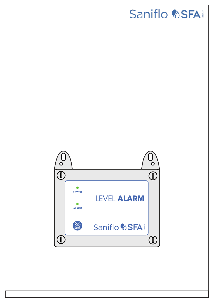
WELCOME TO UNDERSINK/SULLAGE CHAMBER ALARM
Your Under-sink/Sullage Chamber Alarm reflects the superior quality and attention to detail in design, engineering
and manufacturing that has distinguished SANIFLO Products for decades. The controller incorporates the very
latest in micro-processor technology, ensuring you, the owner/operator, of many years of functional, reliable and
‘user friendly’ operation.
Please read this manual prior to installation and operation of the controller.
SAFETY 2
FUNCTIONAL OVER VIEW 3
OPERATIONS 3
SCHEMATIC 3
CONNECTION DETAILS 4
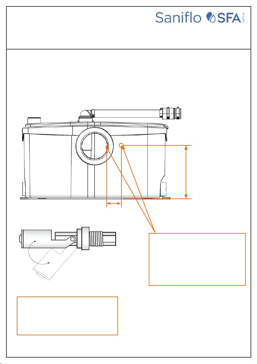
MAGNETIC FLOAT SWITCH FITTING GUIDE 5
WIRING DIAGRAM 10
CONTENTS
SAFETY
• Prior to Installation, ensure power supply is isolated.
• Power supply must be RCD Protected. (Qualied Electrician to determine appropriate amp rating.)
• Electrical connection to the panel must be carried out in accordance with ‘Connection Instructions’, see page 4.
• Addition or modications to the control panel are not permitted and will void warranty.
• The controller is not intended for use by children or inrm persons without supervision.
• Repairs to the Controller must only be carried out by a suitably qualied Electrician
WARNING: All electrical connections must be carried out by a suitably qualied and
registered electrician

3
UNDERSINK / SULLAGE
CHAMBER ALARM
SANIALARM INTERLOCK - WITH VALVE & DISHWASHER INTERLOCK
FUNCTIONAL OVERVIEW
SCHEMATIC
NOTE:
OUTLET
OPERATION
TO SEWER
MAINS WATER
DRAIN
DRAIN
MAINS WATER
POWER
SUPPLY TO
DISWASHER

4
UNDERSINK / SULLAGE
CHAMBER ALARM
SANIALARM INTERLOCK - WITH VALVE & DISHWASHER INTERLOCK
CONNECTION DETAILS
1. Ensure power to the unit is disconnected before carrying out installation.
2. Mount Panel in a dry area and in a vertical position so that cable connections are on the underside of the panel.
3. Ensure valve is installed in accordance with local Plumbing Codes.
4. Install Float Switch in tank as indicated in supplied tting guide.
5. Plug dishwasher into power outlet provided. (See Figure 1)
NOTE: DO NOT PLUG PUMP INTO THIS POWER OUTLET
6. Plug the unit’s power lead into RCD protected GPO, and switch power on.
7. Your unit is now ready for use.
Figure 1
Quick Plug
Float Switch
Connection
Quick Plug
Valve Connection
Dishwasher Power
Lead

5
SANIALARM INTERLOCK
MAGNETIC FLOAT SWITCH
FITTING GUIDE
USE MAGNETIC FLOAT SWITCH SUPPLIED WITH SANIALARM INTERLOCK ONLY
Drill a 22mm hole and insert the
probe here, make sure the hole is
60mm down from the top of the grey
cabinet and 60mm from the side.
SANICOM 1
Please ensure that the magnetic oat
switch is positioned as shown above,
with the arm swinging down inside the
pump case
SANIVITE / SANISPEED +
Drill 22mm hole 60mm in from the LH
side of the case by 60mm down from
the top of the lid to insert the magnetic
nger oat switch

6
SANIALARM INTERLOCK
MAGNETIC FLOAT SWITCH
FITTING GUIDE
Drill a 22mm hole 185mm from the LH side
of case by 65mm down from the top of the
lid to insert the magnetic nger switch
Drill a 22mm hole and insert the probe here,
make sure the hole is 110mm down from
the top and 140mm from the side.
Please ensure that the magnetic oat switch is
positioned as shown above, with the arm
swinging down inside the pump case.
USE MAGNETIC FLOAT SWITCH SUPPLIED WITH SANIALARM INTERLOCK ONLY
SANIPACK PRO UP
SANIACCESS 3

7
Please ensure that the magnetic oat switch is
positioned as shown above, with the arm
swinging down inside the pump case.
SANIALARM INTERLOCK
MAGNETIC FLOAT SWITCH
FITTING GUIDE
USE MAGNETIC FLOAT SWITCH SUPPLIED WITH SANIALARM INTERLOCK ONLY
SANITOP 70mm
180mm
Drill a 22mm hole and insert the
probe here, make sure the hole is
180mm up from the bottom of the
case and 70mm from the outside
edge to centre

8
SANIALARM INTERLOCK
MAGNETIC FLOAT SWITCH
FITTING GUIDE
USE MAGNETIC FLOAT SWITCH SUPPLIED WITH SANIALARM INTERLOCK ONLY
SANIACCESS 2
Please ensure that the magnetic oat switch is
positioned as shown above, with the arm
swinging down inside the pump case.
170mm
Drill a 22mm hole and insert the
probe here, make sure the hole is
170mm up from the bottom and
120mm from the side.

9
Please ensure that the magnetic oat switch is
positioned as shown above, with the arm
swinging down inside the pump case.
SANIALARM INTERLOCK
MAGNETIC FLOAT SWITCH
FITTING GUIDE
USE MAGNETIC FLOAT SWITCH SUPPLIED WITH SANIALARM INTERLOCK ONLY
SANIBEST PRO
170mm
25mm
Drill a 22mm hole and insert the probe here,
make sure the hole is 170mm up from the
bottom of the case and 25mm from the inside
edge of the spigot connector opening.

10
CIRCUIT DIAGRAM
ME26
P GM
KEYPAD
LATCHI NG
MUTE
INPUT INPUT INPUT VALVE
B A - +
A N E E A N
PUMP SUPPLY
C NC
AUX
C NO
OUTPUT
NO
S ELF RE SE T5 M IN TIM EO UT
CON TI NUOUS
ST RO BE
- +
SIREN
- +
ALARM
ON
1 2
COM -12652
ME26
P GM
KEYPAD
LATCHI NG
MUTE
INPUT INPUT INPUT VALVE
B A - +
A N E E A N
PUMP SUPPLY
C NC
AUX
C NO
OUTPUT
NO
S ELF RE SE T5 M IN TIM EO UT
CON TI NUOUS
ST RO BE
- +
SIREN
- +
ALARM
ON
1 2
COM -12652
240 Vac
Supply Plug
240N
BuzzerBuzzer
Valve
GPO1GPO1 GPO Flush Mount
10Amp
GPO1 GPO Flush Mount
10Amp
Quickplug
Float
Quickplug
Float
Female
Connection
Female
Connection
Male ConnectionMale Connection
Horizontal
Magnetic Pivot
Float Switch

11
ARRANTY CONDITIONS
This device is guaranteed for 2 years from the date of purchase and is subject to:
• ACL(2) 2010 in Australia, or NZ CG Act 1993 in New Zealand, if used for personal, domestic or household use
• Installation in strict compliance with manufacturers installation manual in the product box
This warranty does not cover the following which remain at the risk, cost and responsibility of the owner:
• Costs of travel and transport or insurance of the device
• Device installed outside 50km radius from an accredited Saniflo Agents Office
• All costs necessary to safely access and replace the installed device including costs of additional plant equipment,
materials, handling and/or safety equipment
• This warranty is not transferable
• This warranty shall not apply when the product is sold or installed outside Australia or New Zealand
NOTE: Warranty only applies when the Sanialarm Interlock is used with Saniflo SFA products

12
NOTES
Table of contents