Sanken C Series User manual

2
SANKEN ELECTRIC CO., LTD. December 2016PAN40004-001E-02
Table of Contents
Safety Precautions 3
Appearance and Meaning of Safety Warnings 4
Hazard and Caution Safety Warnings 5
Introduction to C Series 8
Names of Product Parts 9
Model Number Description 10
Input and Output Terminals, Connectors, and Pin Assignments 11
Block Diagrams 15
Functional Description 16
Parallel Operation 16
Input Voltage Range, Harmonic Current, and Inrush Current 17
Input voltage range 17
Harmonic current 17
Inrush current 17
Protection Functions 17
Overcurrent protection (OCP) 17
Overvoltage protection (OVP) 17
Thermal shutdown protection 17
Alarm Functions 18
PR signal 18
LV-Alarm signal 18
Output voltage adjustable range and remote sensing 20
Output voltage adjustable range 20
Remote sensing 20
Remote on/off control 21
Installation and De-Installation 22
DC module connection 22
DC module disconnection 23
Base power unit installation 24
Derating 25
Mounting Dimensions – C300 26
Mounting Dimensions – C450 27
Mounting Dimensions – C650 28
This paper is prepared as of December 2016 and subject to change without notice.
Downloaded from Arrow.com.Downloaded from Arrow.com.

3
SANKEN ELECTRIC CO., LTD. December 2016PAN40004-001E-02
!
Safety Precautions
Be sure to observe the precautions explained below.
1. Be sure to read this complete document and the detailed
specifications of the individual products in the product series
before using the product.
2. The products should be handled only by persons who have
competent electrical knowledge.
3. The products are DC stabilized power supplies with spe-
cial structures created for mounting on devices, please
implement safety design of the devices under customers'
responsibility not to endanger human life, health and
property due to malfunction and/or failures of the products
when using.
Although Sanken strives to improve the quality and the
4.
reliability of the products, please implement safety designs
that comply or exceed all industry standards and all of
the regulatory requirements of the jurisdictions where the
products will be used. Safety designs for use of the products
are the responsibility of the customer or user. The customer
or user has the responsibility not to endanger human life or
health, or to damage property due to malfunction and/or
failures of the products when using them.
5.
Sanken products listed in this publication are NOT intended
to use for equipment and applications where extremely high
reliability is required such as aerospace equipment, nuclear
power-control stations and medical equipment, for which
there is enhanced risk that the products could endanger
human life or health due to malfunction and/or failures of the
products (Classified III or above per GHTF, Global
Harmonization Task Force, Medical Equipment Class)
Sanken assumes no responsibility for any damage to any
customer and/or any third party due to use of Sanken
products for the such use.
6. When considering use of the products for the following
equipment and applications, for which there is the risk that
may heavily endanger human life or affect maintenance of
public function, be sure to secure sufficient fail-safe
function at customers' devices by means of multiplexing of
systems and other method.
• Electric trains and other conveyances such as elevators,
etc. that could result in personal injury
• Vehicles and vessels, etc. that could be affected by
vibration or shock
• Traffic systems, etc. that could exert an important
influence on society and the public
• Any other applications and equipment similar to those
mentioned above.
7.Be sure to observe the items below:
• Do not disassemble, repair, or modify these products.
• Do not touch inside of the products because of high
voltage.
• Use the products within the specified input voltage,
frequency, output voltage, and output current ranges.
• Be sure to observe designated ambient environment
conditions, such as ambient temperature and relative
humidity.
• Each product model has a designated method for
installation and mounting. Observe installation and
mounting instructions.
Downloaded from Arrow.com.Downloaded from Arrow.com.Downloaded from Arrow.com.

4
SANKEN ELECTRIC CO., LTD. December 2016PAN40004-001E-02
In this document, the levels of safety warnings are divided into
two categories, Hazard and Caution.
!
Hazard
Disregarding a Hazard display and incorrectly using the
product could result in death and/or serious injury.
!
Caution
Disregarding a Caution display and incorrectly using
the product could result in personal injury and/or
physical damage.
Be sure to observe the safety precautions indicated on the product
and in documentation by symbols and text. The general meaning
of symbols is as follows:
Prohibited action
!Strong warning
Electric shock hazard
Fire hazard
Appearance and Meaning of Safety Warnings
Downloaded from Arrow.com.Downloaded from Arrow.com.Downloaded from Arrow.com.Downloaded from Arrow.com.

5
SANKEN ELECTRIC CO., LTD. December 2016PAN40004-001E-02
Hazard and Caution Safety Warnings
General Cautionary Notices
!Hazard
• Shock hazard
• Never take off the cover.
• There is a high voltage circuit inside and touching it mistakenly could result in death and/or serious injury.
• Fire hazard
• If any abnormal odor or abnormal noise, or smoking or ignition arises in the product, immediately turn off
the product and cut the power input to the product by opening an external circuit breaker or other means.
• Please contact the vendor from which the product was purchased and/or Sanken.
• In case of fire, use a fire extinguisher of a powder/ABC type approved for use on electrical fires.
Note: Never use water.
Handling of Base Power Unit
!Caution
• Never install devices other than the designated Sanken DC modules into open slots in the products.
• Never insert your hand into open slots.
• The ground terminal of the product should be connected to earth ground correctly.
• Unless connected directly to earth ground, electric shock could result.
• Ensure that the grounding wire is connected directly to earth with a thick and short wire.
• Inside the base power unit is high voltage.
• Never disassemble, repair, or remodel the base power unit or touch directly inside it with your hands,
otherwise electric shock could result.
• The base power unit installation and mounting specifications are provided. Ensure that the base power unit
is installed according to the specifications.
• Do not install the base power unit incorrectly.
Downloaded from Arrow.com.Downloaded from Arrow.com.Downloaded from Arrow.com.Downloaded from Arrow.com.Downloaded from Arrow.com.

6
SANKEN ELECTRIC CO., LTD. December 2016PAN40004-001E-02
Handling of DC Modules
!Caution
Observe installation and mounting directions as described in the operation manual, otherwise fire or electric
shock due to failures, degradation, and so forth, could result.
!Turn the power source off and make sure that the supply of power has stopped before replacing the DC
module, otherwise fire or electric shock due to failures, degradation, and so forth, could result.
!DC modules could retain residual electrical charges and have a hot temperature after operation. Do not
touch them carelessly soon after powering them down, and be sure to let them cool down completely before
resuming operation.
!When taking out and putting in DC modules, make sure not to touch any components on the printed circuit
board (PCB), otherwise personal injury and/or damage to the products could result.
!When taking out DC modules, because connectors could be connected tightly, be careful not to cause
personal injury and/or damage to the products.
Do not take out or put in DC modules when the power supply is operating, otherwise it could cause damage
to the DC modules.
Be sure not to store DC modules on metal surfaces. If the back side of a DC modules is placed against a
metal surface, it could cause damage to the DC modules.
Make sure not to use DC module alone. When using DC modules, make sure to connect them with an
appropriate base power unit.
!When a load short-circuit and/or a short-circuit at start-up arise, damage to the products could result. Before
powering-up the products, please make sure to pay special attention to ensuring that no load short-circuit
condition exists.
Insulating Resistance and Withstand Voltage
!Caution
Be sure not to conduct withstanding voltage test without inserting Sanken DC modules. When applying
insulating resistance test and withstand voltage test, please consult with Sanken.
Downloaded from Arrow.com.Downloaded from Arrow.com.Downloaded from Arrow.com.Downloaded from Arrow.com.Downloaded from Arrow.com.Downloaded from Arrow.com.

7
SANKEN ELECTRIC CO., LTD. December 2016PAN40004-001E-02
Other Precautions
!Caution
Each power supply model has a designated input/output range. Be sure to use the products within
designated input/output range.
!Be sure that the total power consumption connecting with the load does not exceed the rated output
capacity per each power supply. If a power supply is used under an overload condition, it could cause fire.
Be sure to use thick wire for input/output wiring, and that it is appropriate for the input/output power. If thin
wires are used, it could cause fire.
Be sure not to use and/or store the products in temperature, humidity, and dew condensation conditions
beyond the ambient environmental conditions specified in the catalog and/or operation manual, otherwise
failure of the products could result.
!When the power supply is operated in dusty conditions, please apply dust proofing measures. The dust
could interfere heat dissipation and cause failure and/or fire.
!When the power supply is installed, be sure to use designated screws (paying particular attention to screw
length and diameter), otherwise electric shock and/or fire could result.
The products are not intended for use in equipment that requires high reliability for sustaining human life.
Be sure not to use the products for any particular application such as in nuclear reactor and/or power control
systems, aerospace applications, special Medical equipment, and so forth.
!When installing the products, be sure to connect each input terminal and output terminal without fail,
otherwise malfunction and damage to the products, personal injury, and fire could result.
Be sure not to apply any external voltage to output terminals of the products, otherwise damage to the
internal devices of the products could result.
Be sure not to use and/or store the products in an environment with corrosive gases such as hydrogen
sulfide, sulfur dioxide, and so forth, otherwise damage to the products could result.
When operating the products in an environment with interference from radio waves, electric fields, or
magnetic fields, the products may malfunction, which could lead to failures. Be sure not to use the products
under such conditions.
!Although Sanken strives to improve the quality and the reliability of the products, the customer and user are
responsible to be sure to apply safe design of their equipment before using the products.
Downloaded from Arrow.com.Downloaded from Arrow.com.Downloaded from Arrow.com.Downloaded from Arrow.com.Downloaded from Arrow.com.Downloaded from Arrow.com.Downloaded from Arrow.com.

8
SANKEN ELECTRIC CO., LTD. December 2016PAN40004-001E-02
DC Module
(Typical)
C300 C450 C650
Introduction to C Series
General Description
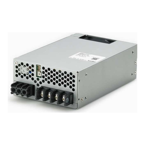
The C Series are flexible multi-output power supplies that enable
simple combination of various modules.
Features and Benefits
• High reliability with low noise and low leakage current
• Medical and information equipment approval to
UL60950-1, C-UL, EN60950 and EN60601-1 3rd
• Direct PFC with interleaving and AC synchronized rectification
• Higher withstand voltage and lower leakage current
• OCP, OVP and OHP, remote sensing, control, and alarm (AC
power fail, fan alarm, and low output)
Downloaded from Arrow.com.Downloaded from Arrow.com.Downloaded from Arrow.com.Downloaded from Arrow.com.Downloaded from Arrow.com.Downloaded from Arrow.com.Downloaded from Arrow.com.Downloaded from Arrow.com.
9
SANKEN ELECTRIC CO., LTD. December 2016PAN40004-001E-02
Names of Product Parts
Base Power Unit – Rear View
Base Power Unit
Base Power Unit
DC Modules
Installed
DC modules
Bus bar for parallel operation
(Bundled with C130x24 and C130x36)
Output terminal (TB2)
Signal input/output terminal (CN2)
Output voltage adjusters
LED status connector
GND common slots
(C300, C450, and C650)
GND common slot (C300 and C450)
Isolated slot (C650 only)
Slot 1
Slot 5
Slot 2
Slot 3
Slot 4
AUX - Signal output terminal (CN1)
Input terminals (TB1)
Neutral
Live
FG
Base Power Unit – Front View (with DC modules installed)
Downloaded from Arrow.com.Downloaded from Arrow.com.Downloaded from Arrow.com.Downloaded from Arrow.com.Downloaded from Arrow.com.Downloaded from Arrow.com.Downloaded from Arrow.com.Downloaded from Arrow.com.Downloaded from Arrow.com.

10
SANKEN ELECTRIC CO., LTD. December 2016PAN40004-001E-02
DC Module – Simplified View
Base Power Unit
DC Module
Connector to base power unit
Signal input/output terminal (CN2)
Output voltage adjuster
LED operation display
Output terminal (TB2)
Mounting tab
C
Series identifier, for C series
Nominal total rated output wattage, at 200 V
nominal system input (200 to 240 VAC)
[NNN]
[A]
Output mode
S: Single output
X: Corresponding to parallel drive
Nominal total rated output voltage, according to table:
[NN]
Symbol
03 3.3
05 5
12 12
15 15
24 24
Voltage
(V)
C
Series identifier, for C series
Nominal total rated output wattage
[NNN]
Model Number Description
Downloaded from Arrow.com.Downloaded from Arrow.com.Downloaded from Arrow.com.Downloaded from Arrow.com.Downloaded from Arrow.com.Downloaded from Arrow.com.Downloaded from Arrow.com.Downloaded from Arrow.com.Downloaded from Arrow.com.Downloaded from Arrow.com.

11
SANKEN ELECTRIC CO., LTD. December 2016PAN40004-001E-02
Input and Output Terminals, Connectors, and Pin Assignments
Base power unit terminals, connectors, and pin assignments
C300, C450 and C650 Power Inputs
Identification
Symbol Connector
Model Pin Assignments
Pin Number Name Note
TB1
UF2028AX
(Fujicon)
1 AC (Live) AC input
2 AC (Neutral) AC input
3 FG FG connection
Screws
Size Recommended Fastening Torque
M4 1.2 N•m (12.3 kgf•cm)
C300, C450 Auxiliary Terminals
Identification
Symbol Connector
Model Pin Assignments
Pin Number Name Note
CN1
S3B-XH-A
(JST)
1 GND Auxiliary output GND
2PR
Alarm signal; active high at
alarm operation
3 AUX Auxiliary output; for remote
on / off
Housing
XHP-3
(JST) Housing
SXH-001T-P0.6
(JST) Contact
TB1
1
2
3
L
N
1 2 3
CN1
Downloaded from Arrow.com.Downloaded from Arrow.com.Downloaded from Arrow.com.Downloaded from Arrow.com.Downloaded from Arrow.com.Downloaded from Arrow.com.Downloaded from Arrow.com.Downloaded from Arrow.com.Downloaded from Arrow.com.Downloaded from Arrow.com.Downloaded from Arrow.com.

12
SANKEN ELECTRIC CO., LTD. December 2016PAN40004-001E-02
C650 Auxiliary Terminals
Identification
Symbol Connector
Model Pin Assignments
Pin Number Name Note
CN1
S5B-XH-A
(JST)
1 AUX1 Auxiliary output1; for remote
on / off of GND common slots
2 GND1 Auxiliary output GND 1
3PR Alarm signal; active high at
alarm operation
4 GND2 Auxiliary output GND 2
5 AUX2 Auxiliary output 2; for isolated
slot
Housing
XHP-5
(JST) Housing
SXH-001T-P0.6
(JST) Contact
TB1
1
2
3
L
N
1...5
CN1
Downloaded from Arrow.com.Downloaded from Arrow.com.Downloaded from Arrow.com.Downloaded from Arrow.com.Downloaded from Arrow.com.Downloaded from Arrow.com.Downloaded from Arrow.com.Downloaded from Arrow.com.Downloaded from Arrow.com.Downloaded from Arrow.com.Downloaded from Arrow.com.Downloaded from Arrow.com.

13
SANKEN ELECTRIC CO., LTD. December 2016PAN40004-001E-02
DC module terminals, connectors, and pin assignments
Single output DC modules
Single Output DC Module Power Terminals
Identification
Symbol Connector
Model Pin Assignments
Pin Number Name Note
TB2
UF2028AX
(Fujicon)
1 +Vo Output voltage (+)
2 –Vo Output voltage (–)
Screws
Size Recommended Fastening Torque
M4 1.2 N•m (12.3 kgf•cm)
Single Output DC Module Signal Terminals
Identification
Symbol Connector
Model Pin Assignments
Pin Number Name Note
CN2
S8B-PHDSS
(JST)
1 +Remote On/Off Remote on/off
2 –Remote On/Off Remote on/off (GND)
3+M Remote sensing auxiliary
terminal 1 (Only for C150S)
4–M Remote sensing auxiliary
terminal 2 (Only for C150S)
5 LV-Alarm+ LV alarm output
6 LV-Alarm– LV alarm output (GND)
7 +Remote Sense Remote sensing, Vo side
(Only for C150S)
8 –Remote Sense Remote sensing, GND side
(Only for C150S)
Housing
PHDR-08VS
(JST) Housing
SPHD-001T-P0.5
SPHD-002T-P0.5
(JST)
Contact
CN2 Enlargement
1
3
5
7
2
4
6
8
CN2
VR1
Vo Adjust
+Vo
–Vo
Downloaded from Arrow.com.Downloaded from Arrow.com.Downloaded from Arrow.com.Downloaded from Arrow.com.Downloaded from Arrow.com.Downloaded from Arrow.com.Downloaded from Arrow.com.Downloaded from Arrow.com.Downloaded from Arrow.com.Downloaded from Arrow.com.Downloaded from Arrow.com.Downloaded from Arrow.com.Downloaded from Arrow.com.

14
SANKEN ELECTRIC CO., LTD. December 2016PAN40004-001E-02
Downloaded from Arrow.com.Downloaded from Arrow.com.Downloaded from Arrow.com.Downloaded from Arrow.com.Downloaded from Arrow.com.Downloaded from Arrow.com.Downloaded from Arrow.com.Downloaded from Arrow.com.Downloaded from Arrow.com.Downloaded from Arrow.com.Downloaded from Arrow.com.Downloaded from Arrow.com.Downloaded from Arrow.com.Downloaded from Arrow.com.

15
SANKEN ELECTRIC CO., LTD. December 2016PAN40004-001E-02
Block Diagrams
Noise filter PFC
FAN
Auxiliary power
supply
Slot 1
Slot 2
Slot 3
Slot 4
Slot 5
(Isolated)
AUX1 12V
SELV
DC21V DC module
DC module
DC module
DC module
DC module
Isolated
converter
AUX2 12V
(Isolated)
85 to 264 VAC
650 W C-series power supply
Noise filter PFC Isolated
converter
FAN
Auxiliary power
supply
Slot 1
Slot 2
Slot 3
Slot 4
Slot 5
AUX 12V
SELV
DC21V
C-series power supply
DC module
DC module
DC module
DC module
DC module
85 to 264 VAC
450 W C-series power supply
85 to 264 VAC Noise filter PFC Isolated
converter
FAN
Auxiliary power
supply
Slot 1
Slot 2
Slot 3
Slot 4
AUX 12V
SELV
DC21V
C-series power supply
DC module
DC module
DC module
DC module
300 W C-series power supply
C300 series
C450 series
C650 series
Downloaded from Arrow.com.Downloaded from Arrow.com.Downloaded from Arrow.com.Downloaded from Arrow.com.Downloaded from Arrow.com.Downloaded from Arrow.com.Downloaded from Arrow.com.Downloaded from Arrow.com.Downloaded from Arrow.com.Downloaded from Arrow.com.Downloaded from Arrow.com.Downloaded from Arrow.com.Downloaded from Arrow.com.Downloaded from Arrow.com.Downloaded from Arrow.com.

16
SANKEN ELECTRIC CO., LTD. December 2016PAN40004-001E-02
Parallel Operation
DC modules capable of parallel operation are available as the
C130X24 C130X36 model. Be sure to pay attention to
following notes when operating in parallel using the DC
modules.
1. When using the DC modules with adjusted output voltage, all
DC modules to be connected in parallel must be adjusted inde-
pendently. When adjusting using the output adjuster, ensure there
are no bus bars bridging between different DC modules before
rotating the output adjuster. Upon completion of adjustment of
the output voltage, then please install the bus bars.
2. When connecting the output terminals, be sure to connect only
terminals with the same electrical polarity characteristics to the
same bus bar.
3. When installing DC modules in parallel operation configu-
ration in a base power unit, be sure to use only slots that are
designed for parallel operation in the base power unit, as per the
following table:
Slots corresponding to parallel operation
C300 C450 C650
Slot 1 ○○○
Slot 2 ○○○
Slot 3 ○○○
Slot 4 ○○○
Slot 5 ○×
○: Compatible with parallel operation
×: Not compatible with parallel operation
4. When using the products with a dynamic load, be sure to apply
full evaluation and testing in the application before using.
CAUTION: The products are not compatible
with series operation. Be sure not to use the
products in a series configuration.
Functional Description
Downloaded from Arrow.com.Downloaded from Arrow.com.Downloaded from Arrow.com.Downloaded from Arrow.com.Downloaded from Arrow.com.Downloaded from Arrow.com.Downloaded from Arrow.com.Downloaded from Arrow.com.Downloaded from Arrow.com.Downloaded from Arrow.com.Downloaded from Arrow.com.Downloaded from Arrow.com.Downloaded from Arrow.com.Downloaded from Arrow.com.Downloaded from Arrow.com.Downloaded from Arrow.com.

17
SANKEN ELECTRIC CO., LTD. December 2016PAN40004-001E-02
Input Voltage Range, Harmonic Current, and
Inrush Current
Input voltage range
The input voltage range of a base power unit is 85 to 264 VAC.
If other than specified input voltages are applied, it could cause
the products to fail to operate within the specifications and/or
cause permanent failure of the products.
Harmonic current
A harmonic current suppression circuit (active filter) is incorpo-
rated into each base power unit, and harmonic current is sup-
pressed in all load conditions from no load to full load. The input
voltage range at which the harmonic current suppression circuit
activates is between 85 and 264 VAC.
Inrush current
If a switch is used for controlling input, be sure to select a switch
that can withstand the expected inrush current. If the AC sup-
ply is being switched off and on again, before reapplying power
wait until the internal cooling fan has stopped moving, otherwise
a large current could flow after release of the inrush preventive
circuit.
Protection Functions
Overcurrent protection (OCP)
Each DC module has an isolated overcurrent protection circuit
incorporated into it. When OCP is activated, it shuts down the
respective DC module. If output is stopped due to an overcurrent
condition, be sure to evaluate the load condition and remove the
causes of overcurrent before reapply AC either by remote on/off
or by input of the base power unit.
!
CAUTION: OCP does not necessarily
guarantee complete protection against any
short in the output circuit. Be sure not to short
the output when using the products.
!CAUTION: Regardless of the OCP range, be
sure not to exceed total rated output current
range or rated output power of the products.
Overvoltage protection (OVP)
Each DC module has an isolated overvoltage protection circuit
incorporated into it. When OVP is activated, it shuts down all
output. If output is stopped due to an overvoltage condition, be
sure to shut off the input and delay reapplying the AC supply
until more than 30 seconds after removal of the causes of the
overvoltage condition.
Thermal shutdown protection
Each base power unit has a thermal shutdown protection circuit
incorporated. The circuit is activated when the following abnor-
malities occur:
• When the airflow volume of the internal fan is lowered and/or
stopped, the internal temperature rises.
• When the base poser unit is used for a long time in conditions
exceeding the total rated power.
• When the base power unit is used in an ambient temperature
exceeding specified temperature in the specifications.
When thermal shutdown is activated, it shuts down all output.
Be sure to shut off the AC supply and remove the causes of the
overheating, as well as delay long enough for the products to cool
to normal temperatures, before reapplying the AC supply. If the
application requires that the product be used continuously, be
sure to apply thorough investigation of the causes and counter-
measures for overheating before using the product.
Downloaded from Arrow.com.Downloaded from Arrow.com.Downloaded from Arrow.com.Downloaded from Arrow.com.Downloaded from Arrow.com.Downloaded from Arrow.com.Downloaded from Arrow.com.Downloaded from Arrow.com.Downloaded from Arrow.com.Downloaded from Arrow.com.Downloaded from Arrow.com.Downloaded from Arrow.com.Downloaded from Arrow.com.Downloaded from Arrow.com.Downloaded from Arrow.com.Downloaded from Arrow.com.Downloaded from Arrow.com.

18
SANKEN ELECTRIC CO., LTD. December 2016PAN40004-001E-02
PR
GND
(Open collector)
Base power unit
CN1
LV Alarm +
LV Alarm –
(GND)
(Open collector)
DC module
CN2
PR terminal internal circuit LV-Alarm terminal internal circuit
Alarm Specifications
Alarm
Signal Operating
Condition Alarm Signal State
PR Good Set low (≤0.8 V and ≤8 mA)
Bad Set high (2 to 35 V, or open)
LV Good Set low (≤0.8 V and ≤20 mA)
Bad Set high (2 to 35 V, or open)
Alarm Functions
PR signal
This alarm is incorporated into each base power unit. The PR
terminal is set high when input voltage into the main body of the
base power unit is lowered below specification and/or the internal
fan is stopped.
LV-Alarm signal
This alarm is incorporated into each DC module. The LV-Alarm+
terminal is set high when the output of the DC module is lowered
below specification and/or is stopped.
Downloaded from Arrow.com.Downloaded from Arrow.com.Downloaded from Arrow.com.Downloaded from Arrow.com.Downloaded from Arrow.com.Downloaded from Arrow.com.Downloaded from Arrow.com.Downloaded from Arrow.com.Downloaded from Arrow.com.Downloaded from Arrow.com.Downloaded from Arrow.com.Downloaded from Arrow.com.Downloaded from Arrow.com.Downloaded from Arrow.com.Downloaded from Arrow.com.Downloaded from Arrow.com.Downloaded from Arrow.com.Downloaded from Arrow.com.

19
SANKEN ELECTRIC CO., LTD. December 2016PAN40004-001E-02
Alarm Timing Diagram
Input voltage
+Remote Sense
Signal
+Remote On/Off
signal
DC module
output voltage
2 to 35 V or Open
2 to 35 V or Open
≤
0.8 V and ≤
20 mA
≤
0.8 V and ≤
20 mA
LV-Alarm+
signal
Fan rotational
speed
AUX
Downloaded from Arrow.com.Downloaded from Arrow.com.Downloaded from Arrow.com.Downloaded from Arrow.com.Downloaded from Arrow.com.Downloaded from Arrow.com.Downloaded from Arrow.com.Downloaded from Arrow.com.Downloaded from Arrow.com.Downloaded from Arrow.com.Downloaded from Arrow.com.Downloaded from Arrow.com.Downloaded from Arrow.com.Downloaded from Arrow.com.Downloaded from Arrow.com.Downloaded from Arrow.com.Downloaded from Arrow.com.Downloaded from Arrow.com.Downloaded from Arrow.com.

20
SANKEN ELECTRIC CO., LTD. December 2016PAN40004-001E-02
Output voltage adjustable range and remote
sensing
Output voltage adjustable range
Each DC module has either one or two output voltage adjusters.
Rotate the adjuster clockwise to increase the output voltage and
counterclockwise to decrease the output voltage. When adjusting
the output voltage, be sure not to exceed either the rated output
power of the system, or the rated output current of the module.
The output voltage adjustable range varies for each DC module.
Please ascertain the specification of each DC module before
using.
Remote sensing
Some DC modules incorporate remote sensing function. Remote
sensing functions allow the system to compensate for voltage
reduction due to output wiring. The range of voltage compensa-
tion available varies according to DC module, as shown in the
table at right.
When using remote sensing, be sure to conduct a thorough evalu-
ation and adjustment of the application system, based on the
remote sensing connection example shown.
Be sure to pay attention to following notes when using the remote
sensing function:
• Be sure to use thick wire, with a sufficient current capacity
margin above the maximum output current for wiring from power
supply to the load. Set the line drop to the compensated voltage or
below.
• Oscillating waveforms and/or fluctuations of output voltage
could arise due to wiring and load impedance. Be sure to apply a
thorough evaluation before using the products.
!
CAUTION: When a bad connection (for
example, caused by a loose screw) of a
load wire arises, the load current flows
into the remote sensing wire and it could
cause damage to the power supply due to
overheating. Be sure to pay attention when
connecting wires.
Remote Sensing Voltage Compensation
DC Module Type Voltage Compensation Range
C150S03, C150S05,
C150S12, C150S15
0.15 V and below
C150S24 0.30 V and below
NOTE: Any DC module not listed in this table is not compatible
with remote sensing.
+Vo
–Vo
+M
–M
+Remote Sense
DC module (remote
sensing compatible)
–Remote Sense
Load
Remote sensing connection example
Downloaded from Arrow.com.Downloaded from Arrow.com.Downloaded from Arrow.com.Downloaded from Arrow.com.Downloaded from Arrow.com.Downloaded from Arrow.com.Downloaded from Arrow.com.Downloaded from Arrow.com.Downloaded from Arrow.com.Downloaded from Arrow.com.Downloaded from Arrow.com.Downloaded from Arrow.com.Downloaded from Arrow.com.Downloaded from Arrow.com.Downloaded from Arrow.com.Downloaded from Arrow.com.Downloaded from Arrow.com.Downloaded from Arrow.com.Downloaded from Arrow.com.Downloaded from Arrow.com.
This manual suits for next models
3
Table of contents
Other Sanken Power Supply manuals
Popular Power Supply manuals by other brands

KEPCO
KEPCO JQE 25-20MVPY-27274 instruction manual

Tripp Lite
Tripp Lite Extended-Run Single-Phase Battery Cabinet owner's manual

KEPCO
KEPCO BOP-H Series Operator's manual

Corsair
Corsair VX550W user manual

Delta
Delta LZ-16/POL/R19 user manual

AutomationDirect
AutomationDirect Rhino PSB12-015-P installation instructions