This manual suits for next models
3
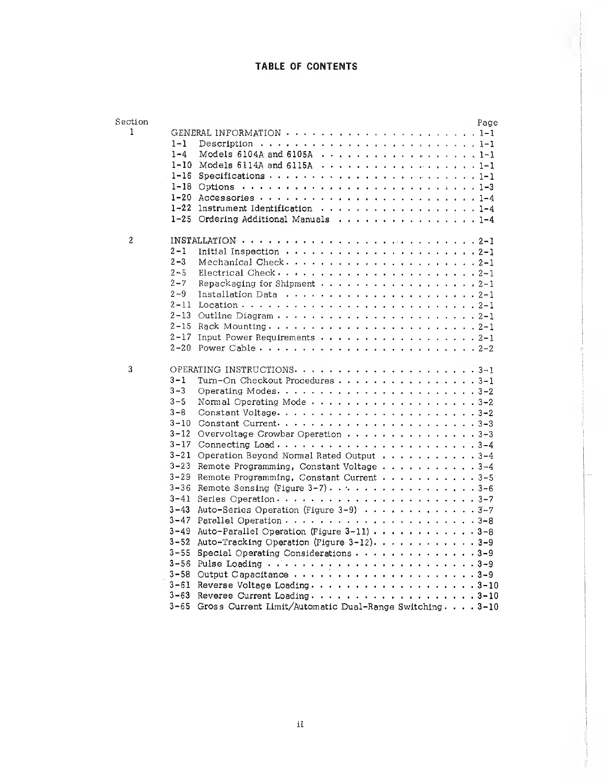
Table of contents
Other HP Power Supply manuals
HP
HP 6960A Service manual
HP 6034A User manual
HP 712B Owner's manual
HP 66312A Operating instructions
HP 6269B Installation instructions
HP StorageWorks SN6000 User manual
HP StorageWorks 1000 - Modular Smart Array Operating instructions
HP BENCH Series Service manual
HP 6236B Service manual
HP 6236A Service manual
HP D7171A - NetServer - LPr Installation and operation manual
HP PSR1800-56A User manual
HP 711A Service manual
HP 6200B Service manual
HP HVB Series User manual
HP 6296A Service manual
HP 59501B Service manual
HP E3633A User manual
HP 710B Parts list manual
HP PSR750-A User manual
HP UPS R/T3000 User manual
HP UPS User manual
HP PSR650-A User manual
HP J9405B Assembly instructions
Monacor
Monacor PS-12CCD instruction manual
VOLTIMA
VOLTIMA MagicBox 15 Installation and operating instructions
Miller
Miller Auto Deltaweld 452 owner's manual
BCP
BCP PUOUBK How to install
HC
HC 2210 manual
Agilent Technologies
Agilent Technologies 6032A Service manual
Puls
Puls CT5.241 installation manual
OCZ
OCZ ZX1250W Technical specifications
iseg
iseg ECH 238 manual
Agilent Technologies 6631B Service manual
Power
Power XXL A Series instruction manual
Renogy
Renogy PHOENIX 300 user guide
Epson
Epson Stylus Scan 2500 Product information sheet
Pulsar
Pulsar GREEN POWER CCTV PoE POE044816 manual
Puls MiniLine ML50.100 instruction manual
Puls AS-Interface SLA4.100 installation manual
Kenwood
Kenwood PS-60 instruction manual
Elmdene
Elmdene G1380xN-y-s Series manual