SANKO SK-2200 User manual

NEEDLE & IRON PIECE DETECTOR
SK−2200
(WIDE SPAN TYPE)
INSTRUCTION MANUAL
CAUTION
●Before using the Detector, read this INSTRUCTION MANUAL thoroughly
for correct use.
● Keep this INSTRUCTION MANUAL carefully and refer to it when necessary.
● In the event of any doubt arising, the original INSTRUCTION MANUAL in
Japanese is to be final authority.
Office: Jl. Radin Inten II No. 62 Duren Sawit, Jakarta 13440 - Indonesia
Workshop: Jl. Pahlawan Revolusi No. 22B, Jakarta 13430 - Indonesia
Phone: 021-8690 6777 (Hunting) Fax: 021-8690 6777
Mobile: +62 816 1740 8925
Fax: 021-8690 6771

CONTENTS
ITEM PAGE
CAUTIONS IN OPERATION 2
1.OUTLINE 3
2.PRINCIPLE 3
3.FEATURES 3
4.APPLICATIONS 3
5.SPECIFICATIONS 4
6.NAME OF PARTS AND FUNCTIONS 5
6‑1 Main body (Front view) 5
6‑2 Main body (Rear view) 6
6‑3 Probe 8
7.SPECIFICATIONS OF MULTI-CHANNEL SYSTEM 9
8.INSTALLATION 10
8‑1 Power source 10
8‑2 Frame 10
8‑3 Installing position of the probe 10
8‑4 Installing position of the probe cable and the main body 11
8‑5 Accessories & sub-materials 11
8‑6 Adjusting the sensitivity 11
9.OPERATING INSTRUCTIONS 12
9‑1 Operating method Ⅰ13
9‑2 Operating method Ⅱ15
Office: Jl. Radin Inten II No. 62 Duren Sawit, Jakarta 13440 - Indonesia
Workshop: Jl. Pahlawan Revolusi No. 22B, Jakarta 13430 - Indonesia
Phone: 021-8690 6777 (Hunting) Fax: 021-8690 6777
Mobile: +62 816 1740 8925
Fax: 021-8690 6771

-2-
CAUTIONS IN OPERATION
● Before using the Detector, read this INSTRUCTION MANUAL thoroughly for correct and
safety use.
● Keep this INSTRUCTION MANUAL carefully and refer to it when necessary.
● The Detector helps to simplify and to raise efficiency of detecting/inspecting work of
iron needles and broken needles straying in sewn garments.
● To remove straying needles, parallel uses with other various methods are recommended.
● The Detector is an iron piece detector for detecting iron pieces which stick to a
magnet. Nonferrous materials such as stainless steel, brass, aluminum and so on which
do not stick to a magnet can not be detected.
However, certain mass or size of material will react to the Detector occasionally.
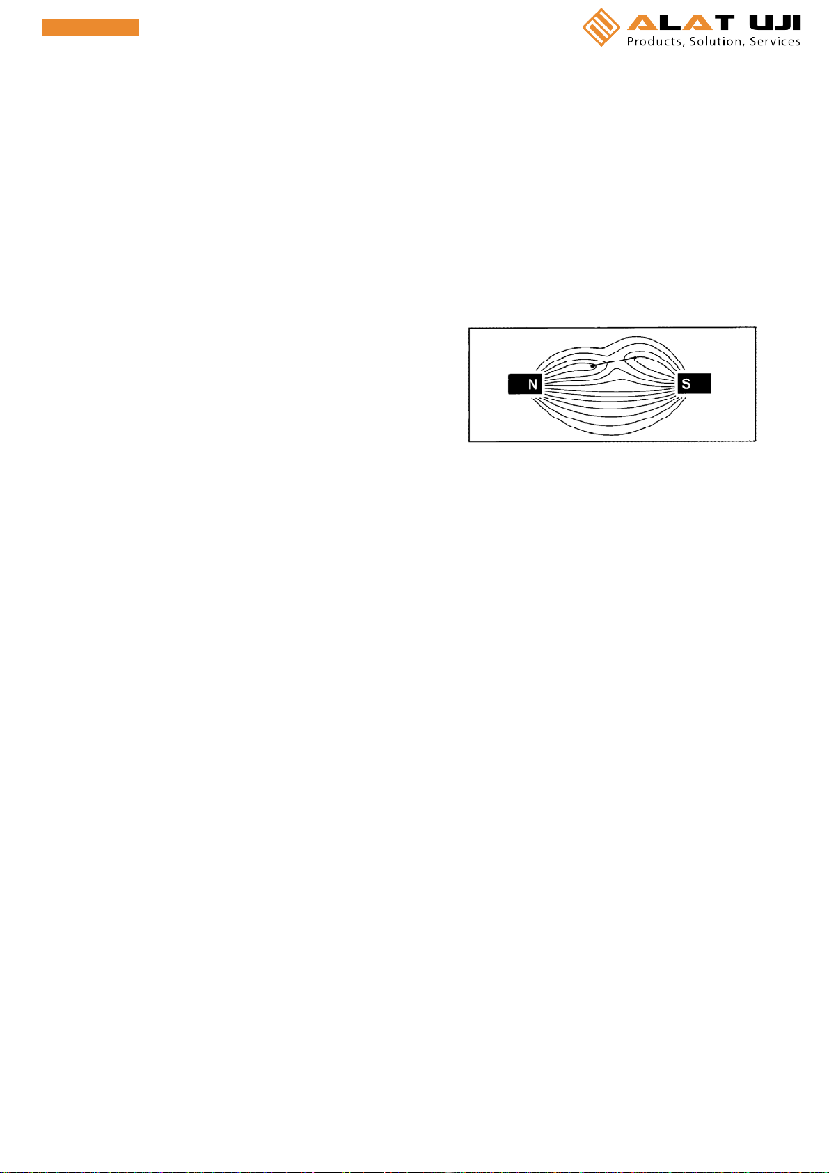
● The probe emits strong magnet force.
Be sure to keep the following items away from the probe, otherwise these items may
become out of order occasionally.
Magnetic card such as cash card, credit card, commuter pass and so on. Floppy disc.
Precision instrument such as wristwatch and so on.
● Be sure to confirm the detecting ability before commencing the needle detecting work.
●Detecting ability is influenced by the quality, size, speed, and directionofthe
needles or iron pieces to be detected.
Confirm with the sample to be detected in the same height and speed as the actual
operating condition.
●Generally, there are tendencies for detecting needles or iron pieces as follows;
【Quality】 Mild steel is easier to be detected.
Nearer to steel, harder to be detected.
【Size】 Larger in size, easier to be detected.
【Speed】 Generally, faster in speed, easier to be detected.
When the production line can not be increased speed, please contact us.
【Direction】 It depends on the shape of iron pieces.
Detecting ability of a long, slender object such as needles differs
from the direction, lengthwise or sideways.
● Be sure to use needles made of iron.
There are some marking pins, pins and so on made of stainless or brass which do not
stick to a magnet. These materials can not be detected.
● The using methods deviating from the efficiency and the function of the Meter and
remodeling are beyond the control of the manufacturer, so that the manufacturer can not
accept responsibility for any loss resulting from above mentioned uses and remodeling.

-3-
1.OUTLINE
SANKO NEEDLE & IRON PIECE DETECTOR SK-2200 is the Detector for detecting iron needles,
nails and broken pieces etc. straying in various kinds of textile products and industrial products
by means of the ultrahigh sensitive sensor and the circuit assembled.
Iron pieces and needles straying in textile, fabric roll, carpet, felt, non-woven fabric, etc.
which are very difficult to examine with the table type detector SK-1200 series, can be detected
with this Detector high sensitively and efficiently.
In process detecting(needle detecting) work is also available with this Detector installed in production
lines.
2.PRINCIPLE
When a magnetic substance such as iron piece, needle,
etc. moves in magnetic field which is made by a coil
built-in permanent magnet, a little electric current
flows in the coil.
This electric current is amplified up to the level in
order to operate the alarm function circuit e.g. buzzer,
lamp, output relay and advise us the existence of substances.
3.FEATURES
①High sensitivity and reliability allow us to detect even a small needle and iron piece.
②As the high reliable dust proof parts and elements are adopted in inner circuit, the Detector is
available to use in dust full factories and workshops for a long period.
③As detecting width is applicable to wide range from 560 mm up to 2.000 mm (based on 560 mm
by 72 mm pitch), the Detector is available to use for wide carpet, textile, fabric roll, etc.
④As the Detector normally equipped with the no-voltage contact output, it is available to control
lines and marking apparatus, also.
4.APPLICATIONS
①Needle detecting work for needles, broken needles and iron pieces straying in wide objects
e.g. textile, carpet, futon, blanket, felt, non-woven fabric, fabric roll, etc. with the installed Detector
in a production line.
②Detection of iron pieces straying in foods, packed foods, pharmaceutical packages, etc.
③Needle detecting work for needles and broken needles straying in large-sized sewn products e.g.
long dress, coat, etc. with the buried Detector into working tables and roll inspecting tables.

-4-
5.SPECIFICATIONS
●Model Needle & Iron Piece Detector SK-2200
●Method Magnetic induction
●Alarm device Electronic buzzer, LED lamp
●Alarm output No-voltage contact output (With hold reset function)
Contact capacity AC 250V, DC 125V, 5A (Peak value)
●Detectable object Iron needles and iron pieces straying in sewn products and textile etc.
●Detecting ability Max. 50 to 60 mm above detecting surface against an iron set pin
(Needle detection) Max.10mm against φ0.3 × L2 mm
Depends on quality, size and moving speed of iron piece.
(Optimum speed: 30 to 50m/min)
●Power source AC 100V to 240V 50/60 Hz
●Power consumption 10W
●Dimensions & Weight Main body:
1ch, 2ch 280 (W) × 110 (H) × 230 (D) mm Approx. 3 kg
3ch and more 350 (W) × 110 (H) × 260 (D) mm Approx. 5 kg
(excluding appendix)
Probe: 100(W) × 91(H) × 810 to 2250(L)mm 6 to 24 kg
※Size and weight of the probe vary with the detecting width.

-5-
6.NAME OF PARTS AND FUNCTIONS
6‑1 Main body (Front view)
①Power source lamp
・Thelampwillgoonwhenthepowersourceswitch②ON.
・The lamp will go on with red color until the circuit become stable for 5 to 7 seconds.
After that the color changes to green to advise us ready for detecting.
The Detector can not be used while the lamp is going on with red color.
※The instant the power source switch ②ON, alarm lamp ⑥, alarm buzzer ⑫, no-voltage contact
output will work.
To prevent and cut these works, the power source lamp ①goes on with red color until the circuit
become stable, so that the needles etc. can not be detected while the lamp is going on with red color.
It is because the outside line is not influenced by the power source switch ON of the Detector after
starting the outside line at first for the assembled Detector in line.
②Power source switch (POWER)
・When the power source switch ON, the power source lamp ①goesonwithredcolorfirstand
changes to green color to become ready for detecting.
③Sensitivity adjusting dial (SENS LEVEL)
・The dial is for adjusting the detecting sensitivity. The sensitivity will increase by turning the dial
to the right (clockwise), and it will decrease by turning to the left (counterclockwise).
Usually, the Detector is used at the right end of the dial where is the highest sensitivity.
(The figure in the small window is 10, and the graduation on the dial is 0.)
・When the Detector is influenced by surrounding noises, accessories and sub-materials, carefully adjust
the Detector noticing its detecting sensitivity.
・After completing the adjustment, lock the dial by lowering the lever fitted at the diagonal upper right
of the dial.
④Hold switch (HOLD)
・The switch converts ON/OFF of the no-voltage contact output, the alarm lamp ⑥and alarm
buzzer ⑫whether ON is continuously or momentarily. (In case the buzzer switch ⑪ON.)
[In case switch ON] When iron pieces are detected, no-voltage contact output, alarm lamp ⑥and
alarm buzzer ⑫continue ON state until pressing the reset button ⑤.
[In case switch OFF] When iron pieces are detected, no-voltage contact output, alarm lamp ⑥and alarm
buzzer ⑫will be ON momentarily, after that it will return to OFF automatically.
⑤Reset button (RESET)
・The button releases the no-voltage contact output, alarm lamp ⑥and alarm buzzer ⑫which has
been held ON state when iron pieces are detected by the hold switch ON.
⑥Alarm lamp (ALARM)
・The lamp will go on when iron pieces and/or needles are detected.
・The lamp will go on continuously or momentarily according to the setting condition of above
mentioned hold switch ④.

-6-
6‑2 Main body (Rear view)
⑦Receptacle of the probe connector (PROBE)
・The receptacle of the main body for connecting the cable connector ⑮with the probe cable.
⑧Output terminal (OUTPUT, RESET, GND)
・The terminal is for connecting the no-voltage contact output, reset, GND to outside.
・○
+symbol on the both ends of the terminal are screws for fitting the terminal.
・No 1,2 and 3 on the left side of the terminal are for the no-voltage contact output as
showninrightsketch.
No.1 is NC (Normally Close). Normally ON condition to No.2 COM
terminal excepting relay acting condition.
No.2 is COM (Common). The common terminal to No.1 and No.3.
No.3 is NO (Normally Open). Normally OFF condition to No.2 COM
terminal excepting relay acting condition.
・As the contact capacity of the relay is Max. AC 250V / DC 125V,
5A, use the Detector under these values.
・When an outside load is inductive one, prevent the generation of the noises
in the varistor, diode and Sunaba circuit etc.
・No.5 and No.6 are the terminal for operating the reset at a distance from the main body.
When use these terminals, remove the jumper fitting set in No.5 and No.6, and connect a 2-core
cord to the terminals and fit the switch etc. at the point of the cord.
The operating voltage of the circuit is 5V, use the switch having current capacity more than 1A.
The switch is a momentary type which returns original position by releasing the finger. Use the
COM and NC terminals which are normally ON position and become to OFF position by pressing.
When the jumper fitting is removed without using these terminals, the hold function can not be
operated even though the hold switch ④ON.
When the terminals are not used, be sure to set the jumper fittings.
・No.8 is the terminal for connecting the earth.

-7-
⑨Fuse holder (FUSE)
・The fuse holder containing the fuse (1A)
⑩Power source cord (POWER AC 100 to 240V)
・Connect the cord to the independent receptacle which differs a breaker to prevent the influence by
a power source noises.
⑪Buzzer switch
・ON-OFF switch for the alarm buzzer ⑫.
When the switch ON, the alarm buzzer operates linking with the alarm lamp ⑥.
When the switch OFF, the alarm lamp ⑥only operates but the alarm buzzer ⑫does not sound.
⑫Alarm buzzer
・When the buzzer switch ⑪ON, the sound of the buzzer advise us the existence of the needles or
iron pieces.

-8-
6‑3 Probe
Plan
Front View
⑬Probe
・Move the object to be examined crosswise to a length direction.
Iron pieces etc. can not be detected when the object is not moved.
(Refer to 2. PRINCIPLE on page 3.)
・The speeds 30 to 50m per minute are recommended. The detection in the speeds less than these
speeds is possible but the detecting sensitivity will become low.
⑭Probe cable
・The cord is for connecting the probe and the main body with a standard 3m in length.
・When the probe cable ⑭vibrates or sways, it causes malfunction.
・Install the probe closely to the instrument proper as possible to prevent the invasion of the noises
from the probe cable ⑭, but keep 1m distance each other.
・When the main body is installed at a distance from the probe, do not install the probe
cable ⑭parallel with the cables or the cords which generate noise. Moreover, avoid to
pass near the switch box generating sparks and fix the probe cable ⑭tightly.
⑮Cable connector
・Surely insert the cable connector ⑮in the receptacle ⑦on the rear of the main body and
the receptacle ⑯of the probe and firmly tighten the probe cable by turning the connector ring.
・When the cable connector ⑮is inserted insufficiently or the connector ring is not tightened firmly,
it causes malfunction due to outside noises. Be sure to tighten the connector ring.
⑯Receptacle of the probe
・The receptacle of the probe is for connecting the cable connector ⑮with the probe cable ⑭.
As the same with the main body, firmly tighten the cable connector by turning the
connector ring.
⑰Effective detectable range mark
・This is the mark showing the detectable range.
Set the inspection line so as to pass the objects to be measured within the marks on the both ends.

-9-
7.SPECIFICATIONS OF THE MULTI‑ CHANNEL SYSTEM
◎The detecting element in the probe is divided into 2 to 4 channels, and the removing time is shortened
by limiting the places where the detected needles or iron pieces are straying.
◎The alarm lamps ⑥of the main body indicate the detected places for each channel.
◎For the main body specified with the multi-channel system, the sensitivity adjusting dial ③,
the alarm lamp ⑥and the receptacle for the connector ⑦are increased the numbers equal to the
channel numbers.
For the probe ⑬, the receptacle ⑯and the probe cable ⑭are also increased same as above mentioned.
◎Even if some channels are not used in the Detector specified with the multi-channel system,
surely connect the probe cable ⑭to the channels not in use between the main body and the probes.
When all the probe cables ⑭are not connected, it causes a malfunction.
◎The main body specified with the multi-channel system and the probe is matching.
Connect the probe having the same number with the main body after confirming each number.
When the main body and the probe having the different numbers each other are connected,
notice that the Detector can not be obtained the original abilities and also it causes malfunction.
Front view of the main body (Example: Specified with 4 channels system)

-10-
8. INSTALLATION
SK-2200 is the Detector to detect iron pieces applying the principle of magnetic induction.
The Detector detects iron pieces which move relatively against the probe ⑬(sensor part) in
principle, so that it will react to iron-made objects nearby and work incorrectly when the probe ⑬
vibrates or swings itself. When metallic moving objects e.g. crankshaft, arm, etc. exist nearby the
probe, it causes malfunction also.
When the Detector is installed in surroundings having noises around, the Detector must be used under
lowered condition of its sensitivity more or less in order to cancel surrounding noises and noises
caused by the vibration of the probe.
To detect smaller iron pieces applying the original sensitivity of the Detector, please use the Detector
under the best condition of the system keeping minimize the lower of it sensitivity as possible
according to the following methods.
8‑1. Power source
Use the independent receptacle having exclusive breaker which is fitted in the exclusively
wired power source line to prevent noises from power source line.
8‑2. Frame
When the Detector is installed on iron or wooden frames, design these structures as rigid as
possible to reduce the vibration and the distortion of the structures totally.
8‑3. Installing position of the probe
Install the probe at the available places keeping distance as far as possible from metallic
moving equipment e.g. motor, conveyer's driving chain, guide roller, etc. and unstable and
easy-to-move iron column and frame etc.
When the Detector is installed at the place nearby metallic moving equipment due to insufficient
installing space, the following precautions should be taken.
●In case a rotating roller, motor and chain etc. exist close within 2m:
Confirm the effects of noises under provisionally installing condition of the probe ⑬before
installation.
Quantity of noises depends on diameter, rotating numbers (momentum), mass, quality, vibration,
etc., but usually the Detector is possible to be installed close up to about 50 cm.
(The sensitivity may be needed to lower occasionally.)
■The places where the Detector should not be installed:
・On unstable tables
・On top of steel desks
・On or beside iron columns and frames waving unstably
・Beside switches or relays generating spark noise
・Beside electric sewing machines
・Beside high frequency melting sealing machines
・Just beside generating sources of other noise e.g. electrical noise and mechanical noise.

-11-
8‑4. Installing position of the probe cable and the main body
Vibration and swinging of the probe cable ⑭cause malfunction.
The position of the probe and the main body is ideal that they are installed as close as
possible to protect them from invasion of the noise from the probe cable ⑭.
Note: Even if in this case, keep a distance more than 1m at least.
●When the main body is desired to be installed away from the probe:
・Firmly fix the probe cable ⑭not to swing.
・Do not band the probe cable ⑭parallel to cables or cords etc. generating noise.
And avoid to pass through around switch boxes generating sparks.
・The probe cable can be extended up to about 15m. In this case, pass the cable through
pipes firmly fixed.
・When the facility is newly designed, use brushless motors for driving motors of lines.
8‑5. Accessories and sub‑materials
When metallic accessories and sub-materials e.g. buttons, fasteners are fitted in an object
to be inspected, the Detector occasionally detect them as well as iron pieces and needles.
・Specify to use the buttons, fasteners and other parts indicated as "Detection support type"
at the design and planning stage for the accessories, sub-materials e.g. metallic buttons,
fasteners, etc.
8‑6. Adjusting the sensitivity
The Detector is in the highest sensitive condition at the pointing position [10] of the sensitivity
adjusting dial.
When using the Detector lowering its sensitivity to avoid effects of accessories, sub-materials
and surrounding noises, start the detecting (needle detection) work after confirming that the
Detector can detect the iron pieces and needles required to detect under lowered condition of
sensitivity.
■Noises which generate by the various causes mentioned above are added up and invade into
the circuit and cause malfunction.
Remove these factors as possible to use the Detector in its highest sensitive condition.

-12-
9.OPERATING INSTRUCTIONS
The Detector is provided with the no-voltage contact output function and hold・reset functions
built-in to control external lines.
◆No-voltage contact output
This no-voltage contact output signal converts the power source of the motor and the marker in
external lines to ON or OFF.
It is available to keep ON or OFF continuously or momentarily using with the hold・reset
functions together.
◆Hold・Reset function
《In case hold ON 》
When needles or iron pieces are detected, no-voltage output terminal will be kept
continuously ON or OFF. The alarm lamp ⑥keeps on continuously going on.
The Detector will be restored to original state by pressing the reset button ⑤.
《In case hold OFF 》
When needles or iron pieces are detected, no-voltage output will be ON or OFF
momentarily. The alarm lamp ⑥will go on momentarily also.
Two methods which are used without no-voltage contact output・hold function and with these
functions are explained as follows.

-13-
9‑1. Operating method Ⅰ
[In case the Detector is used without no‑voltage contact output・hold function]
Operations Cautions
1 Confirm both power source switch ②OFF and
hold switch ④OFF.
2 Following the previous item 8. INSTALLATION ・Connect the same numbered probe after
on page 10, correctly install the main body and confirming the number of the main body.
the probe.
Insert the cable connector ⑮in the receptacle ⑦
of the main body and the receptacle ⑯
of the probe and tighten it by turning the
connector ring.
3 Insert the power source cord ⑩into a receptacle ・Connection to a branch receptacle causes
within AC 100V to 240V. malfunction.
4 Power source switch ②ON. ・The alarm lamp ⑥will keep on going on under
・The power source lamp ①will go on and hold switch ④ON condition.
the color changes from red to green. Hold switch OFF and confirm the alarm lamp
・Confirm the buzzer switch ⑪ON. ⑥will go out.
・The alarm buzzer ⑫is gone for 2 to 3times, ・The Detector can detect nothing while the
and it is possible to detect. power source lamp ①is red color. Confirm
・
Confirm that the alarm lamp ⑥will go on the operation for detection after changing the
with buzzer sound. color from red to green.
The alarm buzzer ⑫does not work when the
buzzer switch ⑪OFF.
5 Turn the sensitivity adjusting dial ③to the ・When the sensitivity adjusting dial is at
right (clockwise) to set at level [10]. position〔0〕,the Detector can detect nothing.
6 Confirming the detecting ability
◆In case the probe is installed in line:
After running the line, confirm the detecting ・Objects to be inspected must be moved.
ability with the testing objects on which the
samples of breaking needles and iron pieces
desired to detect were stuck with tape etc.
When the surrounding noises cause ・Before turning the sensitivity adjusting dial
malfunction, turn the sensitivity adjusting ③, take noise sources away as possible.
dial ③to the left (counterclockwise) until Refer to 8, INSTALLATION on page 10.
malfunction stops.
After that, reconfirm the detecting ability
under running condition of the line.
◆In case the probe is built-in into the
inspection table etc.:
Confirm the detecting ability with the testing ・Objects to be inspected must be moved.
objects on which the samples of breaking
needles and iron pieces desired to detect were
stuckwithtapeetc.bymovingthoseacross
the detecting surface of the probe ⑬.

-14-
7 Commencing the detecting work.
・After confirming the detecting ability ・Objects to be inspected must be moved
according to previous item 6, operate the ・The alarm lamp ⑥will keep on going on under
Detector for detection (needle detection) hold switch ④ON condition.
moving the objects to be measured. Hold switch OFF and confirm the alarm lamp
◎Lock the sensitivity adjusting dial ③not to ⑥will go out.
move. ・More than one needle or iron piece might be
・When iron pieces and needles are straying in the object. Carry out the detecting
detected, the alarm lamp ⑥will blink with work again for the same place to confirm after
sound of the alarm buzzer ⑫. removing the detected one.
◎The alarm buzzer ⑫does not sound when the
buzzer switch ⑪OFF.
8 Completing the detecting work. ・When the Detector is not in use, surely pull the
Power source switch ②OFF power source plug out of the receptacle.

-15-
9‑2. Operating method Ⅱ
[In case the Detector is used with no‑voltage contact output・hold function.]
●The no-voltage contact output and hold reset function are used to hold the control of the outside
line ・marking・alarm lamp etc.
Operations Cautions
1 Confirm both power source switch ②OFF
and hold switch ④OFF.
2 Following the previous item 8. INSTALLATION ・Connect the same numbered probe after
on page 10, correctly install the main body confirming the number of the main body.
and the probe.
Insert the cable connector ⑮in the receptacle ⑦
of the main body and the receptacle ⑯of the
probe and tighten it by turning the connector
ring.
3 Insert the power source cord ⑩into a receptacle ・Connection to a branch receptacle causes
within AC 100V to 240V. malfunction.
4 Power source switch ②ON. ・The alarm lamp ⑥will keep on going on under
・The power source lamp ①will go on and hold switch ④ON condition.
the color changes from red to green. Hold switch OFF and confirm the alarm lamp
・Confirm the buzzer switch ⑪ON. ⑥will go out.
・The alarm buzzer ⑫is gone for 2 to 3times, ・The Detector can detect nothing while the
and it is possible to detect. power source lamp ①is red color. Confirm
・
Confirm that the alarm lamp ⑥will go on the operation for detection after changing the
with buzzer sound. color from red to green.
The alarm buzzer ⑫does not work when the
buzzer switch ⑪OFF.
5 Turn the sensitivity adjusting dial ③to the right ・When the sensitivity adjusting dial is at
(clockwise) to set at level [10]. position [0], the Detector can detect nothing.

6 Confirming the detecting ability
◆In case the probe is installed in line:
After running the line, confirm the detecting ・Objects to be inspected must be moved.
ability with the testing objects on which the
samples of breaking needles and iron pieces
desired to detect were stuck with tape etc.
When the surrounding noises cause ・Before turning the sensitivity adjusting dial ③,
malfunction, turn the sensitivity adjusting take noise sources away as possible.
dial ③to the left (counterclockwise) until (Refer to 8. INSTALLATION on page 10.)
malfunction stops.
After that, reconfirm the detecting ability
under running condition of the line.
◆In case the probe is built-in into the
inspection table etc.:
Confirm the detecting ability with the testing ・Objects to be inspected must be moved.
objects on which the samples of breaking
needles and iron pieces desired to detect were
stuck with tape etc. by moving those across
the detecting surface of the probe ⑬.
7 Hold switch ④ON. When the alarm lamp ⑥keeps on going on,
press the reset button ⑤and confirm the alarm
lamp ⑥goes out.
8 Commencing the detecting work.
・After confirming the detecting ability ・Objects to be inspected must be moved.
according to previous item 6, operate the
Detector for detection (needle detection)
moving the objects to be inspected.
◎Lock the sensitivity adjusting dial ③not to
move.
・When iron pieces and needles are detected, ・More than one needle or iron piece might be
the alarm lamp ⑥keeps on going on with straying in the object.
sounds of the alarm buzzer ⑫Carry out the detecting work again for the same
・After removing iron pieces and needles, place to confirm after removing the detected
release the alarm by pressing the reset button one.
⑤.
◎The alarm buzzer ⑫does not sound when the
buzzer switch ⑪OFF.
9 Completing the detecting work. ・When the Detector is not in use, surely pull the
Power source switch ②OFF. power source plug out of the receptacle.
Office: Jl. Radin Inten II No. 62 Duren Sawit, Jakarta 13440 - Indonesia
Workshop: Jl. Pahlawan Revolusi No. 22B, Jakarta 13430 - Indonesia
Phone: 021-8690 6777 (Hunting) Fax: 021-8690 6777
Mobile: +62 816 1740 8925
Fax: 021-8690 6771
Table of contents