Failure to use specified installa�on parts or hardware will void
the product warranty.
For this product to operate at op�mum efficiency ,a good
electrical connec�on to chassis ground must be made.
It is recommended that these instruc�ons be stored in a safe
place and referred to when performing maintenance or
reinstalla�on of this product.
Do not install and/or operate this safety product unless you
have read and understand the safety informa�on contained in
this manual.
It is the responsibility of the vehicle operator to ensure during
use that all features of this product work correctly. In use, the
vehicle operator should ensure the projec�on of the warning
signal is not blocked by vehicle component,people, vehicles,or
other obstruc�ons.
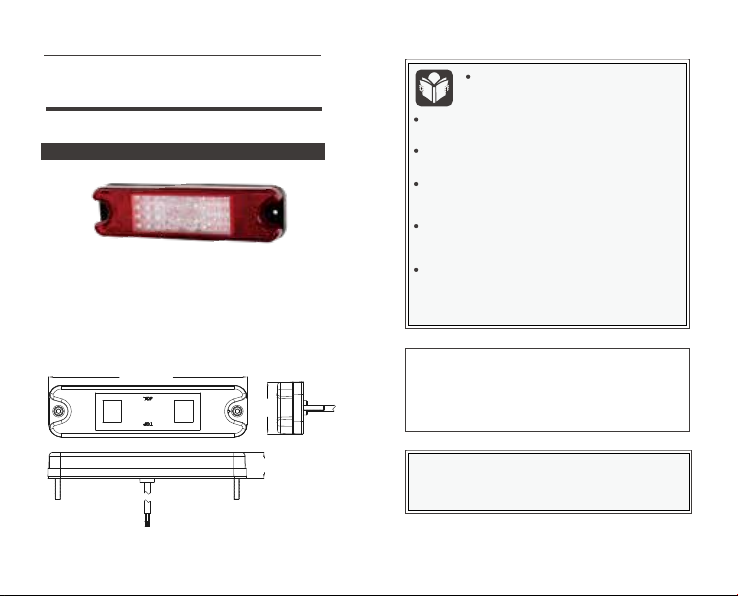
Specifica�ons
OPERATION INSTRUCTION
Proper installa�on of this product requires the
installer to have a good understanding of
automo�ve electronics,systems and procedures.
8106A
This document provides all the necessary informa�on to
allow your product to be properly and safely installed. Before
beginning the installa�on and opera�on of your new product,
the installa�on technician and operator must read this
manual completely.
Important! This unit is a safety device, and it must be
connected to its own separate, fused power point to assure its
con�nued opera�on should any other electrical accessory fail.
• Voltage: 10-80V
• IP Ra�ng: IP67
• Max Power: Stop 3w, DI 3W, Tail 1.5, Reverse 2w
• Moun�ng: Surface mount
• Func�ons : Stop / Tail / Direc�on indicator / Reverse / Reflex
24.5mm
191mm
50mm
LED Lighthead


