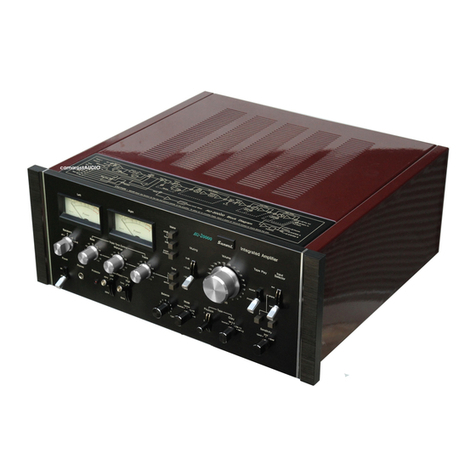
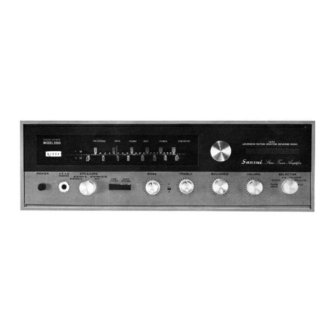
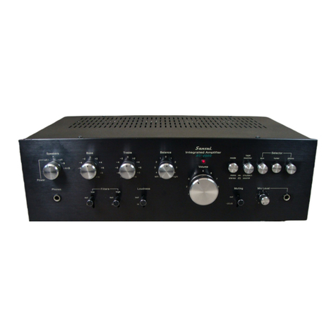
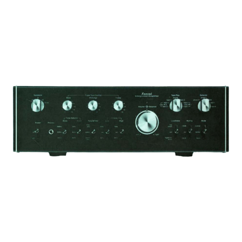
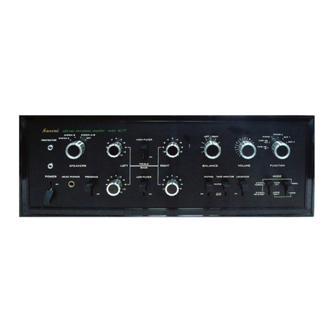
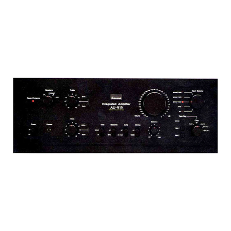
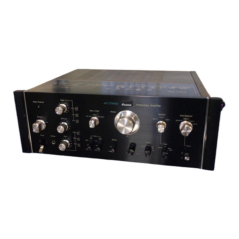
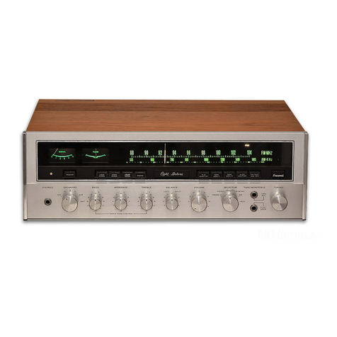
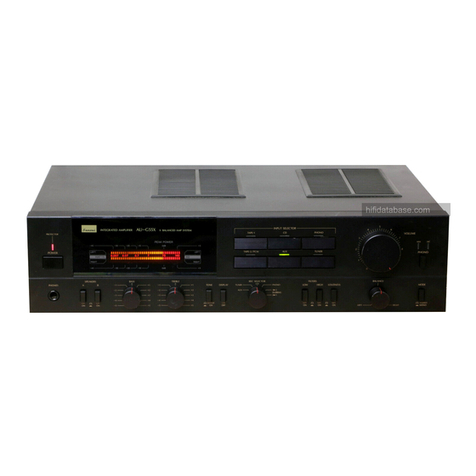
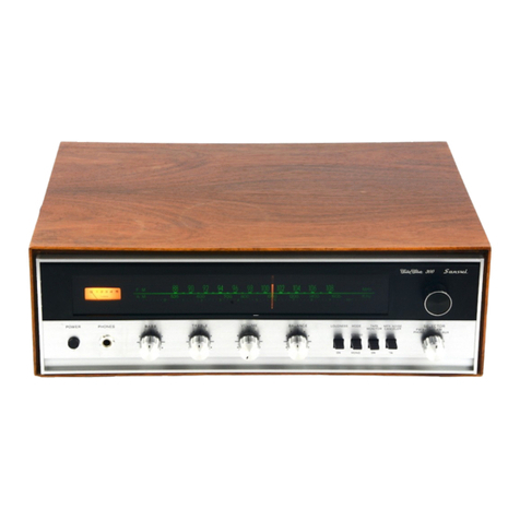
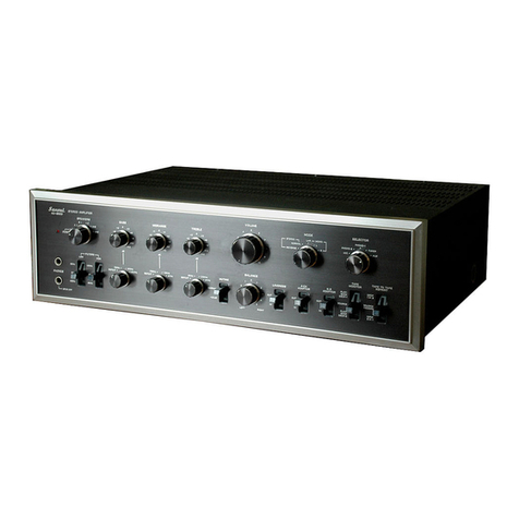
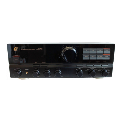
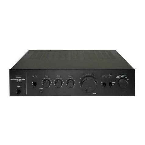
Sansui AU-7700 User manual

www.SteamPoweredRadio.Com
We
are
grateful for your choice of the
Sansui
AU-7700 stereo amplifier.
Before you degin to operate it, may we
suggest
that you
read
this booklet of ope-
rating instructions once carefully? You
will
then
be
abole to connect
and
operate
it
correctly,
and
enjoy its superb performance for
years
.
•
FUNCTIONAL
FEATURES
*Terminals
for
conneting
up
to
two
pairs
of
speakers.
In
addition
to
having the usual arrangement
of
spea-
kers in
your
listening room, another pair
of
speakers
can be
set
up
in another
room
enabling you
to
enjoy
your
music almost anywhere you like.
*Circuits
for
handling
two
tape decks
provided
.
Copying
a recorded tape
(dubbing)
can be easily
facilitated
by
simply
turning the
TAPE
PLAY
switch
.
*Terminals
for
connecting
up
to
two
turntables.
Signal cables
from
two
turntables or
two
cartridges
on one turntable can be connected.
*Selectable approved
pickup
load.
The
input
impedance
of
the PHONO-1
circuit
can be
selected
(30K.O.,
SOK.fl,
or
100K.O.)
to
best match the
approved load resistance
of
the cartridge in
use
.
*Versatile
control
or tonal
quality
possible.
The
BASS,
MIDRANGE and
TREBLE
tonal
quality
can
be adjusted
independently
of
each other. The
bass
and treble tone can be
further
finely adjusted
by
the
BASS
and
TREBLE
Tone Selectors that select the frequ-
encies
below
or
above
which
the tone controls work.
*High and
low
filter switches
provided
.
By
operation
of
these switches unpleasant noise in
the lows and highs can be e
limin
ated.
----
Table of Contents
-------------'----------
IMPORTANT PRECAUTIONS
-------
--
2
REAR-PANEL
CONNECTIONS
----------
--
3
CONNECTION
OF
SPEAKER
SYSTEMS
/Connecting Headphones - 4
BASIC
OPERATING
PROCEDURES
-----
------
--
5,
6
CONTROLLING SOUND TO YOUR
TASTE
--------------
7
PLAYING
RECORDS
AND
LISTENING TO RADIO BROADCASTS 8
TAPE
PLAYBACK
AND
RECORDING
-----------
- 9
COPYING A RECORDED
TAPE
10
CONDITIONS MIST
AKEN
FOR
BREAKDOWNS,
------
11
SIMPLE
MAINTENANCE HINTS
------------
12,
13
SPECIFICATIONS
-------------
14

www.SteamPoweredRadio.Com
I
IMPORTANT
PRECAUTIONS
To keep the set in
top
condition
all the
time,
observe
these precautions.
1.
Do
not
obstruct
the
ventilation
opening
of
the
cabinet.
2.
Avoid
an
extremely
hot
or
dusty place
or
a place
very near some heating appliance.
3.
Nine
pin
jack covers are
supplied
with
the set.
Be
sure
to
insert these cover
into
the unused
pin
jacks on
the rear panel
to
avoid dust
accumulation
.
4.
If
the set •
is
placed on a shelf, be sure
that
the shelf
board
is
thick
and strong.
HEAT RADIATED
BY
THE
SET
As
transistors are sensitive
to
heat, the enclosure
of
this set
is
designed
to
provide
a
good
dissipation
of
the
heat radiated inside this set. Thus,
if
you place some-
thing
on
top
of
the
ventilation
opening
of
the enclosure
or
place the set inside a closed box, and operate
it
for
many hours,
it
is
possible
that
the set breaks
down
.
Always
try
to
provide
a
good
circulation
of
air around
the
set.
But
removing
the enclosure
or
the
bottom
plate
to
allow
good
ventilation
is
not
only
dangerous
but
undesirable
from
the
standpoint
of
electrical per-
formance.
AC OUTLETS
Of
the three AC outlets
provided
on the rear panel,
the one marked 'SWITCHED'
is
controlled
by
the
front-
panel POWER
switch
.
It
is
convenient
to
use
it
to
power
a program source
component
such
as
your
turn-
table.
If
you keep the
power
switch
of
such a
com-
ponent
turned on, then
that
component
will
be turned
on and
off
as
you
operate the POWER
switch
of
this
set.
The
other
two
AC outlets, marked 'UNSWITCHED,'
are
not
related
to
the set's POWER switch. The voltage
delivered at these AC outlets
is
the same
as
the
power
supply
voltage used.
The 'SWITCHED'
outlet
has
a 100-watt capacity. The
two
'UNSWITCHED' outlets have a
combined
capacity
of
250
watts.
Do
not
connect
any
equipment
whose
power
consumption
exceeds the capacity
of
each
out-
lets,
as
it
is
extremely
dangerous. The
power
consump-
tion
rating
is
usually listed in the specification chart
of
the
equipment,
or
sometimes on the
equipment
itself.
---------------------------------------------------
2

www.SteamPoweredRadio.Com
TAPE PLAYER (OR DECK)
CONNECTED TO
AUX
INPUTS
(See pp.
9,
10)
PHONO
-1
PICKUP
LOAD
TAPE
DECK 1
TAPE
DECK 2
WITCH
(Seep
.
8)
1
-t
t-t--tt-+--tt-t"'"
DIN
RECORD
/
TURNTABLE
1
(
Seep
. 8)
AUX TERMINALS
(See pp.
8,
9)
PLAYBACK
CORD
=========:::.
PRE
/MAIN SEPARATE
SWITCH AND THEIR
TERMINALS
TURNTABLE
2
(
Seep
. 8)
(Seep.
12
)
■
■
~
•
I • I I •
TUNER
(
Seep
. 8)
'------
-
--
- - GROUNDING
FOR
TURNTA8LE
SPEAKER SYSTEM-B
RIGHT (See p. 4) LEFT
r===
TO
TURNTABLE,
TAPE DECK, ETC.
WALL
AC
OUTLET
SPEAKER SYSTEM-A
LEFT (S
ee
p. 4) RIGHT
=LEFT CHANNEL
-RIGHT CHANNEL
es
ee
p.
12
for
instructions about type
of
connection cords
to
u
se
.
See
other
pag
es
for
detailed instructions about various connections.
3
------------------------------------------------

www.SteamPoweredRadio.Com
SPEAKERS
~
·-------
•
~,
112,~~~
'
e
,
~~
,
~~
CONNECTION
AND
SELECTION
OF
SPEAKER
SYSTEMS
0 )
0,
o,
o,
~
(!) (!)
0,
If
you are
connecting
one pa
ir
of speaker systems
to
the set,
they
may
have any impedance
from
4
to
16
ohms. Connect them
to
the
SPEAKERS
SYSTEM-A
or
-8
terminals
on
the real panel, making sure
not
to
confuse
the
left
and
right
cables
or
the plus and minus leads on
the set and speaker ends.
The set also connects
two pa
ir
s of speaker systems.
Thus,
for
instance, one
pair
connected
to
the real-panel
SPEAKERS
SYSTEM-A terminals
may
be used in
your
own
room,
while
the
other
pair
(SYSTEM-8) in a separate
living
room
. And
if
you have connected
two
pairs
of
speaker systems and
wish
to
drive
them all simultane-
ously
by
turning
the
SPEAKERS
switch
to
A+B,
each
speaker system
should
have
an
impedance
of
more
than
8 ohms. The impedance
is
usually specified
on
the
system itself
or
in its specification. Using a system
with
a
lower
impedance
could
result in a
breakdown
of
the
set;
doing
so
will
reduce the
composite
speaker
im-
pedance in each channel
to
less
than 4 ohms.
■
CONNECTIONS
RIGHT
SPEAKER
SYSTEM
-A
LEFT
0,
OJ
OJ
0, J
ii
II
a
ir
CONNECTING
HEADPHONES
Headphone are connected
to
the
PHONES
jack on the
front
panel. Sound comes
from
the connected speaker
systems
too
unl
ess
the
SPEAKERS
switch
on the
front
panel
is
in its
OFF
position
. Therefore,
to
listen
pri-
vately
with
the headphones
only,
turn the
SPEAKERS
switch
to
OFF
.
IF
SPEAKER
SYSTEMS
ARE
OUT
OF
PHASE
If
you
were
careless
when
connecting
the speaker
systems and
if
the plus and minus polarities are
not
in
the same
order
for
the l
eft
speaker system and the
right
speaker system,
they
would
be reverse-phased. This
will
cause a '
dropout'
of
sound at the extreme ends and
the
middle
of
the
line
between the
two
speaker systems,
creating a sense
of
discontinuation
and damaging the
sense
of
stereo perspective. Also, the
bass
sound
would
lose
much
of
its powerfulness and become rather
unnatural.
Once
that
condition
is
corrected and the polarities are
in order,
you
can
detect
it
by
reproducing
a stereo
or
mono
source
with
the
MODE
switch
of
the set in the
MONO
position
. Sound
wi
ll seem
to
come
from
a
p
oint
midway
between
the speakers.
RIGHT
SPEAKER
SYSTEM
-B
LEFT
-----------------------------------
4

www.SteamPoweredRadio.Com
•
• W h
en
you operate the
va
rious switches, it
is
suggested that you reduce
the volume first by turning the VOLUME control counterclockwise.
1.
POWER
G)
POWER Switch
Raise
the lever
switch
to
ON
to turn the set on, push
it
down
to
OFF
to turn
it
off.
2.
SELECTING
SPEAKER
SYSTEMS
®
SPEAKERS
Switch
The set connects up to
two
pairs
of
speaker systems,
and this
switch
allows
selection
of
either
or
both
pairs
of
the connected speaker systems.
OFF: To
cut
off
the sound
from
the speaker systems
when
listening
with
headphones.
A: To
drive
the speaker systems connected
to
the rear-
panel
SPEAKERS
SYSTEM-A terminals.
B: To
drive
those connected to the SYSTEM-8 terminals.
A+ B: To
drive
both
A and B pairs
of
speaker systems
simultaneously.
3.
SELECTING
PROGRAM
SOURCE
@ SELECTOR Switch
Adjust
to the program source (except tape) you
wish
to
hear such
as
records and radio broadcasts
or
AUX.
PHO
NO-2,
PHO
NO-1: For playing records. The
im-
pedance
of
the
PHON0-1
circuit
can be
switched
over
with
the
PHON0-1
Pickup Load Switch on the
rear panel to match the impedance
with
the approved
. load resistance
of
the cartridge in
use
.
TU
NE
R: To hear radio broadcasts
through
a connected
tuner.
AU
X-1,
AU
X-2: To reproduce
whatever
program source
is
connected
to
the rear-panel AUX-1
or
AUX-2 inputs.
@
TAPE
PLAY Switch
Use
it
to reproduce a recorded tape
or
to
monitor
a
recording that you are making. Turn
it
to the
position
that covers the record/playback
circuit
connecting
the
tape deck in use at the
moment.
At
all
other
times,
leave it in the normal "SOURCE"
position
.
[>
When
one tape deck
is
connected
to
the set:
DECK-1, D
EC
K-2: To reproduce a recorded tape on the
tape deck connected to therear-panel
TAPE
DECK-1
or
TAPE
DECK-2 terminals.
SO UR
CE:
To hear the program source, selected
by
the
SELECTOR
switch.
[>
When
two
tape decks are connected to the set:
C
OPY
1
►
2:
To
dub
or
reprint
a recorded tape on the
tape deck (in playback
mode)
connected
to
the rear-
panel
TAPE
DECK-1
terminals
onto
a tape on
another
tape deck (in record
mode)
connected
to
the rear-
panel
TAPE
DECK-2 terminals.
D
EC
K-2: •To
monitor
a recording
as
you
dub
it
to
Deck 2 in record
mode
.
D
EC
K-1: To hear the program source
as
the signal
leaves Deck 1 in playback mode.
C
OPY
2
►
1:
To
dub
or
reprint
a recorded tape on the
deck connected
to
the rear-panel
TAPE
DECK-2 ter-
minals
onto
a tape on
another
tape deck connected
to the
TAPE
DECK-1 terminals.
D
EC
K-1: To
monitor
a recording
as
you
dub
it
to
Deck 1 in record mode.
D
EC
K-2:· To hear the program source
as
signal leaves
Deck 2 in playback mode.
eMonitoring
is
possible
only
if
the tape deck in record
mode
is
equipped
with
separate record and playback
heads.
4.
STEREO
VS.
MONO
®
MODE
Switch
When
you are
going
to
hear a stereo program source:
Leave this
switch
at NORMAL.
If
you have connected
the
left
and
right
speaker systems in reverse, set this
switch
to
REVERSE
to
restore the normal stereo effect
without
physically
changing the speaker connections.
When
you are
going
to
hear a
mono
program source:
Set
the
switch
to
MO
0,
then the
monophonic
mixture
of
the
left
and
right
channel signals
is
heard
from
both
speaker syste
ms
. The
switch
should be in this
position
to hear a
monophonic
source (record or tape) on a
turntable
or
tape deck, connected to
either
the l
eft
or
right
input
terminals on the rear panel.
e
To
hear
either
the
left
or
right
channel signal, turn
the BALANCE
control
fully
clockwise
or
counterclock-
wise.
5.
ADJUSTMENT
OF
VOLUME
@
VOLUME
Control
(J)
MUTING
Switch
The overall
volume
is
controlled
by
the VOLUME
control.
The
more
this
control
is
turned clockwise the
louder
the
volume
of
the sound becomes.
Use
the
MUTING
switch
when
you wish to reduce
the overall volume te
mporari
ly. This attenuates the
volume
by
30dB
' (
lower
position)
or
15dB
(upper
posi-
tion)
without
having to
touch
the main VOLUME con-
trol,
which
comes in very handy
when
you receive a
telephone call
or
to
eliminate
the
unp
leasant sounds
produced
when
the styl
us
is
lowered
onto
the surface
of
the record.
eAdjustment
of
the
volume
of
very
low
sounds
is
easily carried
out
by
adjusting the VOLUME
control
after the
MUTING
switch
has
been set to the '- 15dB'
position.
5
------------------------------------------------

www.SteamPoweredRadio.Com
HEADPHONE
JACK
Plug stereo headphones
into
this jack
for
private
listening
or
monitoring
. But be sure
to
turn the
SPEAK-
ERS
switch
to
OFF
first unless someone
is
listening to
the sound from speaker systems in another
room
.
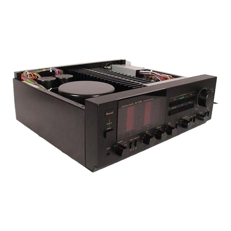
• The numbers indicated in the photograph above coincide
with
the colored switch designations.
6.
LEFT
&
RIGHT
BALANCE
ADJUSTMENTS
@
BALANCE
Control
@
MODE
Switch
The volume
of
the
left
and right speakers can be
adjusted'
by
the
BALANCE
control
(the outer ring around
the VOLUME control).
As
the
control
is
turned counter-
clockwise from the center
position
the sound
from
the
left speaker becomes
louder
than that
from
the right
speaker. When turned clockwise
from
the center, the
sound from the right speaker increases
in
volume
as
compared
with
that
of
the left.
Stereo balance adjustments are made
by
pushing
down
the MODE switch and then adjusting the BALANCE
control
so
that the sound you are listening
to
can be
heard from the exact center
position
between
both
speakers.
Reset
the switch to its original
"NORMAL"
positions
by raising it.
If
in this
case
you can
sense
some
differ-
ence in the volume between the
left
and right speakers,
recheck the program source side (stylus pressure bal-
ance, etc.).
WHEN
YOU
HEAR
ABSOLUTELY
NO
SOUND
FROM
THE
SET
:
Some
of
the symptoms and
conditions
which
seem
to
indicate a breakdown
of
the set are caused
by
wrong
operation
or
by
faulty external
com-
ponents. These
can
be spotted
with
a simple ex-
amination and restored
to
normal.
If
you suspect
a breakdown, please confirm the connections and
your
operating procedure once more.
Check List
of
Operation
1.
Is
the POWER switch turned
on?
2.
Is
the
TAPE
PLAY
switch in a position other
than "SOURCE" although you
do
not
wish to re-
produce a recorded tape?
3.
Is
the
SELECTOR
switch tu,rned
to
the correct
position?
4.
Is
the
SPEAKERS
switch turned
to
the correct
position?
5.
Is
the
PRE
/
MAIN
SEPARATE
switch on the rear
panel in the "CONNECTED" position?
Check List
of
Connections
1.
Is
the
power
cord plugged
off
a
wall
AC outlet?
2. Are the connection cords
for
your
turntable and
tape deck loose
or
touching some other object?
3. Are the speaker connection cords loose
or
de-
tached
from
the set
or
your
speakers?
4. Does each speaker system have
an
impedance
of
more than 8 ohms
when
you have connected
two
pairs
of
speaker systems and
what
to
drive
them simultaneously
by
turning the
SPEAKERS
switch to
A+
B?
Otherwise, the quick-acting fuses
protecting the
power
transistors may have
blown.
-------------------------------------------
6
.,

www.SteamPoweredRadio.Com
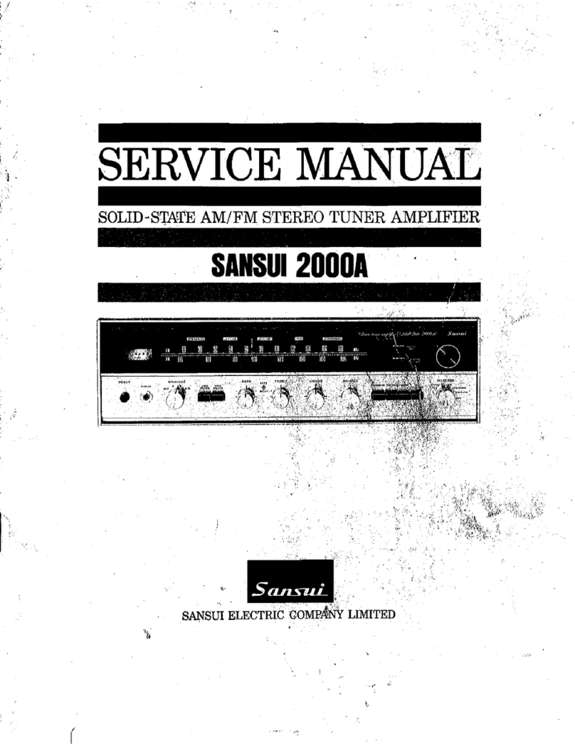
e The
numbers
indicated
in
the
photograph
above
coincide
with
the
colored
switch
designations.
TONAL QUALITY
@TONE &
FILTER
Switch
@)
BASS
Tone Selector
@
TREBLE
Tone Selector
@
BASS
Control
@)
MIDRANGE Control
@
TREBLE
Control
To
control
sound, first push
the
TONE &
FILTER
switch
down
to
the
"TONE
& FILTER"
position
.
The strength of low-frequency sound such
as
is
pro-
duced
by
a
bass
is
adjusted
with
the
BASS
control.
Turning
it
clockwise
from
the
center
emphasizes
the
lows
;
turning
it
counterclockwise
de-emphasizes
them
.
Set
the
BASS
Tone Selector
to
one
of
its
three
positions
:
600Hz, 300Hz
or
150Hz. The selector selects
the
fre-
quency
below
which
the
BASS
control
functions.
The strength of mid-frequency sound such
as
is
pro-
duced
by
a singer's
vocal
chords
is
adjusted
with
the
MIDRANGE
control.
Turning
it
clockwise
from
the
center
emphasizes
the
midrange, and
turning
it
counter
-
clockwise
de-emphasizes
them.
The
frequency
at
which
the MIDRANGE
control
functions
is
1kHz
.
Likewise, the strength of high-frequency sound such
as
generated
by
cymbals
is
adjusted
with
the
TREBLE
control.
Operation
is
the
same
as
for
the
BASS
and
MIDRANGE
controls
. The
TREBLE
Tone
Selector selects
the
frequency
(2kHz,
4kHz
or
8kHz)
over
which
the
TREBLE
control
functions
.
ewhen
you
do
not
want
to
adjust
the
tone
control
itself
to
have a flat response, set
the
TONE &
FILTER
switch
to
the
DEFEAT
position
.
Or
when
you
do
not
want
to
adjust
the
tone
control
itself
but
do
want
to
e
liminate
low-
or
high-frequency
noise, set
the
switch
to
the
FILTER
ONLY
position
. In
the
DEFEAT
position,
the
entire
tone
control
and
filter
circuits
are separated
irre
s
pective
of
positions
of
triple
tone
controls
and
filter
switches
.
@)
LOUDNESS Switch
The
human
ear
becoms
inse
nsitive
to
the
lows
and
highs
as
sound
volume
is
reduced.
So
you
may feel a
loss
of
highs and
lows
(especially
lows)
when
listening
at a
low-volume
level. The loudness
circuit
accents
the
highs and
lows
properly
to
render
the
reproduced
sound
more
realistic. Setting
the
LOUDNESS
switch
to
the
LOW
BOOST
position
accents
only
the
lows
; setting
it
to
the
HIGH &
LOW
BOOST
position
accents
both
the
highs and
lows
.
ELIMINATING NOISE
@
LOW
FILTER
Switch
@
HIGH
FILTER
Switch
To use
the
FILTER
switches, set
the
TONE &
FILTER
switch
to
FILTER
ONLY
. To use
the
FILTER
switches and
TONE
controls,
set
it
to
TONE &
FILTER.
Set
the
LOW
FILTER
switch
to
60Hz
or
20Hz
to
elimi-
nate
disturbing
low-frequency
noise such
as
hum
or
rumble
of
your
turntable
motor
. Setting
the
switch
to
60Hz
or
20Hz cuts
the
low-frequency
noise
below
that
frequency
.
Set
the
HIGH
FILTER
switch
to
?kHz
or
12kHz
to
eliminate
disturbing
high-frequency
noise such
as
the
surface scratches
of
a
worn
record,
hiss
from
a
recorded
tape
or
as
the
fluorescent
lamp
noise
mixed
in
radio
broadcasts. Setting
the
switch
to
?kHz
or
12kHz cuts
the
high-frequency
noise
above
that
frequency
.
eset
the
filter
switches
to
the
OUT
position
when
the
high-
or
low-frequency
noise
is
not
irritating
.
7
-------------------------------------------
www.SteamPoweredRadio.Com
SELECTOR
PHON0-1
-rr
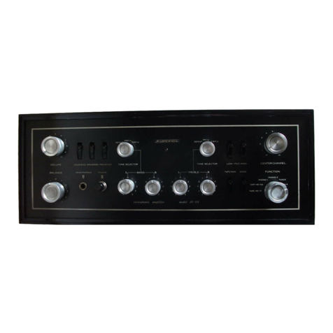
1. Turn the
SELECTOR
switch
to
PHONO-1
(or
-2)
to
play
records,
or
to
TUNER
to
hear r
adio
broadcasts.
2. Operate
your
turntable
to
play
records,
or
your
tuner
to
receive the desired station.
3.
Adjust
the various
other
controls
and switches
to
suit the
type
of
program source
you
are
going
to
hear.
■
CONNECTIONS
GROUNDING
FOR
-----
-
TURNTABLE
Connect
grounding
lead
of
turntable
to
this
GNO
termi-
nal.
But
If
hum
noise
Is
generated
then,
disconnect
it.
TURNTABLEl
TURNTABLE2
(
with
Magnetic
Cartridge
)
PHON0-1
PICKUP LOAD SWITCH
The
input
impedance
of
the PHONO-1
circuit
(or
the
load resistance
of
the connected cartridge) can be
switched
over
from
30k!l
to
SOK!l
to
100K!l
with
the
PHONO-1 PICKUP
LOAD
switch
on the rear panel. Its
purpose
is
to
match the approved load resistance
of
the
cartridge in use, since
different
cartridges have
different
load resistance values and since the magnitude
of
the
impedance
of
a
phono
input
circuit
aff_ects the_lev~I
of
high-frequency
sound among
other
things. Switch
It
over
to
find the
most
appropriate
impedance
of
the
cartridge in
use.
Most
cartridges have a load resistance value
of
SOK!}.,
which
is
why
the
input
impedance
of
the PHONO-2
circuit
is
also
SOK!}.
.
If
you
have connected
your
turn-
table
to
the PHONO-1
circuit
and find
little
difference in
the
reproduced
tone
quality
as
you
change over the
PHONO-1 PICKUP
LOAD
switch,
leave the
switch
at
the SOk!l
position
.
PHONO-1
PICKUP
LOAD
SWITCH
■■
==-.
I • I I •
TUNER
AUDIO
COMPONENT
AUX
terminals
may
be used
to
connect
component
such
as
turn-
table
with
crystal
or
ceramic
cartridge,
tuner,
tape
deck,
etc.
(See
'HOW
TO
USE
THE
AUX
TERMINALS'
on
page
9.)
-
------"'"":""""---------------------------
a

www.SteamPoweredRadio.Com
TAPE PLAY
SOURCE
1
oEcKo•
DECK
-21
COPY I
►
2
I COPY
2
►
I
LoECK
-2
DECK
.
.J
PLAYBACK PROCEDURE
1.
Set
the set's
TAPE
PLAY
switch
to
either
TAPE
DECK-1
or
TAPE
DECK-2, depending on
which
tape
play
circuit
is
connecting
the tape deck in use.
2. Operate the tape deck
to
start playback. .
3.
Adjust
the various
other
controls
and switches
to
suit the
type
of
program source you are going
to
hear.
RECORDING PROCEDURE
1. Prepare the program source
you
wish
to
record and
keep
it
ready
to
go. The
SELECTOR
switch
must be
adjusted.
2. Operate the tape deck and start
recording
.
Adjust
the record levels
with
controls
provided
on the tape
deck. The
volume
and
tone
controls
on the set
do
not
affect the sound
to
be recorded.
3. To
monitor
the sound being recorded,
follow
the
same procedure
as
for
playback after making certain
that the tape deck
it
s
elf
is
adjusted
to
permit
monitor-
ing.
If
the tape deck
only
has
a
combined
record/
play-
back head, set the
TAPE
PLAY
switch
to
the SOURCE
position
and hear the sound
before
it
is
recorded.
■
CONNECTIONS
e
Connect
TAPE DECK REC
term
i•
nals
with
recording
input
terminals
or
your
tape
deck,
and PLAY
term
I•
nals,
with
its
playback
output
terminals.
eAUX
terminals
may
be used
to
connect
tape
player
(or
deck)
for
playback
only.
Use
them
when
TAPE DECK-1 and ·2
terminals
are
already
occupied.
TAPE PLAYER (OR DECK)
CONNECTED TO
AUX
INPUTS
HOW TO
US
ETHE
AUX
TER
M
INALS
The term AUX
is
an
abbreviation
for
auxiliary.
If
your
turntable
has
a crystal
or
ceramic cartridge,
it
should be connected
to
the AUX terminals.
The AUX terminals have the same electrical
function
as
TAPE
DECK
PLAY
terminals.
So
you
can connect a
tape deck
or
player
to
them
if
your
TAPE
DEC
_K PL~Y
terminals arealready occupied. Playback
function
will
be
obtain
ed.
A tuner
or
an
amplifier-equipped
adaptor may also
be connected
to
the AUX terminals. The AUX terminals
have
an
input
sensitivity
of
100
millivolts
.
So
most
audio
components
having
an
output
voltage
of
100
millivolts
or
more
can be connected.
If
you are
not
certain
whether
you can
connect
a particular
com-
ponent
to
the AUX terminals,
look
up its operating
manual
or
specifications.
• DO
NOT
connect
tape
deck
to
TAPE
DECK·l
REC
and
PLAY
pin
jacks
and
REC
/PLAY
DIN
socket
slm
ultaneously.
9
-------------------------------

www.SteamPoweredRadio.Com
TAPE
PLAY
SOURCE
r
oECK
OI
DECK
-
Z7
COPYl ►
Z
I
COPYZ
►
I
lo
E
CK
-Z
DECK
-
1J
1.
To undertake tape
-to-tape
dubbing
:
Set the
TAPE
PLAY
switch
to
the COPY
1
►
2
/
DECK-1
position
when
you
are
dubbing
a tape deck
(in
play-
back mode), connected
to
the rear-panel
TAPE
DECK-1
terminals,
onto
another tape deck
(in
record mode),
connected
to
the rear-panel
TAPE
DECK-2 terminals.
When
you
dubbing
a tape deck (in playback mode),
connected
to
the rear-panel
TAPE
DECK-2 terminals,
onto
an
other
tape deck (in record
mode)
, connected
to
the rear-panel
TAPE
DECK-1
terminals, set the
switch
to
the COPY
2
►
1
/
DECK-2
position
.
2.
Operate the tape decks and start recording.
Adjust
the record levels
with
controls
provided
on the tape
deck in record
mode
.
Controls
and switches
on
the set
do
not
affect the recording.
3.
To hear
or
monitor
the signals just recorded,
turn
the
TAPE
PLAY
switch
to
the
position
of
the tape deck in
record mode, COPY
1
►
2
/
DECK-2
(when
you
are
dubb-
ing
(rom
Deck 1
to
2)
or
COPY
2
►
1
/
DECK-1
(from
Deck
2
to
1).
eMonitoring
is
possible
only
if
the tape deck in record
mode
is
equipped
with
separate record and playback
heads;
do
not
turn
the
TAPE
PLAY
switch
to
COPY 1
►
2/
DECK-2
or
COPY
2
►
1
/
DECK-1
if
that
tape deck
is
equip-
ped
with
a record/playback
combination
head. This
is
further
explained in the table
below
.
CONNECTING
TWO
OR
MORE
TAPE
DECKS
This set
is
provided
with
two
tape re
cord
/playback
circuits
. Both,
TAPE
DECK-1
and
TAPE
DECK-2 terminals,
have identical
functions
and specifications.
When
con-
neting
two
tape decks, in
addition
to
recording
or
re-
producing
either
tape deck,
you
can
dub
a tape on one
tape deck
onto
another
by
simply
setting the
TAPE
PLAY
switch
to
the
appropriate
position
.
A
third
tape deck may be connected
to
the AUX-1
or
AUX-2 terminals on the rear panel
for
playback. Then
a tape
on
that
tape deck can be
dubbed
onto
the tape
decks, connected
to
the
TAPE
DECK-1
or
-2 terminals
on the rear panel. Turn the set's
SELECTOR
switch
to
AUX-1
or
AUX-2 and
follow
the
proc
edures in the sec-
tion
"TAPE PLAYBACK
AND
RECORDING" on the pre-
ceding
page.
•
Do
not
connect
tape decks
to
the
TAPE
DECK-1
terminals and
DIN
socket on the rear panel simultane-
ously.
■
OPERATING
TAPE
PLAY
SWITCH FOR
COPYING
A RECORDED
TAPE
Mode
of
Each
Connected
Tape Deck Position of
TAPE
PLAY
Switch You Hear:
TAPE
DECK-1
TAPE
DECK-2
inputs inputs
PLAYBACK RECORD COPY
1
►
2
/
DECK-1
Sound being recorded.
COPY
1
►
2
/
DECK-2
Sound just recorded
.*
COPY
2
►
1
/
DECK-1
Sound just recorded
.*
RECORD PLAYBACK COPY
2
►
1 /
DECK-2
Sound being recorded.
AUX-1 or DECK-1 or
AUX-2 DECK-2 Position of
TAPE
PLAY
Switch You Hear:
inputs inputs
SOURCE
Sound being recorded.
PLAYBACK RECORD DECK-1
or
DECK-2 Sound
just
recorded.*
*
Monitoring
is
possible
only
if
the tape deck in record
mode
is
equipped
with
separate record and
playback heads.
----------------------------------------------
10

www.SteamPoweredRadio.Com
PROGRAM
SYMPTOM
PROBABLE
CAUSE
WHAT
TO
DO
SOURCE
TUNER * Noise
during
AM
recep- * Interference
by
adjacent sta- * Peculiar
to
AM
waves, and
unavoid-
tion
. tions. (Called beat
interfer-
able
to
some extent.
ence.)
* TV set
is
being used simulta-
neously.
*
Move
TV set away
from
tuner and set.
* Noise heard at certain * Interference
by
nearby elec- *
Attach
noise
limiter
to
appliance
hours, in certain areas
or
trical appliances.
producing
noise.
over part
of
dial
during
* In some cases, can be
eliminated
by
AM
reception. reversing
power
cord
plug-AC
outlet
connections.
* Pop noise
during
FM
re- *
Ignition
noise
from
nearby *
Adjust
antenna
location
and height
ception
.
automobile,
motorcycle,
etc.
for
maximum
sensitivity.
* Keep antenna away
from
streets.
Note:
In
many
cases,
high-frequency
noise
during radio reception cannot
be
entirely eliminated. Try turning
on
set's
HIGH
FILTER
switch or
turning
TREBLE
control counterclockwise.
TURNTABLE *
Hum
noise. * Unshielded cables used
to
* Use regular shielded cables.
connect
turntable
.
*
Minus
(ground)
wire
of
con-
* Examine
connecting
cables, especial-
necting cable
is
not
connect-
ly
their
plugs.
ed
completely.
* Turntable
motor
or
tonearm *
Connect
grounding
lead
of
turntable
is
not
grounded.
to
set's
GND
terminal.
* Loud osciIla
ting
noise. * Turntable
is
placed on
top
* Place
thick
cushion between
turnta-
or
too
close
to
speaker sys-
ble
and speaker system.
terns. * Change
location
of
turntable
and
speaker systems.
* Sound
is
shaky. * Dust on record
or
pickup
* Clean record and
pickup
stylus.
stylus.
*
Worn
pickup
stylus. * Replace
pickup
stylus.
*
Improper
stylus pressure. *
Adjust
stylus pressure.
TAPE
DECK
* Hiss noise. *
Magnetic
heads are magne- * Demagnetize heads.
tized. * Turn on HIGH
FILTER
switch
.
*
Connect
noise
reduction
adaptor.
* Sound
is
not
clear. * Dust on magnetic heads. * Clean heads.
* Tape
is
not
pressed
tight
to
*
Align
tape transport mechanism.
heads.
GENERAL
*
When
left
and
right
* Left and
right
channel signal * Never
mind.
Optimum
stereo effect
channel sound volumes strengths vary
with
program
is
obtained
by
adjusting BALANCE
are balanced
with
set's source.
control
so
that
sound comes
from
BALANCE
control,
it
* Left and
right
speaker sys-
midway
point
between
two
speaker
does
not
come
to
center terns have
different
efficien-
systems.
position
. cy.
* Musical instruments and * Left-right, plus-minus
con-
* Examine connections once
more
.
singer
not
located nections
of
speaker systems
clearly.
input
cables are wrong.
11
---------------------------------------------------
www.SteamPoweredRadio.Com
CONNECTION
CORDS
Be
sure
to
connect
your
turntable, tape deck and
speakers
firmly.
Be
careful
that
the
connection
plugs
are
not
loose
from
the jacks
or
the leads
of
the
con-
nection
cords are
not
touching
other
parts.
If
the
con-
nections are
imperfect,
noise may be generated and,
eventually, the set may break
down
.
It
is
advisable
to
follow
the instructions given
by
the manufacturer
of
the
equipment
you are connecting.
CONNECTION CORDS
WITH
RCA
TYPE
PLUGS:
These
are shielded cords
with
an
RCA ·
type
plug
so
ldered
to
each end. They are used
to
connect
a turntable, tape
deck and
other
program source components.
Try
to
keep the cords
as
short
as
possible.
If
you
use
lon
g
cords, the
high-frequency
signals
tend
to
be attenuated.
Their
maximum
length should be
two
meters (7 feet).
If
such cords are already
supplied
with
your
tape deck
or
turntable,
it
is
advisable
to
use
them
.
DIN
RECORD/
PLAYBACK
CORD: This
is
a
combined
2-channel stereo record/playback cord, standardized in
Germany. This set
has
a special
5-pin
socket marked
TAPE
REC
/
PLAY
on the rear panel
to
accept such a cord.
It
can be used
only
if
your
tape deck
has
an
identical
socket.
PVC
CORDS: These are used
to
connect
your
speak-
ers, and are basically the same
type
of
vinyl-covered
cords
as
the
power
cords
from
your
TV set
or
radio
.
Peel
the
vinyl
covering
off
each end
of
the cord, care-
fully
interwine
the lead wires, then
connect
it
to
your
speaker and the set. To prevent
mis-connection
,
it
is
advisable
to
paint-color
to
each cord.
Color-coded
cords are available at some appliance stores.
SHORT-CIRCUIT PIN
PLUGS
When
you unpack the set,
you'l
l find special
pin
plugs inserted
into
the PHONO-2 jacks. Their
function
is
to
short-circuit
the plus and minus terminals
of
the
input
cir
cu
it
and thus
pr
event a
ny
noise
from
being
generated
by
them
when
these jacks are
not
in
use.
Therefore,
if
you
use
the PHONO-2 jacks, r
e-position
these plugs
into
the PHONO-1 jacks.
Or
,
when
both
PHONO-1 and PHONO-2 jacks are used, keep them
elsewhere
for
later use.
Do
NOT
insert them
into
the
output
jacks (such
as
TAPE
REC),
or
the sound
from
the
set
will
be
cut
off
.
PRE
/
MAIN
SEPARATE
SWITCH
On
thi
s set the
output
terminals
of
the
pr
eamplifier
and the
input
terminals
of
the
power
amplifier
are con-
nected
by
the
PRE
/
MAIN
separate switch. To slide
it
to
the "SEPARATED"
position
separates the
preamplifier
from
the
power
amplifier,
allowing
you
to
use
them
independently
.
If
you
are
not
going
to
connect
an
ex-
ternal
preamplifier
or
power
amplifier
(or
some other
additional
unit)
to
these terminals, be sure
to
keep the
switch
to
the "CONNECTED"
position
. Also, whenever
you
try
to
slide the
switch,
be sure
to
turn the set's
POWER
switch
off
befor
ehand.
The separation
of
the
preamplifier
and the
power
amplifier
offers a
number
of
useful applications.
One
of
them
is
a so-called
electronic
crossover system. In
this system, each speaker
unit
(woofer,
midrange,
tweeter, etc.) in each speaker system
will
be driven
by
a
separate
power
amplifier
. But,
to
do
this, you
will
first
need
an
electronic
crossover
divider
. And,
of
course,
you
will
need one
or
two
stereo
power
amplifiers in
addition
to
the set's
own
power
amplifier,
depending
on
whether
you
wish
to
build
a 2-way
or
3-way electro-
nic
cross-over system. The speaker systems,
of
course,
must also be
2-way
or
3-way.
Once
all these
compo-
nents are ready, slide the
PRE
/
MAIN
separate
switch
to
the
"SEP
ARATED"
position,
and
connect
the
input
terminals
of
the
electronic
crossover
unit
with
the
PRE
OUT
terrr.inals
of
the set, and the
output
terminals
of
the crossover
unit
with
the
MAIN
IN terminals
of
the set.
Connect the
additional
amplifier(s)
so
the
electronic
crossover
unit,
and finally,
connect
the
output
terminals
of
the amplifier(s)
to
each speaker unit.
PRE
/MAIN SEPARATE
SWITCH
MAIN (POWER) AMP. INPUTS
OF
THIS SET
PRE
AMP. OUTPUTS
OF
THIS SET
------------------------------------------------
12

www.SteamPoweredRadio.Com
BEFORE
SENDING THE
SET
OUT
FOR
SERVICING
Some
of
the symptoms and
conditions
which
seem
to
indicate a
breakdown
of
the set are caused
by
wrong
operation
or
by external
components
. These can be
spotted
with
a simple examination and restored
to
normal.
If
you suspect a
breakdown,
please
confirm
the
connections and
your
operating
procedure
once
more
.
Here are
some
useful hints:
First,
if
you hear absolutely no sound
from
the set,
inspect
your
turntable, tape deck and
other
program
source components, then examine this set and
your
speakers in that order, paying
attention
to
both
their
connections and operation.
Be
sure
to
reduce the
volume
beforehand.
Second,
if
the sound fails
to
come
out
only
when
you
play records, reproduce a recorded tape
or
receive
broadcasts, then chances are
that
only
the
particular
program source
component
may be
wrongly
connected.
If
loud
hum
noise
of
constant loudness
is
heard,
it
may
be
suppressed
by
connecting
the
grounding
lead
or
terminal
of
your
turntable
or
tape deck
to
the set's
GND
terminal, using PVC
cord
.
Or,
more
simply,
re-
versing the
connection
between the set's
power
cord
plus and the
wall
AC
outlet
may stop it.
CHECK
LIST
OF
OPERATION
1. ·
Is
the
power
switch
turned on?
2.
Is
TAPE
PLAY
switch
set
to
SOURCE
when
you
do
no
wish
to
reproduce
a recorded tape?
3.
Is
the
SELECTOR
switch
turned
to
the
correct
posi-
tion?
4.
Is
the
volume
control
turned
to
an
appropriate
level?
CHECK
LIST
OF
CONNECTIONS
1.
Is
the
power
cord
inserted
into
a
wall
AC outlet?
2. Are the
connection
cords
for
your
turntable
and tape
deck loose
or
touching
some
other
object? Are you
using shielded cords?
3. Are the speaker
connection
cords loose
from
set
or
your
speakers?
After
you have made the above examination and made
the required corrections,
if
the set fails
to
operate
normally, there may be something
wrong
with
the
set itself. In such a
case,
please contact the dealer
from
whom
you purchased
it
or
your
nearest SANSUI
AUTHORIZED
SERVICE
STATION.
ABOUT
THE VOLTAGE ADJUSTMENT
Your
set
is
adjusted
to
operate at the correct
power
supply
vo
ltage
of
your
area
prior
to
shipment
from
our
factory.
If
you
move
after purchasing
it
or
send
it
as
a
gift
to
a
friend
living
in
an
area
where
the voltage
is
different,
it
may
be necessary
to
adjust its Voltage Selector.
To adjust
it,
remove
the
two
screws securing the
name
plate
on
the
rear panel, then set the
arrow
mark
on the Voltage Selector Plug
to
the
correct voltage
indication
(100, 117,
220
or
240
volts).
It
may be
necessary
to
replace the
power
fuse
as
well
whene-
ver the voltage
has
changed. For
operation
at
100
to
117
volts, use a 6-ampere fuse. For
operation
at
220
to
240
volts,
use
a 3-ampere one.
SHOULD
THE POWER
FUSE
BLOW
If
no Power
Indicator
should
glow
and the set
simply
remains dead even after
you
have turned on its POWER
switch,
it
is
possible
that
its
power
fuse
has
blown
.
If
this happens, disconnect
the
power
cord
from
the
wall
AC
outlet
at once and examine the
power
fuse on
the rear panel.
If
you
find
it
blown,
replace
it
with
a
new
glass-tubed fuse
of
the rated capacity (6-ampere
for
100
to
117
volts, 3-ampere
for
220
to
240
volts).
Never
use
a fuse
of
a
different
capacity
or
a piece
of
wire,
even
as
a stop-gap measure,
or
serious danger
could
result.
13
---
-
-----
-
----------------------------------
www.SteamPoweredRadio.Com
POWER OUTPUT (at rated
distortion)
CONTINUOUS
RMS
POWER
OUTPUT
...
. .
...
54
Watts
per channel x 2
(both
channels
driven)
LOAD
IMPEDANCE
........
8.0.
POWER BAND
...........
.
20
to
20
,000Hz
TOTAL
HARMONIC
DISTORTION
...
.
....
le
ss
than 0.1%
(from
AUX)
Music
power
(IHF
).
....
.
.......
. . .
250W
(4 n
l,000Hz
)
140W (Bn
l,000Hz
)
Continuous
rms
power
output
..
55
+5
5W (Sn
l ,
000Hz
)
INTERMODULATION
DISTORTION
(a
t rated
power
output
70Hz: 7,000Hz= 4: 1
SMPTE
me
thod
)
OVERALL .
..
..
.
..
......
le
ss
than 0.
15
%
PREAMPLIFIER
ONLY
. . . .l
es
s than
0.1
%
POWER (
MAIN)
AMPLFIER ONLY
......
. .
less
than 0.1%
FREQUENCY
RESPO
SE
(at 1
Watt
output
)
OVERALL . .
..
.
.......
..
10
to
50,000Hz
:::?
5
dB
POWER (
MAIN
) AMPLIFIER ONLY
.
.......
5
to
50
,000Hz
:::?
dB
EQUALIZATION (RIAA curve)
...
..
. . .
30
to
15,000Hz ± 0.5dB
DAMP! G FACTOR
....
..
30
(
8.0.
)
I
PUT
SENSITIVITY
AND
IMPEDANCE
(1KHz,
for
rated
power
output
)
PHONO-1
..
...
.
..
...
...
2.
5mV
30K!1,
50KD
, 100KD.
adjustable
PHONO
-2
..
.
.....
..
....
2.
5mV
50KD
(
Max
.
input
capability
: 300mV at 0.2%
total
harmonic
distortion
)
TUNER
..........
.
..
.
.....
.
..
. .100mV 50KD.
AUX-1 &
-2
..
. . .
....
..
......
. . .100mV 50KD.
TAPE
DECK-1 & -2 (Pin Jacks)
....
100mV 50KD.
TAPE
DECK-1 (
DIN
Socket)
....
. .100mV 50KD.
MAIN
IN .
...
.
................
.800mV 50K!1
OUTPUT
LEVEL
(1KHz)
TAPE
DECK-1 & -2 (Pin Jacks)
....
100mV
TAPE
DECK-1
(DIN
Socket)
... ...
30mV
PRE
OUT
...
...
.
...............
800mV
(Max.
output
level: 5V at 0.5%
total
harmonic
distortion)
CHANNEL SEPARATION
(1KHz,
for
rated
power
output)
PHONO-1
& -2
..
. .
...
.
......
..
better
than 50dB
TUNER
...
.
..
. .
...
.
............
better
than 55dB
AUX-1 & -2 . .
.....
.
............
better
than 55dB
TAPE
DECK-1
&
-2
....
.
.........
better
than 55dB
MAIN
IN
....
..
. .
..
.
...........
be
tter
than 60dB
HUM
AND
NOISE (IHF)
PHONO-1 & -2 . .
....
...
...
. .
..
better
than 75dB
TUNER .
........
..
.
...
.....
.
..
.
better
than 85dB
AUX-1
&
-2 . .
..................
be
tter
than 85dB
TAPE
DECK-1 & -2
..
.
..
.
.. ..
....
be
tter
than 85dB
MAIN
IN
....
.....
....
.....
.
..
.be
tter
than 100dB
SWITCHES
AND
CONTROLS
BASS
(± 5 steps)
..
. .
...
. ± 13dB at 50Hz
TONE
SELECTOR
(TURNOVER FREQUENCIES)
....
.
...
150Hz, 300Hz, 600Hz
MIDRANGE(
± 5 steps)
..
±5dB at 1KHz
TREBLE
(± 5 steps).
.....
±13dB at 15KHz
TONE
SELECTOR
(TURNOVER FREQUENCIES)
.....
...
2KHz, 4KHz, 8KHz
LOUDNESS
(Volume
Control
: - 30dB)
LOW
BOOST
..
...
...
. . + 10dB at 50Hz
HIGH &
LOW
BOOST
..
+10dB at 50Hz
+ 8dB at 10kHz
LOW
FILTER
.
....
. . .
..
. . - 3dB at 20Hz (12dB/oct.)
-3dB at 60Hz (12dB/oct.)
HIGH
FILTER
. .
....
.
...
. . - 3dB at 7KHz (6dB/oct.)
-3dB at 12KHz (12dB/oct.)
MUTING
. .
..........
. . . . - 30dB, -15dB
POWER REQUIREMENTS
..
100, 117,220, 240V
50
/60Hz
POWER
CONSUMPTION
..
120W (rated), 350W (max.)
DIMENSIONS
........
. . . .434mm (17½
")
W
130mm ( 5
½"
)
H
315mm (12
¼"
) D
WEIGHT
......
.
.........
12
.3Kg (27.1 lbs)
• Desi
gn
and
s
pecin
c
at
i
on
s
ub
ject
to
change
wi
thout
not
ic
e
for
improvements
.
LIST
OF
ACCESSORIES
1.
PIN JACK COVER
...
.
......
.
..
...
......
..
. . 9
2. OPERATING INSTRUCTIONS .
.. ..
. .
...
. . . . 1
3. OPERATING INSTRUCTIONS
SHEET
....
.
...
1
Operating
Instructions
StocK
No.
9208
25
0
--------------------------------------------
14

www.SteamPoweredRadio.Com
SAN
SUI
AU-7700
SCHEMATIC
DIAGRAM
_______________
•D_esig_nan_dsp_ecifl_catio_nss_ubjec_tto_cha_nse_with_out_notic_efo_rim_prov_eme_nts.
.
F:2Q@
LEFT
CHANNEL
Pt/ONO
l I
PHONO
2
'
~~-~
·~
TUNER
AUX J
AUX 2
rREC
DECK-I
4'LAr
rREC
DECK-2
LptAY
PRL
OUT
RIGHT
~-
=
~--
CHANNEL
PHONG
1
PHONG
2
AUX
!
AUX
2
rREC
DECK-7
LPLAY
I<>+-~.++++--<
I
L _
SELECTOR
F-2092
S01a.~d
1.
PHONG
2
2.
PHONG
l
3.
1UNER
4.
AUX
1
5.
AUX
2
TAPE
PLAY
F-2092
Sttzo.-f
1.
COPY
1-
2
DECK
-2
"SPEAKERS
2.
DECK-I
3.
DECK-/
4.
SOURCE
5.
DECK-
2
6.
COPY
2 - 1
D£CK-2
7. DECK-/
Sroza~d
1.
OFF
2. A
3.
B
4. A+B
1F-2.9j_f]
,
~fVIJJ/1'"<
mvn:
Sd,a
Soza
19
24V
24 I
VOLUME
F-1093
VRo,.dz
BALANCE
F-2093
VRoJ,Q4
TREBLE
F-2095 VR01,02
MIOFlAN5
F-2095
VR03,04
BASS
F-2095
V/1,,,06
23 I
-25V
25
MODE
F-2094
So,a~,
1.
REVERSE
2.
NORMAL
3.
MONO
MUTING
F-2094
Soza,b
1.
-l5d8
SYMBOL
.:i.
CER.AMIC
e>
MYLAR
□
STYROL
®
TANTALUM
2.
OUT
3.
-30dB
ALL
RESISTORS
14
WATTS
UNLESS
OTHERWISE
NOTED
.
LOUDNESS
F-2094
SoJa.,b
1.
LOW
BOOST
1.
OUT
3.
HIGH
HOW
BOOST
FILTERS
F-2096 Sosa-d
1.
?KHz
HIGH
2.
OUT
3.
72KHz
FILTERS F-2096
So4a-d.
1.
60Hz
LOW
2.
OUT
3.
2GHz
25
-25
V
I
L__
-1
r.O•U
VRo,
-VRo6
50K(8)
I I
11·.I . 2 3
4-
5 6 7 8 9
JO
!1
J
~
-
-
~~~
-
TONE
k FILTER
F-2096
5o,a.-.d
1.
FILTER ONLY
2.
DEFEAT
3.
TONE
k FILTER
TONE
SELECTOR
I-
-
2096
S02a.-d
1.
21<.Hz
TREBLE
2.
4KHz
3.
BKHz
TONE
SELECTOR
F-2096
S03a.~d
I.
600Hz
BASS
1.
30GHz
3.
150Hz.
R13
R,s
R,1
4.?K
12K
IK
TRa,
TR01
2SCl313R
(F,G)
POWER
Sw, l.
OFF
2.
ON
PICK
UP
LOAD
F-2413
SoJa,b
1.
30KQ.
1.
50KQ
3.
l(X)KQ ~ -
PP£-MA/N F-2473 S04
a,b
1.
SEPARATED
2.
CONNECTED
AC
0!60Hr
F701
JOO~l!?V6A
2?0--24{)V
3A
L
___
J
LA
Mod£L
Only
T701
LUE
~~~
~~;
I,
I
CSA Mod.el On{y
F077A
I
j
0
"'
m
0
(/)
12
10
~
·-
ol
~
t
'-'
TRo,,03
TR,-,
2SC71 I
(E,F,G)
2SA726(F,G)
TR09
(L,K)
TRn
TR2-;n I
2SC959
2S0382
2sci619A(R,O,Y)I
TR11
(M,L)
2SC735(0,Y)
TR1.3
TR,.9
(M,L)
TR,s
2SCI
124
( 1,2)
2SA606(L,K)2S8537
TR
TR,,
2SA8O8A
2SA562(0,Y)
TR,z,u
(R,0Y)
TRos
rR10,12
TR,o
Printed
in Japan (
84M200
)

www.SteamPoweredRadio.Com
CAUTION
CARD
1.
Ne\·er
expose
this
amplifier
to
direct
sunlight.
Keep
away
from all
thermal
sources
and
heat
generators.
0
Before
turning
the
amplifier
on,
be
sure
the
lead
wires
from
the
speakers
are
properly
connected
at
both
output
and
input
terminals.
3.
Before
turning
the
amplifier
on.
be
sure
that
all
connections
-
antennas,
pin-jacks, wires, etc. -
are
properly
made
fur
whatever
component
or
program
source
to be
employed.
,I
.
Always
minimize
the
amplifier's
Volume
Control
when
using
the
function
Selector
Switch
or
when
turning
on
components.
\\'hen
changing
connec1ions
between
the
amplifier
and
components,
it
is
strongly
recomrnendcd
that
the
amplifier's
AC
power
cord
he
rt
..'
!110\
·cd from
i1s
AC
outlet.
5.
If
there
is
no
sound
from
the
speakers,
or
the
sound
is
distorted,
turn
down
the
Volume
Control
and
discorrnt·ct
the
amplifit•r's
/\C
power
supply
cord.
Then
tract
•
the
-;ource
of
thc
trouble
with
the
aid
of
the
Operating
Instruction
supplil·d.
ti.
;\;t•\·er
connect
two
or
more
speaker~;
to
one
tcrminal.
Doing
so will
cause
serious
damage.
note:
For
correct
operation.
follow
our
Operating
Instructions
manual.

www.SteamPoweredRadio.Com
SANSUI INTERNATIONAL WARRANTY
SAN
SU
I ELECTRIC COMPANY, LTD.,
warrants
all Sansui
products
purchased
in one
country
and
taken
abroad
against
defects
in
materials
and
workmanship
for
the
period
(s)
enumerated
under
"Terms
of
Warranty
"
from
the
original
purchase
date.
Provided
that
the
holder
bears
all
costs
for
insuring
the
safe
delivery
and
return
of
his
equipment
to
and
from
the
nearest
authorized
Sansui service
station,
repairs
and
parts
replacement
will
~
made
without
charge
anywhere
in
the
world,
subject
to
the
following
exceptions
:
1.
Failure
to
present
both
sales slip (or
its
equivalent
)
and
this
Warranty
card
.
2.
Breakdowns
or
damage
due
to
careless
handling,
negligence,
accidents,
abuse
or
failure
to
follow
operating
instructions
furnished
by
Sansui.
3.
Breakdowns
caused
by
other
appliances
.
4.
Breakdowns
or
damage
due
to
natural
disasters,
acts
of
war
or
public
disturbances
.
5. Repairs,
alignments,
alterations
or
tampering
with
the
product
by
individuals
or
service
stations
other
than
those
specifically
designated
by Sansui in
the
accompanying
list
of
International
Authorized
Service
Stations
.
6.
Breakdowns
or
damage
due
to
packaging
and
shipment
in
containers
other
than
those
provided
or
designated
by
Sansui.
7.
Equipment
with
serial
numbers
altered
or
removed
.
Products to which the above exceptions
apply
will be serviced
at
cost
to the owner.
TERMS
OF
WARRANTY
PRODUCTS FREE L
AB
OR
FREE PARTS EXCE
PTION
S
Receivers,
Tuners
&
Amplifiers
12
Months
24
Months
A
4-
Channel
Synthesizer
Decoders
12
Months
24
Months
A
Electronic
Crossover
Units
12
Months
24
Months
A
Reverberation
Amplifiers
12
Months
24
Months
A
Turntables
12
Months
12
Months
B
Speaker
Systems
12
Months
12
Months
·
C
Stereo
Headphones
12
Months
12
Months
-
Stereo
Systems
12
Months
12
Months
D
Tape
Decks
&
Recorders
6
Months
12
Months
E
A .
With
the
exception
of
pane
ls.
knob
s,
bonnet.
s
moked
plate
and
dial
glas
s.
B .
With
the
exception
of
sty
l
us
,
knob
s.
head
s
hell
,
acrylic
du
st
cover
and
all
w
ooden
part
s.
C .
With
the
exception
of
all
wooden
part
s.
D .
With
the
except
i
on
of
all
wooden
part
s,
panel
s.
kno
bs. s
moked
plate
s,
dial
gla
ss,
head
shell
and
s
tylu
s.
E . W
it
h
the
excepti
on of
all
w
ooden
pa
rts
,
panel
s,
kn
o
bs,
smoked
plates,
meter
covers,
dust
co
v
ers,
ta
pe
head
s,
an
d all oth
er
pa
rts
liste
d as a
ccess
o
ries
.
This
International
Warranty
is in lieu
of
all
ot~er
Warranties
expressed,
implied
or
statutory
and
is
made
on
the
express
understanding
that
it
may
be
invoked
only
by
the
original
pur-
chaser
and
covers
only
those
Sansui
products
purchased
in
one
country
and
presented
for
servicing
and
/
or
repairs
in
another
.
Proof
of date
of
purchase
is
considered
to
be a responsibil
it
y of the
customer
and
must
be
presented
when
applying
for
In-Warranty
Service
at
an
authorized
S
AN
SU
I Service
St
a
ti
on.
Other manuals for AU-7700
3
Table of contents
Other Sansui Amplifier manuals

Sansui
Sansui 3000 User manual

Sansui
Sansui AU-D33 User manual

Sansui
Sansui B-1000 User manual

Sansui
Sansui AU-7700 User manual

Sansui
Sansui AU-G99X User manual

Sansui
Sansui AU-70 Troubleshooting guide

Sansui
Sansui C-2101 User manual

Sansui
Sansui AU-4900 User manual

Sansui
Sansui AU-X911DG User manual

Sansui
Sansui 310 Troubleshooting guide

Sansui
Sansui AU-777 User manual

Sansui
Sansui AU-X701 User manual

Sansui
Sansui RA-990 User manual

Sansui
Sansui AU-7700 User manual

Sansui
Sansui 350A User manual

Sansui
Sansui AU-2200 User manual

Sansui
Sansui AU-555 Troubleshooting guide

Sansui
Sansui AU-9900A User manual

Sansui
Sansui AU-517 User manual

Sansui
Sansui 1000A Troubleshooting guide