Sansui AV-99 User manual

a
Le
TS
OE
OPERATING
INSTRUCTIONS
MODE
D’EMPLOI
ea
aa

CAUTION
RISK
OF
ELECTRIC
SHOCK
.
00
NOT
OPEN
CAUTION:
TO
REDUCE
THE
RISK
OF
ELECTRIC
SHOCK,
DO
NOT
REMOVE
COVER
(OR
BACK).
NO
USER-SERVICEABLE
PARTS
INSIDE.
REFER
SERVICING
TO
QUALIFIED
SERVICE
PERSONNEL.
The
lightning
flash
with
arrowhead
symbol,
within
an
equilateral
triangle,
is
intended
to
alert
the
user
to
the
presence
of
uninsulated
‘‘dangerous
voltage”’
within
the
product's
enclosure
that
may
be
of
suffi-
cient
magnitude
to
constitute
a
risk
of
electric
shock
to
persons,
The
exclamation
point
within
an
equilateral
triangle
is
intended
to
alert
the
user
to
the
presence
of
im-
portant
operating
and
maintenance
(servicing)
in-
structions
in
the
literature
accompanying
the
appliance.
ABO
ADR
L000
TY
ANA
AN
0
BA
AO
8°
AI
A
Yt
WARNING:
To
prevent
fire
or
shock
hazard,
do
not
expose
this
appliance
to
rain
or
moisture.
e
The
Model
No.
and
Serial
No.
of
your
unit
are
shown
on
its
back
panel.
0
AH
TO
8°
A
8
IND
IR
A
FT
I
AN
NN
CAUTION
RISK
OF
ELECTRIC
SHOCK
00
NOT
OPEN
ATTENTION:
POUR
REDUIRE
LES
DANGERS
DE
DECHARGE
ELECTRIQUE,
NE
PAS
ENLEVER
LE
COUVERCLE
(OU
LE
PANNEAU
ARRIERE).
L’APPAREIL
NE
RENFERME
AUCUNE
PIECE,
REPARABLE
PAR
L‘UTILISATEUR.
CONFIER
TOUTE
REPARATION
OU
ENTRETIEN
A
UN
PERSONNEL
QUALIFIE.
Le
symbole
a
fléche
brisée
dans
un
triangle
équilaté-
ral
a
pour
but
d’attirer
l’attention
de
I’utilisateur
sur
la
présence,
a
l‘intérieur
du
coffret,
d'une
“tension
dangereuse’’
non
isolée
qui
est
d'une
importance
suf-
fisante
pour
constituer
un
risque
de
décharge
élec-
trique
pour
les
6tres
humains.
Le
point
d’exclamation
dans
un
triangle
équilatéral
a
pour
but
de
signaler
a
l'utilisateur
la
présence
d'explications
importantes,
relatives
a
l’exploitation
et
a
I’entretien,
dans
ie
texte
accompagnant
l'appareil.
AE
A
TN
A
ER
AA
AI
MN
AO
MY
A
8
AN
ATTENTION:
Pour
éviter
les
dangers
d’électrocu-
tion
ou
d’incendie,
ne
pas
exposer
cet
appareil
a
la
pluie
ou
a
I’humidité.
e
Lenuméro
du
modéle
et
le
numéro
de
série
de
I’appareil
sont
ins-
crits
sur
son
panneau
arriére.
BESS
A
IS
NA
ET"
ESM
NSO
SNS
MN
AI
RM
Thank
you
for
purchasing
this fine
SANSUI
product.
Taking
the
time
to
read
these
operating
instructions
carefully
before
use
will
acquaint
you
fully
with
all
its
features
and
help
ensure
optimum
performance.
*
In
order
to
simplify
the
explanation
illustrations
may
sometimes
differ
from
the
originals.
*
This
unit
is
not
designed
for
professional
use.
Consequently,
the
colors
of
the
color
bars
and
background
color
may
vary
depending
upon
the
way
in
which
the
unit
is
used.
PrOCaUtiONS
2.
cscidsivernccisedenecescsedawees
Features
..........ccc000
souuadbandetadeaaacasees
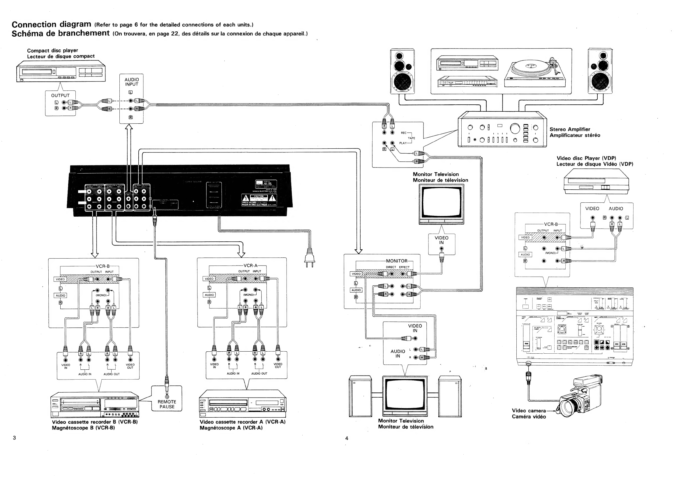
CONNECTIONS
...cc.sscssvesssecasveceseevecsesess
Panel
information...............ccceceeeeeeees
Operating
procedures...
Specifications
........ceeceeeceeeeeneeeeeeeees
Nous
vous
remercions
d‘avoir
achete
ce
produit
SANSUI
de
qualite.
Lisez
attentivement
ce
mode
d’emploi
avant
de
mettre
l'appareil
en
service.
Ceci
vous
permettra
de
vous
familliariser
avec
l'ensemble
de
ses
caractéristiques,
et
vous
serez
4
méme
de
profiter
au
maximum
de
ses
per-
formances.
*
Pour
simplifier
les
explications,
les
illustrations
peuvent
quelque-
fois
étre
différentes
des
originaux.
*
Cet
appareil
n'est
pas
concu
pour
un
usage
professionnel.
En
con-
séquence,
les
couleurs
des
barres
de
couleur
et
des
couleurs
de
fond
risquent
de
varier
suivant
la
fagon
dont
on
utilise
l'appareil.
|
FRANGAIS
PRECAUTIONS
visa
renksdes
cease
enna
wt
seaeeesaniates
Caractéristiques.........ccececccceeeeeeeee
ees
Connexions...........scceeeeeees
Indications
sur
le
panneau
Procédés
de
réglageé.........ccseseeeeee
nena
Sp6CifiCATIONS
..........ccceseceeneeeeeeeeeeees

Connection
diagram
(Refer
to
page
6
for
the
detailed
connections
of
each
units.)
Schéma
de
branchement
(0n
trouvera,
en
page
22,
des
détails
sur
la
connexion
de
chaque
appareil.)
Compact
disc
player
Lecteur
de
disque
compact
Stereo
Amplifier
Amplificateur
stéréo
Video
disc
Player
(VDP)
Lecteur
de
disque
Vidéo
(VDP)
Monitor
Television
Moniteur
de
télevision
VIDEO
AUDIO
VCR-B
OUTPUT
—
INPUT
VIDEO
O
AUDIO
(MONO}-!
MONITOR
©
@-(F
[tn
VCR-B
VCR-A
Y
|
DIRECT
EFFECT
.
OUTPUT
INPUT
OUTPUT
INPUT
OLYLLLLL
Laas
Lesa
0/fo
the
LZ
Yip?
seeA|
CHUA
@®
(mono)
VIDEO
OUT
AUDIO
IN
AUDIO
OUT
AUDIO
IN
AUDIO
OUT
cS
We
REMOTE
=
|(eSsss_L_]
=
——s
PAUSE
==
[0
0
s=s}}
Video
camera
Ly
°°
00°
geveer
=
=
Caméra
vidéo
Video
cassette
recorder
B
(VCR-B)
Video
cassette
recorder
A
(VCR-A)
Monitor
Television
—
Magnétoscope
B
(VCR-B)
Magnétoscope
A
(VCR-A)
__
Moniteur
de
télevision

Precautions
Fa
sa
i
ee
ee
*
Bear
in
mind
the
following
points.
Power
plug
When
disconnecting
the
power
cord
from
the
power
outlet,
always
take
hold
of
the
plug,
and
not
the
wire,
and
pull
free.
Never
connect
or
disconnect
the
power
plug
with
wet
hands
since
you
may
receive
an
electric
shock.
*
Remember
to
disconnect
the
power
plug
from
the
power
outlet
when
you
do
not
intend
to
use
the
unit
for
a
prolonged
period
of
time.
Do
not
remove
the
case
and
bottom
panel
Any
inspections
or
adjustments
inside
the
unit
may
lead
to
malfunc-
tions
and
electric
shocks.
Do
not
touch
any
of
the
inside
parts.
SAN-
SUI’s
warranty
is
not
effective
if
a
deterioration
in
the
unit’s
performance
results
from
remodeling
inside.
Installation
precautions
Do
not
install
the
unit
in
any
of
the
following
locations
since
this
may
result
in
a
deterioration
in
performance
or
malfunction:
*
Locations
exposed
to
direct
sunlight
or
near
objects
radiating
heat
such
as
heating
appliances.
*
Locations
exposed
to
moisture
or
humidity.
*
Locations
with
poor
ventilation
exposed
to
dust
and
dirt.
*
Locations
which
are
unstable
and
not
perfectly
flat
or
which
are
susceptible
to
vibration.
*
On
top
of
ahigh
power
output
amplifier,
audio
components
or
any
other
product
which
radiates
heat.
Do
not
wipe
with
thinners
Wipe
the
panels
and
case
from
time
to
time with
a
soft
cloth.
Using
any
kind
of
thinner,
alcohol
or
volatile
liquid
will
mar
the
surface,
cause
blotching
on
the
exterior
and
erase
the
markings
and
should
there-
fore
be
avoided.
Do
not
use
insecticide
sprays
in
the
vicinity.
A
A
a,
MAE
MS
PP
M8
Mt
The
color
TV
broadcasting
formats
employed
through-
out
the
world
include
“NTSC”,
““PAL’’
and
‘“SECAM”’.
Because
this
unit
is
designed
specifically
for
‘““NTSC”’,
it
cannot
be
used
in
areas
where
other
formats.are
used
or
connected
to
a
VCR
which
employs
another
format.
Fe
pa
dy
steht
sieneithmntaetentnenentaienimalaatael
Features
sh
a
aes
Color
Wipe
Function
By
using
22
wipe
patterns
and
8
background
colors,
you
can
trim
or
wipe
out
various
portions
of
the
picture.
Also,
by
using
a
square
pattern,
you
can
move
the
preset
wipe
pat-
tern
with
the
positioner,
enabling
you,
for
example,
to
following
the
movement
of
a
subject
while
keeping
the
picture
trimmed.
Video
Art
Functions
You
can
create
artistic
pictures
by
adding
various
color
changes
to
the
original
picture.
You
can
create
video
art
from
a
recorded
video
tape
or
a
video
tape
made
using
a
video
camera.
Also,
you
can
add
a
completely
new
dimension
to
your
old
tapes.
2-System
Monitor
Output
This
unit
is
provided
with
a
2-system
monitor
output
which
enables
you
to
monitor
original
video
and
effect
video
using
two
monitor
tel-
evisions.
Background
Color
Generator
You
can
combine
a
background
color
such
as
white,
black,
yellow,
cyan,
green,
magenta,
red,
or
blue,
with
a
wipe
function
or
fader
func-
tion,
or
set
the
screen
to
any
desired
color
and
listen
to
music.
Color
Bar
Generator
By
using
the
built-in
color
bar
generator,
you
can
perform
color
ad-
justment
of
a
monitor
television
or
make
a
color
check
of
a
video
tape.
Color
AV
Auto
Fader
Function
You
can
perform
auto
fade-in
or
auto
fade-out
using
colors
selected
from
a
total
of
8
background
colors.
Color
Corrector
Function
This
function
enables
you
to
color-compensate
tapes
which
have
poor
color
balance
due
to
an
incorrect
white
balance
setting
when
using
a
video
camera,
or
to
change
the
color
balannce
of
the
video
source
and
create
a
sepia
tone,
etc.
Enhancer
The
unit
contains
an
enhancer
with
a
noise
cut
switch
which
shar-
pens
the
contours
of
the
video
image
during
dubbing
or
editing
in
order
to
reduce
degradation
of
picture
quality.
You
can
also
use
the
en-
hancer
during
playback
to
provide
a
sharp
picture.
Time
Counter
The
unit
contains
a
time
counter
which
is
convenient
for
editing.
This
time
counter
displays
cut
time
and
also
recording/playback
time.
It
can
be
switched
between
time
count
and
lap
time.
Audio
Mixing
Function
This
function
enables
you
to
add
sound
effects,
such
the
twittering
of
birds
or
the
gurgling
of
a
river,
to
a
tape
made
using
a
video
camera,
or
to
insert
a-narration
using
a
microphone.
In
this
way
you
Can
Cre-
ate
BGV
(background
video)
tapes
or
perform
effective
tape
editing.
EXT.
PROCESSOR
Terminal
.
By
connecting
a
character
generator,
a
video
processor
such
as
a
wide
video
teloper
or
a
persona!
computer,
to
this
terminal,
you
can
su-
perimpose
titles
or
pictures
on
the
screen.
Camera
Terminal
The
unit
is
provided
with
a
camera
terminal
to
enable
it
to
be
directly
connected
to
a
VHS
type
video
camera.
:
:
:
:
i
F
;
4
PARAS
NT
SS
TIONED
AL
POT
Ree
ERE
ee
SER
et
TT
ER
IN
Se
ETF
NE
eR
SRT
OT
SL
PTT
Se
eI
eT
ee
EE
REST
ON
Le
eae
ee
SPIT

Gonnections.......
—.<
- -
= —
—
=.
ee
Refer
to
page
3
connection
diagram
as
you
read
the
following.
Connection
precautions
When
connecting,
either
disconnect
the
power
plug
from
the
pow-
er
outlet
or
turn
off
the
unit's
power
using
the
POWER
switch.
*
Before
connecting,
read
through
the
Operating
Instructions
of
the
other
components
which
will
be
connected
to
this
unit.
*
When
making
connections,
refer
to
the
illustrations
and
be
sure
to
connect
the
““IN’’,
“OUT”,
and
‘’L’’,
‘’R’’
terminals
correctly.
*
Insert
the
plugs
securely.
Improper
connection
can
lead
to
the
generation
of
noise.
*
The
input
and
output
terminals
of
this
unit
are
color
coded
as
shown
below.
White:
Left
(L)
channel
audio
signal
terminal
Red:
Right
(R)
channel
audio
signal
terminal
Yellow:
This
is
a
video
signal
terminal.
Connect
a
VCR
coaxial
cable
(750)
to
it.
If
an
audio
pin
plug
cord
is
used,
the
video
sig-
nals
(picture)
may
sometimes
be
degraded.
AC
outlets
(UNSWITCHED)
This
unit
is
provided
with
auxiliary
AC
outlets
which
are
handy
for
connecting
a
video
cassette
recorder
or
tape
deck
to
supply
power
to
these
units.
It
provides
power
continuously,
regardless
of
whether
the
power
switch
is
ON
or
OFF.
The
maximum
capacity
of
these
power
outlets
are
250W.
Do
not
attempt
to
exceed
this
capacity
as
this
is
very
dangerous.
Before
connecting
equipment
to
it,
verify
the
rated
power
consumption
of
the
equipment.
e
A
high
voltage
flows
to
the
AC
outlets
and
so
hairpins
or
other
metal
objects
must
not
be
inserted
since
this
will
result
in
an
electric
shock.
Small
children
should
not
be
allowed
to
play
with
these
outlets.
Connecting
unit
to
monitor
television
This
unit
is
provided
with
a
DIRECT
MONITOR
output
terminal
and
an
EFFECT
MONITOR
output
terminal,
enabling
you
to
connect
two
monitor
televisions
to
it.
DIRECT
MONITOR:
This
terminal
is
used
for
outputting
original
video
and
audio
which
was
input
to
the
unit.
EFFECT
MONITOR:
This
terminal
is
used
for
outputting
video
and
audio
to
which
has
been
added
various
effects
by
the
processor
function
of
the
unit.
Connect
the
VIDEO
terminal
to
the
video
input
terminal
of
the
moni-
tor
television
using
a
coaxial
connecting
cable.
Connect
the
AUDIO
terminals
to
the
TAPE
PLAY
terminals
on
the
stereo
amplifier,
or
the
AUDIO
IN
terminals
of
a
monitor
television
which
is
provided
with
a
stereo
amplifier,
using
a
pin
plug
cord.
VCR
connection
By
connecting
three
VCR
units
to
terminals
VCR-A,
and
-B,
respec-
tively,
you
can
perform
playback, recording
and
mutual
dubbing.
Connect
the
output
terminals
of
the
VCR
to
the
VCR
INPUT
termi-
nals
of
this
unit,
and
connect
the
input
terminals
of
the
VCR
to
the
VCR
OUTPUT
terminals
of
this
unit.
Correctly
connect
the
video
terminal
(yellow)
and
audio
terminals
(white
and
red)
so
that
the
colors
on
the
cord
match
the
colors
on
the
terminals.
*
Connect
the
audio
output
of
a
monaural
type
VCR
to
the
white
L
(MONO)
terminal
on
the
unit.
*
If
you
connect
a
pin
plug
to
the
video
input
(VIDEO
IN)
or
the
au-
dio
input
(AUDIO
IN)
of
a
VCR
to
make
a
video
recording,
it
may
be
necessary,
depending
upon
the
particular
VCR
which
is
used,
to
set
the
input
switch
to
the
external
input
side.
With
some
types
of
VCR,
simply
inserting
the
pin
plug
will
cause
the
input
to
be
switched
to
the
external
input.
There
are
also
some
types
of
VCR
which,
when
connected,
automatically
cut
off
the
signals
from
the
television
tuner
in
the
unit,
thus
preventing
a
television
broad-
cast
from
being
recorded.
For
details,
read
the
instruction
manual
of
the
VCR
which
you
are
using.
VDP
(video
disc
player)
connection
Connect
the
video
and
audio
terminals
of
the
VDP
to
the
VCR-A
or
B
INPUT
terminals
at
the
rear
of
the
unit.
Connecting
AUDIO
INPUT
terminals
You
can
connect
a
piece
of
audio
equipment
to
the
AUDIO
INPUT
terminals,
and
use
the
program
source
from
the
audio
equipment
as
a
sound
mixing
or
background
video audio
source.
When
connecting
a
stereo
amplifier:
By
connecting
a
stereo
amplifi-
er
to
the
AUDIO
INPUT
terminals,
you
can
use
a
program
source
connected
to
the
stereo
amplifier,
such
as
a
record
player,
com-
pact
disc
player,
tuner,
or
cassette
deck,
as
an
audio
source
for
this
unit.
;
Connect
the
TAPE
REC
terminals
of
the
stereo
amplifier
to
the
AU-
DIO
INPUT
terminals
of
this
unit
using
a
pin
plug
cord,
When
directly
connecting
a
compact
disc
player
or
tuner,
etc.:
Con-
nect
the
OUTPUT
terminals
of
th
equipment
to
be
connected,
to
the
AUDIO
INPUT
terminals
of
this
unit
using
a
pin
plug
cord.
IMPORTANT
Before
connecting
the
power
plug
This
unit's
voltage
has
been
preset
to
AC
120V,
220V,
or
240V
in
order
to
match
that
of
the
area
in
which
the
unit
is
sold.
Before
con-
necting
the
power
plug
to
an
electrical
outlet,
check
to
be
sure
that
the
unit
is
set
to
the
proper
voltage
for
your
area.
If
the
voltage
of
the
unit
is
improperly
set,
fire
hazard
or
damage
to
the
unit
may
result.
If
you
find
that
the
unit
is
not
set
to
the
proper
voltage
for
your
area,
follow
the
instructions
listed
below:
*®
On
units
not
equipped
with
a
voltage
selector
Some
units
are
not
provided
with
a
voltae
selector
due
to
laws
and
ordinances
in
the
areas
in
which
they
are
sold;
these
units
have
been
preset
to
a
specific
voltage.
If
you
wish
to
use
the
unit
in
an
area
with
a
differing
voltage,
consult
your
nearest
Sansui
Service
Station,
or
the
dealer
where
you
purchased
the
unit.
©
Units
with
120V/220V/240V
VOLTAGE
SELECTOR
switch
These
units
are
set
at
either
120V,
220V
or
240V
with
the
VOL-
TAGE
SELECTOR
switch.
To
change
the
voltage,
use
a
minus
screwdriver
or
similar
device
to
slide
the
switch.
|
|
‘
|
|
‘

Precautions
*
Bear
in
mind
the
following
points.
Power
plug
When
disconnecting
the
power
cord
from
the
power
outlet,
always
take
hold
of
the
plug,
and
not
the
wire,
and
pull
free.
Never
connect
or
disconnect
the
power
plug
with
wet
hands
since
you
may
receive
an
electric
shock.
*
Remember
to
disconnect
the
power
plug
from
the
power
outlet
when
you
do
not
intend
to
use
the
unit
for
a
prolonged
period
of
time.
Do
not
remove
the
case
and
bottom
panel
Any
inspections
or
adjustments
inside
the
unit
may
lead
to
malfunc-
tions
and
electric
shocks.
Do
not
touch
any
of
the
inside
parts.
SAN-
SUI's
warranty
is
not
effective
if
a
deterioration
in
the
unit's
performance
results
from
remodeling
inside.
Installation
precautions
Do
not
install
the
unit
in
any
of
the
following
locations
since
this
may
result
in
a
deterioration
in
performance
or
malfunction:
*
Locations
exposed
to
direct
sunlight
or
near
objects
radiating
heat
such
as
heating
appliances.
*
Locations
exposed
to
moisture
or
humidity.
*
Locations
with
poor
ventilation
exposed
to
dust
and
dirt.
*
Locations
which
are
unstable
and
not
perfectly
flat
or
which
are
susceptible
to
vibration.
*
Qn
top
of
ahigh
power
output
amplifier,
audio
components
or
any
other
product
which
radiates
heat.
Do
not
wipe
with
thinners
Wipe
the
panels
and
case
from
time
to
time
with
a
soft
cloth.
Using
any
kind
of
thinner,
alcohol
or
volatile
liquid
will
mar
the
surface,
cause
blotching
on
the
exterior
and
erase
the
markings
and
should
there-
fore
be
avoided.
Do
not
use
insecticide
sprays
in
the
vicinity.
a,
APS
MP
SOE
MA
S08
SPI
AE
EH
SRE
AL
The
color
TV
broadcasting
formats
employed
through-
out
the
world
include
‘““NTSC”’,
““PAL”’
and
‘‘SECAM”’.
Because
this
unit
is
designed
specifically
for
“NTSC”,
it
cannot
be
used
in
areas
where
other
formats.are
used
or
connected
to
a
VCR
which
employs
another
format.
MT
MRT
A
A
SME
ET
ITT
BE
Features
Color
Wipe
Function
;
By
using
22
wipe
patterns
and
8
background
colors,
you
can
trim
or
wipe
out
various
portions
of
the
picture.
;
Also,
by
using
a
square
pattern,
you
can
move
the
preset
wipe
pat-
tern
with
the
positioner,
enabling
you,
for
example,
to
following
the
movement
of
a
subject
while
keeping
the
picture
trimmed.
Video
Art
Functions
You
can
create
artistic
pictures
by
adding
various
color
changes
to
the
original
picture.
You
can create
video
art
from
a
recorded
video
tape
or
a
video
tape
made
using
a
video
camera.
Also,
you
can
add
a
completely
new
dimension
to
your
old
tapes.
2-System
Monitor
Output
This
unit
is
provided
with
a
2-system
monitor
output
which
enables
you
to
monitor
original
video
and
effect
video
using
two
monitor
tel-
evisions.
Background
Color
Generator
You
can
combine
a
background
color
such
as
white,
black,
yellow,
cyan,
green,
magenta,
red,
or
blue,
with
a
wipe
function
or
fader
func-
tion,
or
set
the
screen
to
any
desired
color
and
listen
to
music.
Color
Bar
Generator
By
using
the
built-in
color
bar
generator,
you
can
perform
color
ad-
justment
of
a
monitor
television
or
make
a
color
check
of
a
video
tape.
Color
AV
Auto
Fader
Function
You
can
perform
auto
fade-in
or
auto
fade-out
using
colors
selected
from
a
total
of
8
background
colors.
Color
Corrector
Function
This
function
enables
you
to
color-compensate
tapes
which
have
poor
color
balance
due
to
an
incorrect
white
balance
setting
when
using
a
video
camera,
or
to
change
the
color
balannce
of
the
video
source
and
create
a
sepia
tone,
etc.
Enhancer
The
unit
contains
an
enhancer
with
a
noise
cut
switch
which
shar-
pens
the
contours
of
the
video
image
during
dubbing
or
editing
in
order
to
reduce
degradation
of
picture
quality.
You
can
also
use
the
en-
hancer
during
playback
to
provide
a
sharp
picture.
Time
Counter
The
unit
contains
a
time
counter
which
is
convenient
for
editing.
This
time
counter
displays
cut
time
and
also
recording/playback
time.
It
can
be
switched
between
time
count
and
lap
time.
Audio
Mixing
Function
This
function
enables
you
to
add
sound
effects,
such
the
twittering
of
birds
or
the
gurgling
of
a
river,
to
a
tape
made
using
a
video
camera,
or
to
insert
a-narration
using
a
microphone.
!n
this
way
you
can
cre-
ate
BGV
(background
video)
tapes
or
perform
effective
tape
editing.
EXT.
PROCESSOR
Terminal
.
By
connecting
a
character
generator,
a
video
processor
such
as
a
wide
video
teloper
or
a
personal
computer,
to
this
terminal,
you
can
su-
perimpose
titles
or
pictures
on
the
screen.
Camera
Terminal
The
unit
is
provided
with
a
camera
terminal
to
enable
it
to
be
directly
connected
to
a
VHS
type
video
camera.
-
HSIIONG
-
i
}
j
:
|
i
i
4
i
:
4
i

COnmN@CTIONS
=.
-
>.<
=.
=
he
=e
ee
ee
Refer
to
page
3
connection
diagram
as
you
read
the
following.
Connection
precautions
When
connecting,
either
disconnect
the
power
plug
from
the
pow-
er
outlet
or
turn
off
the
unit’s
power
using
the
POWER
switch.
*
Before
connecting,
read
through
the
Operating
Instructions
of
the
other
components
which
will
be
connected
to
this
unit.
*
When
making
connections,
refer
to
the
illustrations
and
be
sure
to
connect
the
“‘IN’’,
“OUT”,
and
‘“‘L"’,
‘’R’’
terminals
correctly.
*
Insert
the
plugs
securely.
Improper
connection
can
lead
to
the
generation
of
noise.
*
The
input
and
output
terminals
of
this
unit
are
color
coded
as
shown
below.
White:
Left
(L}
channel
audio
signal
terminal
Red:
Right
(R)
channel
audio
signal
terminal
Yellow:
This
is
a
video
signal
terminal.
Connect
a
VCR
coaxial
cable
(759)
to
it.
If
an
audio
pin
plug
cord
is
used,
the
video
sig-
nals
(picture)
may
sometimes
be
degraded.
AC
outlets
(UNSWITCHED)
This
unit
is
provided
with
auxiliary
AC
outlets
which
are
handy
for
connecting
a
video
cassette
recorder
or
tape
deck
to
supply
power
to
these
units.
It
provides
power
continuously,
regardless
of
whether
the
power
switch
is
ON
or
OFF.
The
maximum
capacity
of
these
power
outlets
are
250W.
Do
not
attempt
to
exceed
this
capacity
as
this
is
very
dangerous.
Before
connecting
equipment
to
it,
verify
the
rated
power
consumption
of
the
equipment.
¢
A
high
voltage
flows
to
the
AC
outlets
and
so
hairpins
or
other
metal
objects
must
not
be
inserted
since
this
will
result
in
an
electric
shock.
Smail
children
should
not
be
allowed
to
play
with
these
outlets.
Connecting
unit
to
monitor
television
This
unit
is
provided
with
a
DIRECT
MONITOR
output
terminal
and
an
EFFECT
MONITOR
output
terminal,
enabling
you
to
connect
two
monitor
televisions
to
it.
DIRECT
MONITOR:
This
terminal
is
used
for
outputting
original
video
and
audio
which
was
input
to
the
unit.
EFFECT
MONITOR:
This
terminal
is
used
for
outputting
video
and
audio
to
which
has
been
added
various
effects
by
the
processor
function
of
the
unit.
Connect
the
VIDEO
terminal
to
the
video
input
terminal
of
the
moni-
tor
television
using
a
coaxial
connecting
cable.
Connect
the
AUDIO
terminals
to
the
TAPE PLAY
terminals
on
the
stereo
amplifier,
or
the
AUDIO
IN
terminals
of
a
monitor
television
which
is
provided
with
a
stereo
amplifier,
using
a
pin
plug
cord.
VCR
connection
By
connecting
three
VCR
units
to
terminals
VCR-A,
and
-B,
respec-
tively,
you
can
perform
playback,
recording
and
mutual
dubbing.
Connect
the
output
terminals
of
the
VCR
to
the
VCR
INPUT
termi-
nals
of
this
unit,
and
connect
the
input
terminals
of
the
VCR
to
the
VCR
OUTPUT
terminals
of
this
unit.
Correctly
connect
the
video
terminal
(yellow)
and
audio
terminals
(white
and
red)
so
that
the
colors
on
the
cord
match
the
colors
on
the
terminals.
*
Connect
the
audio
output
of
a
monaural
type
VCR
to
the
white
L
(MONO)
terminal
on
the
unit.
*
|f
you
connect
a
pin
plug
to
the
video
input
(VIDEO
IN)
or
the
au-
dio
input
(AUDIO
IN)
of
a
VCR
to
make
a
video
recording,
it
may
be
necessary,
depending
upon
the
particular
VCR
which
is
used,
to
set
the
input
switch
to
the
external
input
side.
With
some
types
of
VCR,
simply
inserting
the
pin
plug
will
cause
the
input
to
be
switched
to
the
external
input.
There
are
also
some
types
of
VCR
which,
when
connected,
automatically
cut
off
the
signals
from
the
television
tuner
in
the
unit,
thus
preventing
a
television
broad-
cast
from
being
recorded.
For
details,
read
the
instruction
manual
of
the
VCR
which
you
are
using.
VDP
(video
disc
player)
connection
Connect
the
video
and
audio
terminals
of
the
VDP
to
the
VCR-A
or
B
INPUT
terminals
at
the
rear
of
the
unit.
Connecting
AUDIO
INPUT
terminals
You
can
connect
a
piece
of
audio
equipment
to
the
AUDIO
INPUT
terminals,
and
use
the
program
source
from
the
audio
equipment
as
a
sound
mixing
or
background
video
audio
source.
When
connecting
a
stereo
amplifier:
By
connecting
a
stereo
amplifi-
er
to
the
AUDIO
INPUT
terminals,
you
can use
a
program
source
connected
to
the
stereo
amplifier,
such
as
a
record
player,
com-
pact
disc
player,
tuner,
or
cassette
deck,
as
an
audio
source
for
this
unit.
:
Connect
the
TAPE
REC
terminals
of
the
stereo
amplifier
to
the
AU-
DIO
INPUT
terminals
of
this
unit
using
a
pin
plug
cord.
When
directly
connecting
a
compact
disc
player
or
tuner,
etc.:
Con-
nect
the
OUTPUT
terminals
of th
equipment
to
be
connected,
to
the
AUDIO
INPUT
terminals
of
this
unit
using
a
pin
plug
cord.
IMPORTANT
Before
connecting
the
power
plug
This
unit’s
voltage
has
been
preset
to
AC
120V,
220V,
or
240V
in
order
to
match
that
of
the
area
in
which
the
unit
is
sold.
Before
con-
necting
the
power
plug
to
an
electrical
outlet,
check
to
be
sure
that
the
unit
is
set
to
the
proper
voltage
for
your
area.
If
the
voltage
of
the
unit
is
improperly
set,
fire
hazard
or
damage
to
the
unit
may
result.
If
you
find
that
the
unit
is
not
set
to
the
proper
voltage
for
your
area,
follow
the
instructions
listed
below:
*
On
units
not
equipped
with
a
voltage
selector
Some
units
are
not
provided
with
a
voltae
selector
due
to
jaws
and
ordinances
in
the
areas
in
which
they
are
sold;
these
units
have
been
preset
to
a
specific
voltage.
!f
you
wish
to
use
the
unit
in
an
area
with
a
differing
voltage,
consult
your
nearest
Sansui
Service
Station,
or
the
dealer
where
you
purchased
the
unit.
©
Units
with
120V/220V/240V
VOLTAGE
SELECTOR
switch
These
units
are
set
at
either
120V,
220V
or
240V
with
the
VOL-
TAGE
SELECTOR
switch.
To
change
the
voltage,
use
a
minus
screwdriver
or
similar
device
to
slide
the
switch.
VOLTAGE
SELECTOR
“VOLTAGE
SELECTOR
O
OP
ao
|
!
:

Precautions
*
Bear
in
mind
the
following
points.
Power
plug
When
disconnecting
the
power
cord
from
the
power
outlet,
always
take
hold
of
the
plug,
and
not
the
wire,
and
pull
free.
Never
connect
or
disconnect
the
power
plug
with
wet
hands
since
you
may
receive
an
electric
shock.
*
Remember
to
disconnect
the
power
plug
from
the
power
outlet
when
you
do
not
intend
to
use
the
unit
for
a
prolonged
period
of
time.
Do
not
remove
the
case
and
bottom
panel
Any
inspections
or
adjustments
inside
the
unit
may
lead
to
malfunc-
tions
and
electric
shocks.
Do
not
touch
any
of
the
inside
parts.
SAN-
SUI’s
warranty
is
not
effective
if
a
deterioration
in
the
unit’s
performance
results
from
remodeling
inside.
Installation
precautions
Do
not
install
the
unit
in
any
of
the
following
locations
since
this
may
result
in
a
deterioration
in
performance
or
malfunction:
*
Locations
exposed
to
direct
sunlight
or
near
objects
radiating
heat
such
as
heating
appliances.
*
Locations
exposed
to
moisture
or
humidity.
*
Locations
with
poor
ventilation
exposed
to
dust
and
dirt.
*
Locations
which
are
unstable
and
not
perfectly
flat
or
which
are
susceptible
to
vibration.
*
On
top
of
ahigh
power
output
amplifier,
audio
components
or
any
other
product
which
radiates
heat.
Do
not
wipe
with
thinners
Wipe
the
panels
and
case
from
time
to
time
with
a
soft
cloth.
Using
any
kind
of
thinner,
alcohol
or
volatile
liquid
will
mar
the
surface,
cause
blotching
on
the
exterior
and
erase
the
markings
and
should
there-
fore
be
avoided.
Do
not
use
insecticide
sprays
in
the
vicinity.
cd
MRE
I
8
ER MT
AP
The
color
TV
broadcasting
formats
employed
through-
out
the
world
include
‘‘NTSC”’,
‘’PAL’’
and
‘‘SECAM”.
Because
this
unit
is
designed
specifically
for
‘NTSC’,
it
cannot
be
used
in
areas
where
other
formats.are
used
or
connected
to
a
VCR
which
employs
another
format.
BOO
IN
NE
MN,
Features.
Color
Wipe
Function
:
By
using
22
wipe
patterns
and
8
background
colors,
you
can
trim
or
wipe
out
various
portions
of
the
picture.
Also,
by
using
a
square
pattern,
you
can
move
the
preset
wipe
pat-
tern
with
the
positioner,
enabling
you,
for
example,
to
following
the
movement
of
a
subject
while
keeping
the
picture
trimmed.
Video
Art
Functions
You
can
create
artistic
pictures
by
adding
various
color
changes
to
the
original
picture.
You
can
create
video
art
from
a
recorded
video
tape
or
a
video
tape
made
using
a
video
camera.
Also,
you
can
add
a
completely
new
dimension
to
your
old
tapes.
2-System
Monitor
Output
This
unit
is
provided
with
a
2-system
monitor
output
which
enables
you
to
monitor
original
video
and
effect
video
using
two
monitor
tel-
evisions.
Background
Color
Generator
You
can
combine
a
background
color
such
as
white,
black,
yellow,
cyan,
green,
magenta,
red,
or
blue,
with
a
wipe
function
or
fader
func-
tion,
or
set
the
screen
to
any
desired
color
and
listen
to
music.
Color
Bar
Generator
By
using
the
built-in
color
bar
generator,
you
can
perform
color
ad-
justment
of
a
monitor
television
or
make
a
color
check
of
a
video
tape.
Color
AV
Auto
Fader
Function
You
can
perform
auto
fade-in
or
auto
fade-out
using
colors
selected
from
a
total
of
8
background
colors.
Color
Corrector
Function
This
function
enables
you
to
color-compensate
tapes
which
have
poor
color
balance
due
to
an
incorrect
white
balance
setting
when
using
a
video
camera,
or
to
change
the
color
balannce
of
the
video
source
and
create
a
sepia
tone,
etc.
Enhancer
The
unit
contains
an
enhancer
with
a
noise
cut
switch
which
shar-
pens
the
contours
of
the
video
image
during
dubbing
or
editing
in
order
to
reduce
degradation
of
picture
quality.
You
can
also
use
the
en-
hancer
during
playback
to
provide
a
sharp
picture.
Time
Counter
The
unit
contains
a
time
counter
which
is
convenient
for
editing.
This
time
counter
displays
cut
time
and
also
recording/playback
time.
It
can
be
switched
between
time
count
and
lap
time.
Audio
Mixing
Function
This
function
enables
you
to
add
sound
effects,
such
the
twittering
of
birds
or
the
gurgling
of
a
river,
to
a
tape
made
using
a
video
camera,
or
to
insert
a-narration
using
a
microphone.
!n
this
way
you
can
cre-
ate
BGV
(background
video)
tapes
or
perform
effective
tape
editing.
EXT.
PROCESSOR
Terminal
:
By
connecting
a
character
generator,
a
video
processor
such
as
a
wide
video
teloper
or
a
personal
computer,
to
this
terminal,
you
can
su-
perimpose
titles
or
pictures
on
the
screen.
Camera
Terminal
The
unit
is
provided
with
a
camera
terminal
to
enable
it
to
be
directly
connected
to
a
VHS
type
video
camera.
“HSKTONA

Connections
0
<5
ee
=
ee
8
Refer
to
page
3
connection
diagram
as
you
read
the
following.
Connection
precautions
When
connecting,
either
disconnect
the
power
plug
from
the
pow-
er
outlet
or
turn
off
the
unit’s
power
using
the
POWER
switch.
*
Before
connecting,
read
through
the
Operating
Instructions
of
the
other
components
which
will
be
connected
to
this
unit.
*
When
making
connections,
refer
to
the
illustrations
and
be
sure
to
connect
the
“IN’’,
““OUT”,
and
‘’L’’,
‘’R’’
terminals
correctly.
*
Insert
the
plugs
securely.
Improper
connection
can
lead
to
the
generation
of
noise.
*
The
input
and
output
terminals
of
this
unit
are
color
coded
as
shown
below.
White:
Left
(L)
channel
audio
signal
terminal
Red:
Right
(R)
channel
audio
signal
terminal
Yellow:
This
is
a
video
signal
terminal.
Connect
a
VCR
coaxial
cable
(759)
to
it.
If
an
audio
pin
plug
cord
is
used,
the
video
sig-
nals
(picture)
may
sometimes
be
degraded.
AC
outlets
(UNSWITCHED)
This
unit
is
provided
with
auxiliary
AC
outlets
which
are
handy
for
connecting
a
video
cassette
recorder
or
tape
deck
to
supply
power
to
these
units.
It
provides
power
continuously,
regardless
of
whether
the
power
switch
is
ON
or
OFF.
The
maximum
capacity
of
these
power
outlets
are
250W.
Do
not
attempt
to
exceed
this
capacity
as
this
is
very
dangerous.
Before
connecting
equipment
to
it,
verify
the
rated
power
consumption
of
the
equipment.
¢
A
high
voltage
flows
to
the
AC
outlets
and
so
hairpins
or
other
metal
objects
must
not
be
inserted
since
this
will
result
in
an
electric
shock.
Small
children
should
not
be
allowed
to
play
with
these
outlets.
Connecting
unit
to
monitor
television
This
unit
is
provided
with
a
DIRECT
MONITOR
output
terminal
and
an
EFFECT
MONITOR
output
terminal,
enabling
you
to
connect
two
monitor
televisions
to
it.
DIRECT
MONITOR:
This
terminal
is
used
for
outputting
original
video
and
audio
which
was
input
to
the
unit.
EFFECT
MONITOR:
This
terminal
is
used
for
outputting
video
and
audio
to
which
has
been
added
various
effects
by
the
processor
function
of
the
unit.
Connect
the
VIDEO
terminal
to
the
video
input
terminal
of
the
moni-
tor
television
using
a
coaxial
connecting
cable.
Connect
the
AUDIO
terminals
to
the
TAPE
PLAY
terminals
on
the
stereo
amplifier,
or
the
AUDIO
IN
terminals
of
a
monitor
television
which
is
provided
with
a
stereo
amplifier,
using
a
pin
plug
cord.
VCR
connection
By
connecting
three
VCR
units
to
terminals
VCR-A,
and
-B,
respec-
tively,
you
can
perform
playback,
recording
and
mutual
dubbing.
Connect
the
output
terminals
of
the
VCR
to
the
VCR
INPUT
termi-
nals
of
this
unit,
and
connect
the
input
terminals
of
the
VCR
to
the
VCR
OUTPUT
terminals
of
this
unit.
Correctly
connect
the
video
terminal
(yellow)
and
audio
terminals
(white
and
red)
so
that
the
colors
on
the
cord
match
the
colors
on
the
terminals.
*
Connect
the
audio
output
of
a
monaural
type
VCR
to
the
white
L
(MONO)
terminal
on
the
unit.
*
|f
you
connect
a
pin
plug
to
the
video
input
(VIDEO
IN)
or
the
au-
dio
input
(AUDIO
IN)
of
a
VCR
to
make
a
video
recording,
it
may
be
necessary,
depending
upon
the
particular
VCR
which
is
used,
to
set
the
input
switch
to
the
external
input
side.
With
some
types
of
VCR,
simply
inserting
the
pin
plug
will
cause
the
input
to
be
switched
to
the
external
input.
There
are
also
some
types
of
VCR
which,
when
connected,
automatically
cut
off
the
signals
from
the
television
tuner
in
the
unit,
thus
preventing
a
television
broad-
cast
from
being
recorded.
For
details,
read
the
instruction
manual
of
the
VCR
which
you
are
using.
VDP
(video
disc
player)
connection
Connect
the
video
and
audio
terminals
of
the
VDP
to
the
VCR-A
or
B
INPUT
terminals
at
the
rear
of
the
unit.
Connecting
AUDIO
INPUT
terminals
You
can
connect
a
piece
of
audio
equipment
to
the
AUDIO
INPUT
terminals,
and
use
the
program
source
from
the
audio
equipment
as
a
sound
mixing
or
background
video audio
source.
When
connecting
a
stereo
amplifier:
By
connecting
a
stereo
amplifi-
er
to
the
AUDIO
INPUT
terminals,
you
can
use
a
program
source
connected
to
the
stereo
amplifier,
such
as
a
record
player,
com-
pact
disc
player,
tuner,
or
cassette
deck,
as
an
audio
source
for
this
unit.
‘
Connect
the
TAPE
REC
terminals
of
the
stereo
amplifier
to
the
AU-
DIO
INPUT
terminals
of
this
unit
using
a
pin
plug
cord.
When
directly
connecting
a
compact
disc
player
or
tuner,
etc.:
Con-
nect
the
OUTPUT
terminals
of
th
equipment
to
be
connected,
to
the
AUDIO
INPUT
terminals
of
this
unit
using
a
pin
plug
cord.
IMPORTANT
Before
connecting
the
power
plug
This
unit's
voltage
has
been
preset
to
AC
120V,
220V,
or
240V
in
order
to
match
that
of
the
area
in
which
the
unit
is
sold.
Before
con-
necting
the
power
plug
to
an
electrical
outlet,
check
to
be
sure
that
the
unit
is
set
to
the
proper
voltage
for
your
area.
If
the
voltage
of
the
unit
is
improperly
set,
fire
hazard
or
damage
to
the
unit
may
result.
lf
you
find
that
the
unit
is
not
set
to
the
proper
voltage
for
your
area,
follow
the
instructions
listed
below:
¢
On
units
not
equipped
with
a
voltage
selector
Some
units
are
not
provided
with
a
voltae
selector
due
to
jaws
and
ordinances
in
the
areas
in
which
they
are
sold;
these
units
have
been
preset
to
a
specific
voltage.
If
you
wish
to
use
the
unit
in
an
area
with
a
differing
voltage,
consult
your
nearest
Sansui
Service
Station,
or
the
dealer
where
you
purchased
the
unit.
©
Units
with
120V/220V/240V
VOLTAGE
SELECTOR
switch
These
units
are
set
at
either
120V,
220V
or
240V
with
the
VOL-
TAGE
SELECTOR
switch.
To
change
the
voltage,
use
a
minus
screwdriver
or
similar
device
to
slide
the
switch.

Connecting
video
camera
Align
the
groove
of
the
video
camera
connector
with
the
CAMERA
terminal
on
the
front
panel
of
the
unit,
then
insert
the
connector.
Also,
it
is
possible
to
remotely
start/stop
VCR
recording
when
oper-
ating
the
video
camera,
by
connecting
the
CONTROL
terminal
at
the
rear
of
this
unit
to
the
CAMERA
REMOTE
terminal
of
the
VCR,
using
the
remote
control
cord
provided
with
a
mini
jack.
*
It
is
not
possible
to
use
a
video
camera
having
a
power
consump-
tion
of
more
than
7
watts.
*
Although
it
is
possible
to
use
a
VHS
type
video
camera
directly,
the
remote
control
start/stop
operation
may
sometimes
be
reversed
depending
upon
the
video
camera
used.
*
The
CAMERA
terminal
of
this
unit
is
a
‘‘round
10-pin
J
type
ter-
minal’’.
Consequently,
when
connecting
the
unit
to
a
beta
type
video
camera
(14-pin
K
type
terminal),
it
is
necessary
to
use
a
com-
mercially
available
adapter.
Consult
with
the
shop
where
you
pur-
chased
your
unit.
*
The
CAMERA
REMOTE
terminal
on
some
VCRs
is
of
small
diamter,
which
may
prevent
the
remote
control
cord
from
being
used.
In
such
a
case,
it
is
necessary
to
use
a
3.5
dia.
2.5
dia.
conver-
sion
jack.
*
Some
VCRs
provided-with
a
CAMERA
terminal
do
not
have
a
CAMERA
REMOTE
terminal.
When
a
video
camera
is
connected
to
this
unit
it
is
not
possible
to
remotely
control
such
a
VCR.
Connecting
CONTROL
Terminal
When
using
a
VCR
which
is
provided
with
a
REMOTE
PAUSE
termi-
nal,
you
can
control
recording/pause
of
the
VCR
by
connecting
the
CONTROL
terminal
of
this
unit
to
the
REMOTE
PAUSE
terminal
of
the
VCR
using
the
control
cable
provided
with
the
unit,
and
then
us-
ing
the
control
function
of
this
unit.
For
details
of
the
control
function
of
this
unit,
refer
to
Page
14.
*
Two
control
cables
are
provided.
One
has
3.5
mm
dia.
plugs
at
both
ends,
and
the
other
has
a
3.5
mm
dia.
plug
at
one
end
and
a
2.5
mm
dia.
plug
at
the
opposite
end.
Select
one
of
these
ca-
bles
to
match
the
REMOTE
PAUSE
terminal
of
the
VCR
which
you
intend
to
use.
*
Because
some
VCRs
are
not
provided
with
a
REMOTE
PAUSE
ter-
minal,
or
use
a
different
format,
it
may
not
always
be
possible
to
control
the
VCR
with
this
unit.
Connecting
the
unit
to
an
S-XV1000
or
AV-C10
You
can
increase
the
range
of
functions
of
your
AV
system
by
con-
necting
the
unit
to
audio
center
S-XV1000
or
VC-C10,
each
of
which
is
provided
with
an
AV
sound
function
to
enable
you
to
enjoy
4-channel
sound
reproduction
with
movie
theater
or
concert
hall
real-
ism
as
well
as
an
AV
selector/mutual
dubbing
function.
Connect
the
VCR
or
VDP
to
the
S-XV1000
or
AV-C10,
and,
apart
from
when
using
a
camera,
set
the
SELECTOR/DUBBING
switches
to
VCR-A.
Also,
connect
the
monitor
television
which
is
connected
to
the
MONITOR/EFFECT
terminal,
to
the
MONITOR
OUT
terminal
of
the
S-XV1000
or
AV-C10.
Connection
example
(AV-C10)
AV-C10
H|
aooono
«--
uno
Oo
HEEB!
.
For the
Customers
This
equipment
generates
and
uses
radio
frequency
energy
and
if
not
installed
and
used
properly,
that
is,
in
strict
accordance
with
the
manufacturer's
instructions,
may
cause
interference
to
radio
and
tel-
evision
reception.
It
has
been
type
tested
and
found
to
comply
with
the
limits
for
a
Class
B
computing
device
in
accordance
with
the
specifications
in
Subpart
J
of
Part
15
of
FCC
Rules.
which
are
disigned
to
provide
reasonable
protection
against
such
interference
in
a
residential
installation.
However,
there
is
no
guarantee
that
interference
will
not
occur
in
a
particular
installation.
If
this
equipment
does
cause
interference
to
radio
or
television
reception,
which
can
be
determined
by
turning
the
equipment
off
and
on,
the
user
is
encouraged
to
try
to
correct
the
interference
by
one
or
more
of
the
following
measures:
VODEO
AUDIO
eiyuiet
reorient
the
receiving
antenna
siidteaes
relocate
this
equipment
with
respect
to
the
receiver
etree
move
this
equipment
away
from
the
receiver
Setseesh
plug
this
equipment
into
a
different
outlet
so
that
equipment
and
receiver
are
on
different
branch
circuits.
If
necessary,
the
user
should
consult
the
dealer
or
an
exprienced
ra-
dio/television
technician
for
additional
suggestions.
The
user
may
find
the
following
booklet
prepared
by
the
Federal
Communications
Com-
mission
helpful:
‘‘How
to
Identify
and
Resolve
Radio—
TV
Interfer-
ence
Problems’.
This
booklet
is
available
from
the
US
Government
Printing
Office,
Washington,
D.C.,
20402,
Stock
No.
004-000-
00345-4.

Panel
information
11
1
POWER
switch
When
this
switch
is
pressed,
power
to
the
unit
is
turned
ON,
and
the
upper
indicator
lights.
When
pressed
and
released
once
more,
pow-
er
is
turned
off.
2
SELECTOR/DUBBING
Switches
These
switches
are
used
to
select
the
desired
video
(VCR,
VDP,
video
camera,
etc.)
or
audio
(compact
disc
player,
cassette
deck,
tuner,
etc.)
source.
When
a
switch
is
pressed,
the
corresponding
indicator
will
light.
These
switches
also
have
a
dubbing
mode
select
function.
VCR-A
(VCR-A
®
VCR-B):
Press
this
switch
when
playing
back
VCR-
A
or
dubbing
from
VCR-A
to
VCR-B.
VCR-B(VCR-B
®
VCR-A):
Press
this
switch
when
playing
back
VCR-B
or
dubbing
from
VCR-B
to
VCR-A.
CAMERA
(CAMERA
®
VCR-A/B):
Press
this
switch
to
record
video
produced
using
a
video
camera
which
is
connected
to
the
unit,
or
to
monitor
a
television
screen.
AUDIO:
Press
this
switch
to
play
back
a
program
source
(FM
broad-
cast
or
compact
disc,
etc.)
from
audio
equipment
which
is
con-
nected
to
the
AUDIO
INPUT
terminals,
or
to
make
a
recording
on
a
Hi-Fi
VCR.
12
Sere,
17
16
3
Time
Counter
(TIME
COUNTER)
This
counter
counts
the
recording
time,
playback
time,
and
cut
time,
and
displays
the
time
between
1
second
and
9
hours,
59
minutes
and
59
seconds
on
an
illuminated
display.
START/STOP
Switch:
By
pressing
this
switch,
the
time
count
will
start,
and
by
pressing
it
again,
the
time
count
will
stop.
LAP/RESET
Switch:
By
pressing
this
switch
during
a
time
count,
the
lap
time
will
be
displayed.
The
time
count
will
continue
while
the
lap
time
is
displayed.
By
pressing
this
switch
once
again,
the
time
count
display
will
be
displayed
once
again.
By
pressing
this
switch
when
the
time
count
is
stopped,
the
time
count
display
will
be
reset,
and
the
display
will
revert
to
‘‘O4OOMOOS’’.
4
Enhancer
(ENHANCER)
This
is
a
delay
line
type
enhancer
function.
It
is
used
to
sharpen
outlines
which
have
been
dulled
during
dubbing.
ENHANCER
Switch:
When
this
switch
is
pressed,
the
indicator
will
light,
and
the
enhancer
function
will
operate.
When
it
is
pressed
once
again,
the
indicator
will
go
out,
and
the
enhancer
function
will
be
canceled.
ENHANCER
VOLUME:
By
sliding
this
control
upward,
contours
will
be
accentuated,
thereby
minimizing
degradation
of
the
picture
due
to
dubbing.
NOISE
CUT
Switch:
If
the
enhancer
is
set
too
high,
noise
will
be-
come
prominent
when
the
picture
is
dark.
In
such
a
case,
press
this
switch.
The
indicator
will
light
and
the
noise
component
caused
by
excessive
enhancement
will
be
reduced.

5
SOUND
MIXING
Switch
By
pressing
this
switch,
the
indicator
will
light,
and
the
sound
mix-
ing
function
which
enables
you
to
mix
the
audio
from
the
VCR
with
an
external
audio
source
will
operate.
By
pressing
the
switch
once
again,
the
indicator
will
go
out
and
the
sound
mixing
function
will
be
canceled.
During
editing,
you
can
use
this
sound
mixing
function
to
mix
effect
sound
with
the
audio
of
a
video
tape
made
using
a
camera.
6
SOUND
MIXING
VOLUME
You
can
control
the
mixing
ratio
of
the
video
source
and
audio
source
by
moving
this
control
up
or
down.
By
sliding
the
control
to
the
VIDEO
side,
the
sound
level
from
the
video
will
increase.
By
sliding
it
to
the
AUDIO
side,
the
audio
source
will
increase.
7
MIC
MIXING
Switch
When
this
switch
is
pressed,
the
indicator
will
light,
and
the
micro-
phone
mixing
function
will
be
activated,
enabling
you
to
use
a
micro-
phone
to
mix
a
narration
with
the
audio
of
a
video
source
or
another
audio
source.
By
pressing
the
switch
once
again,
the
indicator
will
go
out
and
the
microphone
mixing
function
will
be
canceled.
You
can
use
this
microphone
mixing
function
to
add
narration
to
a
tape
for
effective
editing.
8
MIC
MIXING
VOLUME
You
can
control
the
microphone
mixing
level
by
sliding
this
control
up
or
down.
By
sliding
the
contro!
to
the
SOURCE
side,
the
sound
level
from
the
video
source
or
audio
source
will
increase,
and
by
sliding
it
to
the
MIC
side,
the
sound
level
from
the
microphone
will
increase.
9
Video
Art
Control
Section
(VIDEO
ART)
Video
art
is
a
function
which
enables
you
to
create
special
effects
by
adding
a
background
color
to
bright
or
dark
portions
of
the
picture.
VIDEO
ART
Switch:
By
pressing
this
switch
‘‘ON’’,
the
indicator
will
light
and
the
video
art
function
will
be
activated.
By
pressing
it
once
again,
the
indicator
will
go
out
and
the
video
art
function
will
be
canceled.
NORMAL/REVERSE
Switch:
When
this
switch
is
pressed
to
activate
the
‘‘REV"'
mode,
the
indicator
will
light,
and
a
background
color
will
be
added
to
bright
portions
of
the
picture.
By
pressing
it
once
again,
the
indicator
will
go
out
and
color
will
be
added
to
dark
por-
tions
of
the
picture.
:
PICTURE
EFFECTOR
Control:
By
sliding
this
control,
the
range
of
the
picture
over
which
a
background
color
is
added
will
change.
10
CAMERA
Terminal
This
is
a
camera
terminal
to
which
a
VHS
type
camera
can
be
direct-
ly
connected.
It
enables
special
effects
such
as
video
art,
color
wipe,
trimming,
and
color
fading,
etc.,
to
be
added
to
camera
video
(for
details,
see
page
7).
It
supplies
power
to
the
video
camera
and
also
inputs
video,
audio
and
remote
control
signals
from
the
camera.
*
Before
connecting
or
disconnecting
the
video
camera,
be
sure
to
first
turn
off
the
POWER
switch.
The
audio
is
monaural.
It
is
not
possible
to
observe
the
reproduced
image
from
the
VCR
on
the
electronic
viewfinder.
11
AV
AUTO
FADER
Function
Fade-in
means
the
gradual
appearance
of
a
picture
on
the
screen
start-
ing
with
a
blank
screen.
Conversely,
fade-out
means
the
gradual
dis-
appearance
of
a
picture
from
the
screen.
Fade-in
or
fade-out
will
automatically
take
place
when
the
corresponding
switch
is
pressed.
The
fade
duration
can
be
freely
set
between
about
1
second
and
about
10
seconds.
.
You
can
also
connect
a
video
camera
to
the
unit
and
control
the
auto
fader
using
the
switch
on
the
camera.
AV
AUTO
FADER
Switch:
By
pressing
this
switch
‘’ON”’,
the
indi-
cator
will
light
and
the
auto
fader
will
be
activated.
By
pressing
the
switch
again,
the
auto
fader
function
will
be
canceled.
FADE
DURATION
Control:
By
using
this
control,
you
can
freely
vary
the
fade-in
and
fade-out
duration
between
about
1
seconds
and
about
10
seconds.
IN/OUT
(START/PAUSE)
Switch:
You
can
perform
fade-in
or
fade-
out
using
this
switch.
If
you
press
this
switch
while
the
switch
indicator
is
lit,
the
video
and
audio
will
simultaneously
fade
out.
If
you
press
it
while
the
switch
indicator
is
out,
the
audio
will
fade
in.
While
the
fader
is
operating,
the
indicator
will
flash.
*
When
the
unit
is
connected
to
the
recording
side
VCR
by
a
cable,
you
can
synchronize
fader
operation
with
the
VCR
recording
oper-
ation
by
means
of
the
IN/OUT
(START/PAUSE)
switch.
*
The
operation
of
part
of
the
AV
auto
fader
function
varies
depend-
ing
upon
the
position
of
the
FADER
(AUTO/MANUAL)
switch
at
the
back
of
the
unit.
For
details,
refer
to
the
section
‘‘Using
the
Control
Function’’
on
Page
14.
12
BACKGROUND
COLOR
Switches
By
pressing
these
switches,
you
can
output
up
to
8
background
colors,
namely
YELLOW,
CYAN,
GREEN,
MAGENTA,
RED,
BLUE,
WHITE,
and
BLACK.
When
a
switch
is
pressed,
the
corresponding
indicator
will
fight.
These
background
colors
can
be
used
effectively
for
color
wipe,
color
fading,
and
video
art.
13
COLOR
BAR
Switch
By
pressing
this
switch
when
the
picture
is
wiped
out,
color
bars
can
be
output.
Color
bars
are
convenient
for
performing
a
color
check
of
a
monitor
television
or
for
recording
onto
the
beginning
of
a
tape
in
order
to
make
a
color
check
of
the
tape.
You
can
also
use
color
bars
with
color
wipe,
color
fading,
or
video
art
to
obtain
special
effects.
14
COLOR
CORRECTOR
Section
By
using
this
section,
you
can
compensate
for
tapes
with
poor
color
balance
due
to
an
incorrect
white
balance
setting
error
or
an
incor-
rect
indoor/outdoor
filter
setting
when
using
a
video
camera.
You
can
also
deliberately
change
the
color
balance
or
the
color
level
to
create
video
containing
different
colors
to
the
original,
as
well
as
monochrome
and
sepia.
COLOR
CORRECTOR
Switch:
By
pressing
this
switch
‘‘ON’’,
the
in-
dicator
will
light
and
the
color
corrector
function
will
be
activat-
ed.
By
pressing
it
once
again,
the
indicator
will
go
out,
and
the
color
corrector
function
will
be
canceled.
NARROW/WIDE
Switch:
By
pressing
this
switch
to
the
‘‘WIDE”’
po-
sition,
the
indicator
will
light
and
the
range
of
compensation
due
to
the
color
corrector
will
widen.
By
pressing
it
once
again,
the
indicator
will
go
out,
and
the
range
of
compensation
due
to
the
color
corrector
will
narrow.
COLOR
CONTROLLER:
This
controller
is
designed
to
perform
hue
compensation.
You
can
adjust
it
so
that
white
characters
on
the
screen
of
the
monitor
television
appear
white,
or
so
that
the
desired
hue
is
obtained.
COLOR
LEVEL
Control:
By
sliding
this
control
to
the
‘‘DEEP”’
side,
the
color
will
become
dark,
and
by
sliding
it
to
the
‘‘LIGHT”’
side,
the
color
will
be
come
light.

15
EXT.
PROCESSOR
Terminal
You
can
connect
a
character
generator
and
superimpose
characters,
symbols,
and
numbers,
or
connect
various
processors,
such
as
a
teloper,
to
this
terminal.
Connect
the
EXT.
PROCESSOR
OUT
fanainal
to
the
input
terminal
of
the
processor
which
you’are
going
to
use,
and
connect
the
EXT.
PROCESSOR
IN
terminal
to
the
processor
output
terminal.
16
MIC
Jack
When
performing
microphone
mixing,
insert
the
plug
of
the
micro-
phone
into
this
jack.
*
When
not
using
a
microphone,
withdraw
the
plug.
Operating
procedures_
Before
operation
Set
the
various
controls
and
switches
as
shown
below.
17
WIPE
Section
WIPE
SWITCH:
When
this
switch
is
pressed
‘‘ON’’,
the
indicator
will
light
and
the
wipe
function
will
be
activated.
By
pressing
it
once
again,
the
indicator
will
go
out
and
the
wipe
function
will
be
canceled.
NORMAL/REVERSE
Switch:
When
the
unit
is
switched
ON,
this
switch
will
be
set
to
normal
mode,
and
the
wipe
pattern
will
ap-
pear
around
the
picture.
If
this
switch
is
then
pressed,
the
“REV”
indicator
will
ight
and
the
relative
positions
of
the
picture
and
the
wipe
pattern
will
be
reversed.
WIPE
PATTERN
Switches:
Press
one
of
these
switches
to
select
a
wipe
pattern.
When
the
selected
switch
is
pressed,
the
indicator
will
light.
HORIZONTAL
Wipe
Control:
This
contro!
is
used
to
control
the
wipe
range
in
the
horizontal
direction.
for
a
non-square
pattern
(6
id
&
),
the
wipe
range
can
be
controlled
using
this
control
alone.
VERTICAL
Wipe
Control:
This
control
is
used
to
contro!
the
wipe
range
in
the
vertical
direction.
It
can
only
control
a
square
pat-
tern
(ME).
POSITIONER:
This
control
is
used
to
freely
move
a
pattern
which
was
trimmed
using
a
square
pattern
(
f.),
inside
the
screen.
It
can-
not
move
a
non-square
trimmed
pattern.
Set
so
that
the
indicator
goes
out
SELECTOR/
sis
[nm
ed
E|
ry
Tee
Camenatea.
ENHANCER!
SOUND
f
morse
cur
on
e
=
ae
a
SE)
er)
Fimuntitvovest
sexing
vOL
Uae
nme
Contos
fgpoteans
96
ve
3
——
COLOR
stanvat
face}
VIDEO
Fey
ART
ram
14
CORRGCTOR
i
COLOR
CDNTROUER
WIPE
Joeman
ye
=
(|
ety
PosiTiONEe
COLOR
LeveL
~
fomzomra
—_vEaTCaL
“
y
v7
ne
vet
j—UGHT
Z
aS
wire
martenn
Boao
(mila
dw}
=
Be
@u
*
If
an
audio
output
stereo
amplifier
is
connected,
set
the
input
selector
of
the
stereo
amplifier
in
accordance
with
the
connected
terminals.
10

Various
ways
of
enjoying
the
unit
This
unit
is
provided
with
various
audio/video
processing
functions.
When
recording,
playing
back,
or
editing
various
video
sources
surch
as
camera
video,
video
tape,
old
video
tape,
or
a
television
broad-
cast,
you
can
use
the
processing
functions
to
enjoy
effects
which
cannot
be
obtained
in
the
original
picture.
,
Typical
examples
of
using
these
functions
are
described
below.
Playing
an
audio
source
SELECTOR/
DUBBING
Abs
AUDIO
VCR-B
CAMERA
BA
CAMERA
A/B
Tape
deck
By
connecting
audio
equipment
to
the
AUDIO
INPUT
terminal
of
this
unit,
you
can
play
back
a
compact
disc
or
cassette
tape,
or
listen
to
an
FM/AM
broadcast.
For
example,
to
play
back
a
cassette
tape,
carry
out
the
following
procedure:
:
.
Connect
the
cassette
deck
to
the
AUDIO
INPUT
terminal.
.
Press
the
“AUDIO’’
SELECTOR
DUBBING
switch.
.
Put
the
cassette
deck
in
the
playback
mode.
.
Adjust
the
sound
volume
at
the
amplifier
connected
to
the
MONI-
TOR/AUDIO
(EFFECT
or
DIRECT),
or
the
monitor
television
con-
tained
in
the
amplifier.
*
If
audio
equipment
such
as
a
record
player
or
tuner
is
connected
to
the
stereo
amplifier,
correctly
set
the
input
selector
of
the
stereo
amplifier
and
the
recording
output
selector.
PWN
Playing
a
video
source
Video
cassette
recorder
A
(VCR-A)
SELECTOR/
DUBBING
SELECTOR/
DUBBING
EO
nse
ag
eS
Abs
=
=
oc)
eon0o
ae
7)
Video
cassette
recorder
B
(VCR-B)
You
can
play
back
a
video
source
on
a
VCR
or
VDP
by
connecting
the
video
equipment
(VCR
or
VDP)
to
the
VCR-A
or
VCR-B
terminal!
of
this
unit.
1.
Connect
the
video
equipment
to
the
VCR-A
or
VCR-B
INPUT
(VIDEO/AUDIO)
terminal
of
this
unit.
2.
Press
the
‘’VCR-A"’
or
‘’VCR-B’’
SELECTOR/DUBBING
switch
cor-
responding
to
the
video
equipment
to
be
played.
3.
Operate
the
VCR
or
VDP
to
put
it
in
the
playback
mode.
4.
Adjust
the
sound
volume
at
the
amplifier
connected
to
the
MONI-
TOR/AUDIO
(EFFECT
or
DIRECT),
or
the
monitor
television
con-
tained
in
the
amplifier.
5.
By
using
the
various
processing
functions
of
this
unit,
you
can
add
various
effects
to
the
original
video
or
audio.
6.
In
addition,
you
can
use
the
SOUND
MIXING
or
MIC
MIXING
func-
tion
to
substitute
the
audio
alone.
11

Recording
a
TV
broadcast
while
adding
various
Using
a
video
camera
video
effects
using
the
unit
;
Video
cassette
recorder
A
(VCR-A)
SELECTOR/
DUBBING
VCR=A
VCR-B
out]
Flinn
3
eee
Bes
AD»
SELECTOR/
DUBBING
=a
ae
EFFECT
BeA
CAM
A/B
MONITOR
Video
camera
You
can
connect
a
video
camera
to
this
unit
and
either
view
or
record
the
video.
1.
Connect
the
camera
to
the
camera
terminal
of
this
unit.
(Some
camera
cannot
be
connected
directly
to
the
unit.
See
the
section
“Connecting
Video
Camera’
on
page
7.)
.
Press
the
‘‘CAMERA”’
SELECTOR/DUBBING
switch.
.
Adjust
the
camera
and
view
the
video
on
the
monitor
television.
.
You
can
now
record
the
video
signals
on
a
VCR
connected
to
the
VCR-A
or
VCR-B
terminals.
5.
As
necessary,
you
can
add
various
effects
and
also
use
the
SOUND
MIXING
function
or
MIC
MIXING
function
to
add
music
or
nar-
PWN
Monitor
Television
You
can,
for
example,
receive
a
TV
broadcast
using
the
VCR
(or
TV
ration.
;
tuner)
connected
to
the
VCR-A
terminal
of
this
unit,
then
add
vari-
*
If
VCRs
are
connected
to
both
the
VCR-A
and
VCR-B
terminals,
ous
effects
from
the
unit
which
observing
the
monitor,
and
record
you
can
simultaneously
record
on
both
machines.
|
the
resulting
video
signals.on
a
VCR
connected
to
the
VCR-B
terminal.
*
By
connecting
a
VCR
with
a
remote
control
PAUSE
terminal
to
|
1.
Press
the
‘’“VCR-A’’
SELECTOR/DUBBING
switch.
the
CONTROL
temrinal
of
this
unit,
you
can
control
the
start/pause
-
2.
Receive
the
broadcast
on
VCR-A.
of
the
VCR
by
simply
pressing
the
START/STOP
switch
of
the
3.
Add
various
effects
using
this
unit.
camera.
(When
connecting
the
VCR
to
the
CONTROL
terminal,
4.
Record
the
resulting
video
signals
on
VCR-B.
refer
to
the
section
‘‘Connecting
to
CONTROL
terminal”’
on
page
7.)
.
12

Method
of
dubbing
(tape
copy)
from
VCR
or
VDP
to
VCR
Video
cassette
recorder
A
(VCR-A)
800C300M
[09
---H
SELECTOR/
DUBBING
Video
cassette
TecOHIEE
B
(VCR-
B)
Video
cassette
recorder
A
(VCR-A)
SELECTOR/
DUBBING
APB
a
COL
Video
cassette
recorder
B
(VCR-
B)
By
connecting
VCR
or
VDP
to
the
VCR-A
and
VCR-B
terminals,
you
can
perform
dubbing
from
either
VCR-A
to
VCR-B,
or
from
VCR-A
to
VCR-B.
For
example,
to
dub
from
VCR-A
to
VCR-B.
1.
Press
the
‘“VCR-A’’
SELECTOR/DUBBINNG
switch.
2.
Put
the
VCR
connected
to
VCR-A
in
the
playback
mode
and
the
VCR
connected
to
VCR-B
in
the
recording
mode.
By
using
the
AV
AUTO
FADER
function,
you
can
fade
in
or
fade
out
the
video
and
audio
simultaneously.
*
If
the
picture
quality
is
degraded
by
dubbing,
you
can
sharpen
the
contours
using
the
ENHANCER
function.
Method
of
recording
and
playback
of
a
HiFi
VCR
used
as
an
audio
deck
Compact
disc
player
J
2
>
SELECTOR/
DUBBING
AUBIC.
(Recording)
l
|
EFFECT
or
|
DIRECT
|
MONITOR
(AUDIO)
_|
=
=
2
=
|
|
Sevector/
|
OU
TPET
DUBBING
|
VCR-A
|
|
—s
al
te
|
(Playback)
(Recording)
|
is
1
|
Video
cassette
recorder
A
(VCR-A)
You
can,
for
example,
connect
a
HiFi
VCR
to
the
VCR-A
terminal,
and
record
audio
signals
from
a
CD
or
FM
broadcast
input
from
the
AUDIO
INPUT
terminals,
or
play
back
a
program
source
recorded
on
a
HiFi
VCR.
Recording
1.
Press
the
‘‘AUDIO’’
SELECTOR/DUBBING
switch.
2.
Put the
CD
player
or
FM
tuner
in
the
play
mode.
3.
4.
You
can
now
output
a
background
color
or
a
wipe
pattern
on
the
Put
the
HiFi
VCR
in
the
recording
mode.
screen,
although
you
cannot
make
a
video
recording.
Playback
1.
Press
the
‘“VCR-A’’
SELECTOR/DUBBING
siwtch.
2.
Put
the
HiFi
VCR
in
the
playback
mode.
<e
4
Adjust
the
amplifier
or
monitor
television
which
is
connected
to
the
unit.
.
A
video
output
will
not
be
Sbiaited,
however
you
can
now
out-
put
a
desired
color
or
pattern
using
the
back
ground
color
or
wipe
pattern
function.
13
cached
cache
eased
ceessanpeca
belie
ge
pet
OR
Ree
a
et
a
Ba
ie
a
a
Nt
et
Nt
Nn
is
ch
LS
a
A
8
fe
a
BE
a
iat

Using
the
Control
Function
When_using
a
VCR
provided
with
a
REMOTE
PAUSE
terminal,
you
OIPOLARTTY
FADER
can
control
recording/pause
of
the
recording
VCR
by
simply
press-
(
<>
AUTO
MANU
ing
the
IN/OUT
(START/PAUSE)
switch
on
the
AV
auto
fader
of
the
——t
©
2?
unit,
or
the
START/STOP
button
of
the
video
camera.
Aiso,
you
can
|
automatically
control
recording/pause
of
the
recording
VCR
by
syn-
chronizing
the
fader
with
the
VCR.
When
using
the
control
function,
connect
the
CONTROL
terminal
of
this
unit
to
the
REMOTE
PAUSE
terminal
of
the
VCR
using
the
con-
trol
cable
provided
with
the
unit,
then
set
the
FADER
switch
to
AUTO".
Depneding
on
the
particularly
VCR
used,
the
START
and
PSUE
operations
may
sometimes
be
reversed.
In
such
a
case,
set
the
POLARITY
switch
to
the
(—)
side.
for
example,
in
the
case
of
a
SANSUI
or
JVC
VCR,
set
the
POLARITY
switch
to
the
(+)
side,
and
in
the
case
of
a
PANASONIC
VCR,
set
it
to
the
(—)
side.
You
cannot
controi
a
VCR
which
has
different
control
format
such
as
a
VCR
which
does
not
have
a
REMOTE
PAUSE
terminal
or
one
which
has
a
special
plug,
even
though
it
has
a
REMOTE
PAUSE
terminal.
Also,
there
are
some
types
of
video
cameras
which
can-
not
be
controlled
by
this
unit.
In
such
a
case,
set
the
control
switch
{]
2
Sees
o
Be
wa
to
‘‘MANUAL"’.
.
Using
the
color
AV
AUTO
FADER
VIDEO
AORMA:
/REVERSE
SSS
a
COLOR
(en
a
|
WIPE
_/cXORMALIREVERSE
ed,
ART
ale
Wa
CORRECTOR
Zio
we
*.
‘
ney
:
roouones
PICTURE
EFFECTOR
elon
centnoicen
Coton
Lever
HORIZONTAL
VERTICAL
r
ser
AV
[Av
auTo
/o——»
5
FADER
4
tort
rane
WIPE
PATTERN
FADE
DURATION
EEE
Boae
Es)
eaeservon’
Ol.
je
7)
oS
ai
’
,
Eremes
See
=
aE
H
@~@®
FADER
“AUTO”
@~G]
FADER
“MANUAL”
14

Method
of
operation
when
FADER
switch
at
back
of
unit
is
set
to
“AUTO”
When
using
a
VCR
which
can
be
controlled
by
this
unit,
set
the
FADER
switch
to
AUTO.
When
using
the
auto
mode,
the
picture
will
fade
out,
then
the
VCR
will
pause,
and
the
video
alone
will
appear
once
again
on
the
monitor.
You
can
thus
stand
by
until
the
next
fade-in
scene
while
watching
the
video
on
the
monitor.
This
function
is
ex-
tremely
convenient
for
tape
editing,
or
for
recording
a
television
pro-
gram
while
cutting
out
the
commercials.
For
example,
to
fade
in
and
fade
out
using
blue,
carry
out
the
following
procedure:
1,
AWN
ol
Press
the
‘‘BLUE’’
BACKGROUND
COLOR
switch.
.
Set
the
fade
duration
using
the
FADE
DURATION
CONTROL.
.
Set the
recording
VCR
to
recording/pause.
.
When
the
AV
AUTO
FADER
switch
is
pressed,
the
audio
will
dis--
appear
and only the
video
will
remain.
.
Next,
press
the
IN/OUT
switch.
The
picture
will
first
fade
out,
then
the
VCR
recording/pause
condition
will
be
cancelled,
and
recording
will
start
while
the
video
and
audio
fade
in
simul-
taneously.
.
If
you
press
the
IN/OUT
switch
once
again
at
the
scene
which
you
wish
to
fade
out,
the
video
and
audio
will
fade
out
simultaneous-
ly,
and
upon
completion
of
fade-out,
the
VCR
will
once
again
go
into
a
recording/pause
status.
Subsequently,
the
video
alone
will
appear
on
the
screen.
By
repeating
steps
5
and
6,
you
can
perform
continuous
record-
ing
using
fade-in
and
fade-out.
By
using
the
BACKGROUND
COLOR
switches,
you
can,
for
ex-
ample,
fade
in
using
WHITE
and
fade
out
using
BLUE.
Also,
by
using
the
FADE
DURATION
control,
you
can,
for
exam-
ple,
fade
in
for
5
seconds
and
fade
out
for
7
seconds.
When
you
wish
to
monitor
the
video
and
audio
while
fading
in
or
out,
or
after
fading
out,
press
the
AV
AUTO
FADER
switch
to
can-
cel
the
fader
function.
*
When
recording
using
the
control
function
and
auto
feeder
func-
tion,
avery
slight
time
will
elapse
between
when
the
START
or
PAUSE
signal
is
sent
to
the
VCR
and
when
the
VCR
actual-
ly
goes
into
the
recording
status.
Asa
result,
the
recorded
pic-
ture
may
sometimes
fade
in
or
fade
out
in
a
shorter
duration
than
that
set
by
the
FADER
DURATION
control.
In
such
a
case,
increase
the
setting
of
the
fade
duration
by
a
corresponding
-
amount.
Method
of
operation
when
FADER
switch
at
back
of
unit
is
set
to
“MANUAL”
1.
Press
the
‘‘BLUE’”
BACKGROUND
COLOR
switch.
2.
Set
the
fade
duration
using
the
FADE
DURATION
control.
3.
When
the
AV
AUTO
FADER
switch
is
pressed,
the
video
and
au-
dio
will
remain
faded
out.
4.
Put
the
VCR
in
the
recording
mode.
Next,
press
the
IN/OUT
switch
and
simultaneously
fade
in
the
video
and
audio.
5.
By
pressing
the
IN/OUT
switch
once
again
at
the
scene
which
you
wish
to
fade
out,
the
video
and
audio
will
fade
out
simultaneous-
ly.
If
you
wish
to
put
the
VCR
in
the
recording/pause
mode,
per-
form
fade-out
manually.
Using
a
camera
and
operating
the
AV
audo
fader
function
If
a
video
deck
which
enables
the
control
functions
of
this
unit
to
be
used
is
connected
via
a
contro!
cable,
you
can
operate
the
AV
auto
fader
of
this
unit
and
also
the
recording/pause
function
of
the
video
deck
using
the
start/stop
switch
of
the
video
camera.
The
method
of
operation
is
the
same
as
‘‘Method
of
Operation
when
FADER
switch
at
back
of
unit
is
set
to
AUTO’.
Before
operating
the
start/stop
switch
of
the
camera,
be
sure
to
press
the
IN/OUT
switch
of
this
unit
once.
When
the
switch
is
pressed,
the
indicator
of
the
IN/OUT
switch
will
not
light,
however
you
can
put
both
this
unit
and
the
video
deck
into
a
controllable
status
using
the
start/stop
switch
of
the
camera.
.
*
If
you
press
the
IN/OUT
switch
on
the
unit
after
activating
the
con-
tro!
function
using
the
switch
on
the
camera,
you
will
be
unable
to
control
the
unit
using
the
switch
on
the
camera.
In
this
case,
first
press
the
IN/OUT
switch
on
the
unit
once
again,
then
oper-
ate
the
switch
on
the
camera.
Also,
when
the
switch
on
the
camera
is
set
to
‘STOP’,
you
cannot
operate
the
IN/OUT
switch
on
this
unit.
When
you
are
not
using
the
camera,
disconnect
the
camera
cable
from
the
CAMERA
terminals.
Even
in
the
case
of
a
video
deck
which
does
not
enable
the
con-
trol
functions
of
this
unit
to
be
used,
you
can
control
the
AV
auto
fader
of
this
unit
using
the
start/stop
switch
of
the
camera.
By
performing
recording/pause
operations
of
the
video
deck
along
with
the
operation
of
the
start/stop
switch
of
the
camera,
you
can
easily
perform
fade-in
and
fade-out
recording.
*
When
the
unit
is
switched
ON,
the
IN/OUT
(START/PAUSE)
switch
is
set
to
fade-out
(switch
indicator
is
out).
If
the
AV
AUTO
FADER
switch
is
pressed
‘‘ON’’
when
the
unit
is
in
this
status,
the
video
and
audio
will
fade
out
(if
the
FADER
switch
at
the
back
of
the
unit
is
set
to
“AUTO”,
the
video
alone
can
be
monitored).
15

Using
the
video
art
function
POWER
SELECTOR/
DUBBING
ENHANCER
MIC
mic
wax
SOUND)
voce]
yixInG.
mu
NOISE
CUT
.
co
es
=
ea
on on
ON
.
.
.
Source
MixesG
VOLUME
men
Jauoio
ENHANCER
VOLUME
MEKING
VOLUME
THM
COUNTOR
STARTSTOP
[mj
Lap/RESET
[mj
ARON
WIDE
$$
OK
WIPE,
/oitORALIREVE
RS
mer
yoko
oP
ee
COLOR
ABE
2
atv
CORRECTOR
PICTURE
EFFECTOR
COLOR
CONTROLLER
iS)
4
AV
AUTO
/on
.
1
FADER
Aa
COLOR
LEVEL
J—peer
J
UGHT
Zia
POSITIONER
HORIZONTAL
)
WIPE
PATTERN
ae
BACK
GROUND
COLOR
KB
bg
N
el
IL
By
combining
background
color
with
the
video
art
function,
you
can
create
video
art
pictures
by
adding
various
color
changes
to
the
original
pictures.
For
example,
to
create
a
video
art
picture
using
a
BLUE
background
color,
carry
out
the
following
procedure:
.
Press
the
‘’BLUE’’
BACKGROUND
COLOR
switch.
5.
By
sliding
the
PICTURE
EFFECTOR
control
downward
from
the
top,
the
video
art
picture
will
appear.
6.
When
the
NORMAL/REVERSE
switch
is
pressed,
the
picture
will
be
reversed.
By
pressing
it
once
again,
the
picture
will
return
to
1.
Select
the
video
source
using
the
SELECTOR/DUBBING
switches.
normal.
2.
Turn
the
VIDEO
ART
switch
‘‘ON’’.
3.
Slide
the
PICTURE
EFFECTOR
control
up.
Using
the
color
wipe
function
Wore
ernme
nverst
COLOR:
m/f
WIPE,
/
comma.
REVERSE
é
atv
:
nev
D2
7
wi
PICTURE
EFFECTOR
COLOR
CONTROLLER
iS)
ry
POSITIONER
“~S
HORIZONTAL
==
VERTICAL
Z|
Fal
o
;
|e
J—
vce’
catanrmaunt
i
i
tf
e
U1
BACK
GROUND
COLOR
cles
aes
b
)
16

By
using
the
HORIZONTAL
and
VERTICAL
controls
together
with
the
POSITIONER
control,
you
can
produce
a
wipe
effect
which
creates
the
impression
of
a
curtain
being
drawn
across
the
screen,
or
you
can
trim
the.picture
and
fill
in
the
background
with
the
desired
color.
Also,
by
using
the
REVERSE
mode,
you
can
provide
a
square
pattern
with
a
background
color,
and
move
it
freely
within
the
screen.
1.
Press
the
WIPE
switch
‘‘ON’’.
2.
Select
the
wipe
color
using
one
of
the
BACKGROUND
COLOR
switches.
3.
Select
the
wipe
pattern
using
of
the
WIPE
PATTERN
switches.
4.
Operate
the
NORMAL/REVERSE,
HORIZONTAL,
VERTICAL,
and
POSITIONER
switches
to
obtain
the
desired
the
wipe
operation.
OFF
For
example
of
using
a
wipe
pattern,
see
‘Examples
of
Wipe
Patterns’.
When
performing
wipe-out
using
the
desired
wipe-out
pattern,
first
check
the
position
of
each
control,
then
operate
the
controls.
The
SYNC
signal
is
unstable,
hence
if
you
call
up
a
still
picture,
the
wipe
pattern
may
sometimes
be
disarranged.
This
does
not
mean
that
the
unit
has
broken
down.
The
center
of
the
wipe
pattern
is
at
the
center
of
the
television
screen.
Depending
upon
the
particular
television
which
you
are
using,
however,
the
center
may
drift
of
the
wipe
pattern
may
be-
come
distorted.
This
is
not
a
fault
of
this
unit,
however.
ON+*NORMAL
POSITIONER
HORIZONTAL
VERTICAL
<7
Kh
Fed
aN
a,
NORMAL/REVERSE
ON——__—__4
|
»
.
REV
ON*NORMAL
ON-REVERSE
17
Table of contents
Languages: