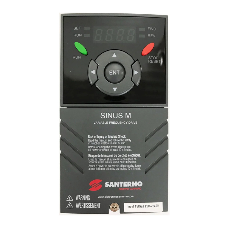
Santerno SINUS MINI Series User manual


SINUS MINI High performance Vector Control Inverter User Manual
1
Foreword
Thank you for using the SINUS MINI series of high performance vector inverter.
SINUS MINI series inverter is a new generation of high performance vector control inverter developed
by our company. The product has advanced control mode, and realizes high torque, high precision, high
reliability and wide speed drive. The inverter built-in simple PLC, PID controller, programmable input and
output terminals, RS485 interface, analog input / output control function and other rich control functions. It
provides a high degree of integration solution for equipment support, engineering transformation,
automation control and special industry application
This manual is random data ,It is only for safety considerations, installation and wiring, keyboard
operation, table function, fault code construction , maintenance and other aspects of the presentation, For
detailed functional notes, please refer to the SINUS MINI product brochure or consult our company. This
manual is the basic instruction document for your proper use and display of its superior performance and
safe operation. Please read it carefully and keep it properly, and please hand it to the end user of this
product
In the process of using,If you have any problems or special requests, please contact our company
(Office) or dealer ,You can also contact our customer service center directly, and we will be happy to serve
you,
The company has been committed to the continuous optimization of the product, because this series of
products and related information may be optimized or changed, there are possible changes, subject to
change without notice.Please forgive me for the inconvenience caused.
Reader
This instruction manual is suitable for the following personnel to read:
Inverter installation personnel, engineering and technical personnel (electrical engineers, electrical
operators, etc.), designers
Please ensure that this instruction manual reaches the end user.
General notes
Caution: Due to the dangers posed against the required operation, may lead to
moderate harm or minor injuries, and damage to the equipment;
Warning: Due to the dangers posed against the required operation, may result in
serious injury and even death;

SINUS MINI High performance Vector Control Inverter User Manual
2
Contents
CHAPTER 1 INTRODUCTION TO SINUS MINI SERIES INVERTER.................4
1.1 PRODUCT MODEL DESCRIPTION............................................................................4
1.2 SAFETY PRECAUTIONS...........................................................................................5
1.3 PRODUCT SERIES ..................................................................................................7
1.4 PRODUCT STANDARD SPECIFICATION ....................................................................9
1.5 USE NOTE.............................................................................................................10
CHAPTER 2 INVERTER INSTALLATION............................................................12
2.1 INSTALLATION ENVIRONMENT...............................................................................12
2.2 MECHANICAL INSTALLATION .................................................................................13
2.3 INVERTER SHAPE AND INSTALLATION DIMENSIONS ..............................................14
2.4 THE SHAPEAND MOUNTING DIMENSIONS OF THE OPERATING PANEL(UNIT:MM)
....................................................................................................................................15
2.5 KEYBOARD TRAY ..................................................................................................15
2.6 TERMINAL WIRING ................................................................................................16
2.7 CONTROL CIRCUIT TERMINAL FUNCTION..............................................................17
2.8 PERIPHERAL DEVICE SELECTION OF CONTROL CIRCUIT......................................18
2.9 FUNCTION OF MAIN CIRCUIT TERMINAL................................................................18
CHAPTER 3 KEYBOARD OPERATION ..............................................................19
3.1 KEYBOARD INTRODUCE........................................................................................19
3.2 DESCRIPTIONS OF INDICATORS ...........................................................................19
3.3 BUTTON DESCRIPTION OF KEYBOARD.................................................................20
3.4 KEYPAD OPERATING STATUS...............................................................................20
3.5 PANEL OPERATION METHOD................................................................................21
3.6 PARAMETER DISPLAY ...........................................................................................22
3.7 MOTOR AUTO-TUNING PROCEDURE.....................................................................23
3.8 RUNNING FOR THE FIRST TIME............................................................................24

SINUS MINI High performance Vector Control Inverter User Manual
3
CHAPTER 4 LIST OF PARAMETERS .................................................................25
4.1 FUNCTION PARAMETER TABLE.............................................................................25
CHAPTER 5 FAULT DIAGNOSIS AND TROUBLESHOOTING ........................45
5.1 FAULT QUERYAT FAULT ........................................................................................45
5.2 LIST OF FAULT AND ALARM INFORMATION............................................................46
5.3 TROUBLESHOOTING PROCEDURES .....................................................................50
CHAPTER 6 ROUTINE REPAIR AND MAINTENANCE.....................................51
6.1 ROUTINE MAINTENANCE......................................................................................51
WARRANTY AGREEMENT...................................................................................53

SINUS MINI High performance Vector Control Inverter User Manual
4
Chapter 1 Introduction to SINUS MINI Series Inverter
1.1 Product Model Description
Before unpacking the product, please check product packaging for shipping damage caused by
careless transportation and whether the specifications and type of the product complies with the order.
If any questions, please contact the supplier of SINUS MINI series inverter, or directly contact the .
Model specification:
SINUS MINI 0001 2S
Inverter Series
Code
Inverter Type
2S
Single phase 220V
Code
Motor
2
Three-phase 220V
0001
0.4KW
4T
Three-phase 380V
Fig. 1-1 Inverter symbol description
Below the right plate of the inverter case, a nameplate indicating the type and the rated value of the
inverter is attached,The contents are as follows:
第
一
章

SINUS MINI High performance Vector Control Inverter User Manual
5
1.2 safety Precautions
Description of safety marks:
Danger: The misuse may cause fire, severe injury, even death.
Note: The misuse may cause medium or minor injury and equipment damage.
Procedure qualification
This product must be operated by trained professionals. Moreover, operations personnel must undergo
professional training, familiar with equipment installation, wiring, operation and maintenance, and the correct
response to the use of various emergency situations arise.
Safety guidance
A warning sign is put forward for your safety, is to prevent the operation of injuries, and take the product and
related system damage measures; please read this manual carefully before use, and in strict accordance
with the safety rules in this manual and warning signs for the operation.
●Proper transport, storage, installation, and careful operation and maintenance is very important for the safe
operation of the inverter. During the transportation and storage to ensure the inverter from shock and
vibration, but also must ensure that the store in a dry, non corrosive gas, no conductive dust and
environmental temperature less than 60 degrees Celsius.
●This product with the dangerous voltage, and it is under the control of the movement mechanism with
potential risk, if you do not comply with the provisions of this manual or not according to the operation
requirements, may cause casualties, damage to the products and related systems.
●Do not make the connection work in power on state, otherwise the risk of death caused by electric shock; in
wiring, inspection, maintenance and operation, disconnect all power related equipment, and confirm the
main circuit of the DC voltage has dropped to a safe level, wait 5 minutes and then carry on the related work.
●The power line, the motor line and the control line must be fastened and connected. The grounding
terminal must be reliably grounded and the grounding resistance is less than 10 Omega
●The static electricity of the human body will seriously damage the internal sensitive devices, and please
comply with the measures and methods stipulated in the electrostatic prevention measures (ESD) before the
relevant operations, otherwise the frequency inverter may be damaged
●Since the output voltage of the inverter is a pulse waveform, if the output side is equipped with capacitors to
improve the power factor or lightning protection varistors, etc., be sure to remove or modify the input side of
the inverter.
SINUS MINI High performance Vector Control Inverter User Manual
6
●The output side of the inverter shall not switch devices such as circuit breakers and contactor (if the
switching device must be switched on the output side, the output current of the inverter must be zero when
the switch is switched on control)
●No matter where the fault occurs in the control equipment, it is possible to cause a shutdown and major
accidents. Therefore, please take the necessary external protection measures or backup devices
●This product can only be used in accordance with the use of the manufacturer. Without permission, it shall
not be used in special areas such as emergency response, rescue, ship, medical, aviation, nuclear facilities,
etc.
●Only the maintenance of products by the company or the company's licensing professionals, unauthorized
modification, the use of non recognition of the company's accessories, may lead to product failure. In the
maintenance, any detective devices must be promptly replaced.

SINUS MINI High performance Vector Control Inverter User Manual
7
1.3 Product Series
SINUS MINI−2S Single phase AC220V constant torque / heavy load application
Power(kW)
0.4
0.75
1.5
2.2
Motor
power(kW)
0.4
0.75
1.5
2.2/3.0
Output
Voltage(V)
Three-phase 0 to rated input voltage
Rated current(A)
2.6
4.5
7.5
12
Overload
capacity
150% 1 minute,180% 2 seconds,200% 0.5 seconds,10 minutes ( inverse
time lag feature)
Input
Rated voltage /
frequency
Single phase 200V~240V;50Hz/60Hz
Allowable voltage
range
180V~260V;Voltage imbalance:≤3% ;Allowable frequency fluctuation:±5%
Rated current(A)
5.9
8.3
14.1
24.2
Brake unit
Built-in as standard
Protection class
IP30
Cooling mode
Self-cooling
Forced air convection cooling
SINUS MINI−2T Three phase AC 220V constant torque / heavy load application
Power(kW)
0.4
0.75
1.5
2.2
4.0
/
/
/
/
/
/
/
/
/
/
Motor
power(kW)
0.4
0.75
1.5
2.2
4.0
/
/
/
/
/
/
/
/
/
/
Out
put
Voltage
(V)
Three-phase 0 to rated input voltage
Rated
current
(A)
2.6
4.5
7.5
10
17
/
/
/
/
/
/
/
/
/
/
Overload
capacity
150% 1 minute,180% 2 seconds,200% 0.5 seconds,10 minutes (inverse time lag feature)
Input
Rated
voltage /
frequency
3 phase 220V±15%;50Hz/60Hz
Allowable
voltage
range
220V±15%;Voltage imbalance:≤3% ;Allowable frequency fluctuation:±5%
Rated
current
(A)
4.1
5.3
8.0
11.8
18.1
/
/
/
/
/
/
/
/
/
/
Brake unit
Built-in as standard
External braking unit needed
Protection class
IP30
Cooling mode
Self-
cooling
Forced air convection cooling

SINUS MINI High performance Vector Control Inverter User Manual
8
SINUS MINI−4T Three phase AC 380V constant torque / heavy load application
Power(kW)
0.75
1.5
2.2
4.0
5.5
/
/
/
/
/
/
/
/
/
/
Motor
power(kW)
0.75
1.5
2.2
4.0
5.5
/
/
/
/
/
/
/
/
/
/
Out
put
Voltage
(V)
Three-phase 0 to rated input voltage
Rated
current
(A)
2.5
3.7
5.5
9
13
/
/
/
/
/
/
/
/
/
/
Overload
capacity
150% 1 minute,180% 2 seconds,200% 0.5 seconds,10 minutes (inverse time lag feature)
Inp
ut
Rated
voltage /
frequency
3 phase 380V±15%;50Hz/60Hz
Allowable
voltage
range
380V±15%;Voltage imbalance:≤3% ;Allowable frequency fluctuation:±5%
Rated
current
(A)
4.3
5.2
6.0
10.5
15.5
/
/
/
/
/
/
/
/
/
/
Brake unit
Built-in as standard
External braking unit needed
Protection class
IP30
Cooling mode
Self-
cooling
Forced air convection cooling
SINUS MINI−5T Three phase AC 460V constant torque / heavy load application
Power(kW)
0.75
1.5
2.2
4.0
5.5
/
/
/
/
/
/
/
/
/
/
Motor
power(kW)
0.75
1.5
2.2
4.0
5.5
/
/
/
/
/
/
/
/
/
/
Out
put
Voltage
(V)
Three-phase 0 to rated input voltage
Rated
current(A)
2.5
3.7
5.5
9
13
/
/
/
/
/
/
/
/
/
/
Overload
capacity
150% 1 minute,180% 2 seconds,200% 0.5 seconds,10 minutes (inverse time lag feature)
Input
Rated
voltage /
frequency
3 phase 460V±15%;50Hz/60Hz
Allowable
voltage
range
460V±15%;Voltage imbalance:≤3% ;Allowable frequency fluctuation:±5%
Rated
current(A)
4.1
4.9
5.7
9.4
12.5
/
/
/
/
/
/
/
/
/
/
Brake unit
Built-in as standard
External braking unit needed
Protection class
IP30
Cooling mode
Self-
cooling
Forced air convection cooling

SINUS MINI High performance Vector Control Inverter User Manual
9
1.4 Product standard specification
Item
Specifications
power
Voltage frequency
Single-phase 220V50/60Hz, Three-phase 380V 50/60Hz
Allowable fluctuation
voltage:±15%,frequency:±5%
Control
perfor
mance
Frequency range
0-600Hz
Output frequency
precision
The maximum frequency value ±0.1%
Output frequency
resolution
Operate keyboard up and down keys:0.01Hz Potentiometer analog input:0.2Hz
Run command given
mode
The keyboard is given; the external terminal is given; the serial port is given by the
host computer
carrier frequency
2.0-12.0KHz
Torque boost
0~20.0% adjustable, optional v/f curve optional
overload capacity
150% rated output current 1 minute,180% rated output current 2 second
Acc/Dec time
0.1~3600 second
Rated output voltage
Using the power supply voltage compensation function, the motor rated voltage is
100%, which can be set in the range of 50-100% (the output can not exceed the
input voltage)
AVR function
When the network voltage fluctuates, the output voltage fluctuation is very small and
almost constant V/F
standard feature
PID control, acceleration and deceleration time is adjustable, variable deceleration
mode, carrier frequency, torque, current limiting, power off, restart, jump frequency
control, lower frequency running, multi-speed, swing frequency, RS485, analog
output, fault slip compensation, automatic reset
braking
Energy consumption braking, DC braking
Frequency setting input
Keyboard digital setting, external terminal AI1 (0-10V/0-20mA switchable), AI2
(0-10V/0-20mA switchable), RS485 and signal combination and terminal selection
Signal feedback input
External terminal AI1 (0-10V/0-20mA switchable), AI2 (0-10V/0-20mA switchable),
RS485
Input instruction signal
Start, stop, reverse, inching, multi-speed, free parking, reset, acceleration and
deceleration time selection, frequency setting, channel selection, external fault
alarm, etc.
External output signal
Relay output, collector output, 0-10V output, 4-20mA output
protective function
Over voltage, under voltage, over current, current limit, overload, overheating,
electronic thermal overload relay, stall, data protection, etc.

SINUS MINI High performance Vector Control Inverter User Manual
10
display
Four digit display (LED)
15 kinds of parameters, such as frequency setting, output frequency, output voltage,
output current, motor speed, output torque, digital value terminals, program menu
parameters and 33kinds of fault codes
indicator lamp (LED)
Run/stop status, etc.
Operat
ing
enviro
nment
Environment
Inside, low than 1000m, free from dust, corrosive gas and direct sunlight
Ambient temperature
-10℃~+40℃(bare machine -10℃~+50℃),20%~90%RH(no condensing)
Vibration
less than 0.5g
Storage temperature
-25℃~+65℃
Installation
Wall mounted or surface mounted inside a cabinet
Protection class
IP30
Cooling
Forced air cooling.
1.5 Use note
The design of the inverter allows it to operate in an industrial environment with electromagnetic interference.
Usually, if the quality is good, it can ensure the safety of inverter and trouble free operation, please install to
ensure the inverter can run reliably and effectively avoid the electromagnetic interference caused by the
following rules.
●Ensure that the grounding cable of all control devices are connected to the inverter as transducer with
short and thick, reliably connected to public places or public star connection grounding bus motor; please
contact the nearest ground, please do not put the shell of the motor is connected to the earthing terminal or
inverter control system protection.
●When the equipment is not grounded, the contact leakage occurs. Please connect the grounding end
of the inverter to the equipment shell and motor shell, and the single phase 220V inverter N terminal must be
connected to zero line
●Conductors are preferably flat and multi-core because they are less impedance at high frequencies
●The ends of the truncated cables should be as neat as possible to ensure that the segments are as
short as possible
●Control cable wiring should be far away from the power supply cables and the motor cable, use wire
slot alone, and must be in power cables and the motor cable when crossing each other should adopt 90
degrees vertical cross.
●The cabinet is installed to ensure the contactor with a surge suppressor. Or, there is a 'R-C' damping
circuit is connected to the coil ofAC contactor, the use of varistor and corresponding coil voltage; the coil DC
contactor is connected with a "freewheeling diode" or coil device voltage corresponding to the type of

SINUS MINI High performance Vector Control Inverter User Manual
11
varistor; the output control relay in inverter contactor contactor occasions and frequent action, this is
especially important.
●The connection wire of the motor shall be shielded cable or armored cable, and the grounding end of
the shielding layer can be reliably grounded by the cable grounding card
●Install "input noise filter" can reduce the electromagnetic interference brought from the grid side of
other equipment, the input side noise filter "must be as close as possible to the inverter power input terminal,
at the same time, with the same inverter filter must be reliable grounding.
●Install "the output side filter can reduce noise" wireless interference from the motor and the inductive
interference, "the output side filter noise" must be as close as possible to the inverter output terminals, at the
same time, with the same inverter filter must be reliable grounding.
●Shielded cable or twisted pair shall be used whenever the control loop is connected
●Adding the "zero phase reactor" in the power line near the inverter input terminal, adding the "zero
phase reactor" in the motor line near the inverter output terminals, adding "zero phase reactor" in the control
line near the inverter control terminal, can effectively reduce the electromagnetic interference and the main
power cable connected inverter induction.
●Grounding, correct and reliable grounding are the basic conditions for the safe and reliable operation
of this product. In order to properly connect the inverter to the ground, please read the following cautions
carefully
warning
●To avoid electric shock, please use the dimensions specified in the electrical
equipment technical standard, and shorten the wiring length as much as possible, and
the grounding resistance is below 10 Omega.Otherwise, the leakage current caused by
the inverter will lead to the unstable potential of the grounding terminal far from the
grounding point, which will lead to an electric shock accident
Causion
●Do not share the ground wire with the welder or power equipment that requires high
current / pulse current, otherwise it will cause abnormal operation of the inverter
●When using multiple inverters, do not loop the ground. Otherwise, the inverter will act
abnormally
●The motor must be grounded independently, and the motor casing can not be
connected to the ground terminal of the inverter, nor can the same ground network be
shared with the control system

SINUS MINI High performance Vector Control Inverter User Manual
12
Chapter 2 Inverter Installation
To ensure the safe use of this product, to maximize the performance of the inverter and to ensure the
reliable operation of the inverter, please strictly follow the environment, wiring, ventilation and other
requirements described in this chapter
2.1 Installation environment
In order to give full play to the performance of this product and maintain its function for a long time, the
installation environment is very important. Please install this product in the environment that meets the
requirements shown in the following table
Environment
Requirement
Installation
environment
Installation indoor without direct sunlight
Work temperature
-10 ~+40℃
Storage
Temperature
-20 ~+60℃
Environment
temperature
No condensation under 95%RH
Ambient
environment
Please install the inverter in the following places:
●No oil fog, corrosive gas, flammable gas, dust and other places;
●Metal powder, oil, water and other foreign matter will not enter the frequency
inverter inside the place (do not install the frequency inverter on wood and other
flammable substances above);
●A place where radioactive substances are not flammable;
●A place where no noxious gas or liquid is found;
●A place where little salt is eaten;
●A place where there is no direct sunlight
Height above sea
level
Below 1000m
Vibration
Below 10~20Hz: 9.8m/s2; Below 20~55Hz∶5.9m/s2

SINUS MINI High performance Vector Control Inverter User Manual
13
Installation and
cooling
●The inverter shall not be installed horizontally or horizontally, and vertical and
vertical installation must be guaranteed;
●High resistance heating equipment such as braking resistance, please install
independently, avoid and inverter installed in the same cabinet, it is strictly prohibited
to brake resistance and other high heating equipment installed in the inverter inlet
2.2 Mechanical installation
●SINUS MINI series inverter components
●Installation space, direction and space
Installation: single frequency governor to install in indoor ventilated place, and a wall hanging cabinet type or
vertical installation. And with the adjacent items or baffle (wall) must keep enough space.
installation diagram of single inverter

SINUS MINI High performance Vector Control Inverter User Manual
14
Multiple installation: when installing multiple inverters in the control cabinet, please ensure the following
installation space.
Installation diagram of multi inverters
2.3 Inverter shape and installation dimensions
Voltage
level
Inverter model
Outline construction and installation dimension(mm)
Weight
(kg)
W
H
D
W1
H1
Mounting hole d
Single
phase
220V
SINUS−0001 2S
78
188
126
55
178
4
1.5
SINUS−0002 2S
SINUS−0003 2S
SINUS−0004 2S
96
225
137
65
215
4
2
Three
-phase
220V
SINUS−0001 2T
78
188
126
55
178
4
1.5
SINUS−0002 2T
SINUS−0003 2T
SINUS−0004 2T
96
225
137
65
215
4
2

SINUS MINI High performance Vector Control Inverter User Manual
15
Three
-phase
380V
SINUS−0002 4T
78
188
126
55
178
4
1.5
SINUS−0003 4T
SINUS−0004 4T
SINUS−0005 4T
96
225
137
65
215
4
2
SINUS−0006 4T
Three
-phase
460V
SINUS−0002 5T
78
188
126
55
178
4
1.5
SINUS−0003 5T
SINUS−0004 5T
SINUS−0005 5T
96
225
137
65
215
4
2
SINUS−0006 5T
2.4 The shape and mounting dimensions of the operating panel(unit:mm)
Keyboard (SINUS MINI-DF01) Rear view of Keyboard
2.5 Keyboard tray
SINUS MINI−DF03 is the operation panel to install plate cabinet use, its shape and size are as follows:

SINUS MINI High performance Vector Control Inverter User Manual
16
2.6 Terminal wiring
This section describes all the precautions and requirements that ensure the user's safe use of the
product, maximize the performance of the inverter, and ensure the reliable operation of the inverter.The
standard wiring diagram is as follows:
B
R
S
T
U
V
W
DI1
DI2
DI3
DI4
DI5/HD1
+10V
AI1
GND
10kΩ P
AO1
GND
RC1
+24V
Y1
P
RA1
RB1
250V AC/1A
30V DC/1A
CM
P
R
S
T
+10V
AI2
GND
10kΩ P
+24V
OP
CM
+24V
485+
485-
GND
OP
CM
3
2
1
J7
3
2
1
J7
Drain
drive(default)
source drive
3
2
1
J4 2-3short-circuit
AI1C 0-20mA DC
1-2 short-circuit(default)
AI1V 0-10V DC
3
2
1
J5 2-3short-circuit
AI1C 0-20mA DC
1-2
short-circuit(default)
AI1C 0-20mA DC
3
2
1
2-3short-circuit
AO1C 0-2mA DC
1-2 short-circuit(default)
AO1V 0-10V DC
3
2
1
J6
485
terminal
resistor
selecting
switch
Circuit breaker
Three phase AC
power supply
Power grounding
Motor
motor grounding
Multi function input 1
Multi function input 2
Multi function input 3
Multi function input 4
Multi function input 5
Braking Resistor
Main circult
Control circult
Analog output 1
Relay output1
Relay
Modbus
communication
RS485
Shielding
cable
Twisted shielding
cable
optional
J3
P
Note:
Analog output is frequency, current, voltmeter and other instructions for specific output, can not be used for
feedback and other control operations

SINUS MINI High performance Vector Control Inverter User Manual
17
2.7 Control circuit terminal function
2.7.1 Control loop terminal line
GND AI1 AI2 DI1 DI3 DI5 +24V COM
+10V AO1 485+485- COM
RA1 RB1 RC1
Y1
DI4
DI2
2.7.2 Control circuit terminal instruction
Type
Terminal
sign
T
erminal
Name
Function Description
Power
supply
+10V-GND
External terminal of
10V power supply
Provide +10V power supply for external units, with maximum
output current of 10mA.
It is generally used as the operating power supply for the
external potentiometer.
The potentiometer resistance range is 1kΩ to 5kΩ.
+24V-COM
External terminal of
24V power supply
Provide +24V power supply for external units. It is generally
used as the operating power supply for digital input/output
terminal and the external sensor.
Maximum output current:200mA
OP
External power input
terminals
When using external signal to drive DI1~DI5,OP should be
connected to external power supply,The factory defaults (J7)
to the 24V connection
Analog
input
AI1-GND
Analog input
terminal 1
1. Input voltage range:DC 0V ~ 10V /4mA ~ 20mA, chosen
by jumper J4 on control board.
2. Input impedance:22kΩ of voltage input, 500Ω of current
input.
AI2-GND
Analog input
terminal 2
1.Input range:DC 0V~10V/4mA~20mA,chosen by jumper
J5 on control board
2.Input impedance:22kΩ of voltage input, 500Ω of current
input.
Digital
Input
DI1-OP
Digital Input 1
1. Optical coupling isolation,bipolar input.
2. Input impedance:4.7kΩ.
3. Electrical level input range:9V~30V.
DI2-OP
Digital Input 2
DI3-OP
Digital Input 3
DI4-OP
Digital Input 4
DI5-OP
Digital Input 5
Input impedance:2.4 kΩ.
HDI
DI5-OP
High-speed pulse
input terminal
(Optional)
DI5 can be used as high-speed pulse input channel.
Maximum input frequency:100kHz.
Analog
output
AO1-GND
Analog output 1
The voltage or current output is determined by jumper J3 on
the control panel.
Output voltage range:0V to 10V Output current range:0mA
to 20mA.

SINUS MINI High performance Vector Control Inverter User Manual
18
Digital
Output
Y1-COM
Digital output 1
(High-speed pulse
output)
(Optional)
Optical coupling isolation,dual polarity open collector output.
Output voltage range:0V to 24V Output current range:0mA
to 50mA
Relay
output1
RB1-RA1
Normally closed
Contact driving capacity:AC250V,3A,COSø=0.4
RB1-RC1
Normally open
terminal
485
485+
485Positive signal of
differential signal
Rate:1200/2400/4800/9600/19200/38400
Up to 32 units at most, more than 32 units, use
repeaters.The longest distance 500m (shielded twisted pair
cable using standard) J6:485Terminal resistance selection:
ON is a 100 Omega terminal resistor,OFF is no terminal
resistance
485−
485Negative side of
differential signal
GND
485Shielding GND
of communication
Internal isolation from COM
NOTE:
﹡If the user adjustable potentiometer in + 10V and GND, potentiometer resistance should not be less
than 5K Omega
2.8 Peripheral device selection of control circuit
Terminal number
Terminal
screw
tightening
torque(N·m)
AWG
mm2
Types of wires
+10V、AO1、485+、485−、DI2、DI4、
Y1、COM
M3
0.5~0.6
0.75
Double glue
shielded cable
GND、AI1、AI2、DI1、DI3、DI5、+24V、
COM
M3
0.5~0.6
0.75
shielded cable
2.9 Function of main circuit terminal
E P B R S T U V W E P BL1
L2 U V W
OUTPUT
INPUT
BRAKE BRAKE INPUT OUTPUT
SINUS MINI−00xx 4T SINUS−00xx 2S
Terminal symbol
Terminal name and function description
R、S、T(L1、L2)
Three (single) phase current input terminals
P 、B
Braking resistor connecting terminal
U、V、W
Three phase AC output terminal
E
Ground terminal PE

SINUS MINI High performance Vector Control Inverter User Manual
19
Chapter 3 Keyboard Operation
3.1 Keyboard introduce
Figure 3 - 1 Keyboard(SINUS MINI−DF01)
3.2 Descriptions of Indicators
Indicator sign
name
Meanings
Indicator sign
name
Meanings
Color
LOCAL/REMO
T
Running command
reference mode
indicator
OFF Running command is given by keyboard
ON: Running command is given by terminal
operation
Flashing:Running command is given by host
computer
red
RUN
Running status
indicator
ON: running state
OFF: stop state
Flashing: stopping state
green
FWD/REV
Positive and negative
indicator light
ON: forward running
OFF :reverse running
red
TUNE/TC
Tuning/Fault indicator
ON: Fault condition
OFF: Normal condition
red
Hz
Frequency indicator
ON Current display parameter is running frequency
red
A
Current indicator
ON: Current display parameter is current
red
V
Voltage indicator
ON: Current display parameter is voltage
red
RPM(Hz+A)
Rotating speed
indicator
ON: Current display parameter is rotating speed
red
S/M(A+V)
Time indicator
ON: Current display parameter is time
red
%(Hz+V)
% indicator
ON :Current display parameter is percentage
red
This manual suits for next models
18
Table of contents
Other Santerno Inverter manuals

Santerno
Santerno Sinus M User manual

Santerno
Santerno SUNWAY SI User manual

Santerno
Santerno SUNWAY TG610 1000V TE OD User manual

Santerno
Santerno SINUS VEGA 2S User manual

Santerno
Santerno SUNWAY M XS User manual

Santerno
Santerno SUNWAY M XS User manual

Santerno
Santerno Sinus Penta User manual

Santerno
Santerno SUNWAY M XS User manual
Popular Inverter manuals by other brands

Toshiba
Toshiba TOSVERT VF-FS1 Series instruction manual

Volt Polska
Volt Polska Sinus Plus 1500 manual

Envertech
Envertech EVT2000 user manual

Deye
Deye SUN-3.6K-SG05LP1-EU user manual

Hitachi
Hitachi HFC-VWS3 U SERIES, HFC-VWS3 H SERIES instruction manual

Chicago Electric
Chicago Electric 66817 Set up and operating instructions