Crown Micro X-3.6KW-M User manual

USER MANUAL
X-3.6KW-M / X-5.6KW-M
Hybrid Inverter
With MPPT Solar Charger
Version: 1.0

1
Table Of Contents
ABOUT THIS MANUAL ......................................................................................................................................2
Purpose............................................................................................................................................................2
Scope...............................................................................................................................................................2
SAFETY INSTRUCTIONS...................................................................................................................................2
INTRODUCTION .................................................................................................................................................3
Features...........................................................................................................................................................3
Basic System Architecture...............................................................................................................................3
Product Overview.............................................................................................................................................4
INSTALLATION...................................................................................................................................................5
Unpacking and Inspection................................................................................................................................5
Preparation ......................................................................................................................................................5
Mounting the Unit.............................................................................................................................................5
Battery Connection ..........................................................................................................................................6
AC Input/Output Connection............................................................................................................................7
PV Connection.................................................................................................................................................9
Final Assembly...............................................................................................................................................11
Communication Options.................................................................................................................................11
OPERATION......................................................................................................................................................12
Power ON/OFF ..............................................................................................................................................12
Operation and Display Panel.........................................................................................................................12
LCD Display Icons .........................................................................................................................................13
LCD Setting....................................................................................................................................................16
Display Setting...............................................................................................................................................24
Operating Mode Description..........................................................................................................................27
Battery Equalization Description....................................................................................................................30
Fault Reference Code....................................................................................................................................32
Warning Indicator...........................................................................................................................................33
CLEARANCE AND MAINTENANCE FOR ANTI-DUST KIT............................................................................34
Overview........................................................................................................................................................34
Clearance and Maintenance..........................................................................................................................34
SPECIFICATIONS.............................................................................................................................................35
Table 1 Line Mode Specifications ...................................................................................................................35
Table 2 Inverter Mode Specifications .............................................................................................................36
Table 3 Charge Mode Specifications ..............................................................................................................37
Table 4 General Specifications .......................................................................................................................37
TROUBLE SHOOTING.....................................................................................................................................38
Appendix I: Approximate Back-up Time Table .............................................................................................39
Appendix II: The Wi-Fi Operation Guide........................................................................................................40

2
ABOUT THIS MANUAL
Purpose
This manual describes the assembly, installation, operation and troubleshooting of this unit. Please read
this manual carefully before installations and operations. Keep this manual for future reference.
Scope
This manual provides safety and installation guidelines as well as information on tools and wiring.
SAFETY INSTRUCTIONS
WARNING: This chapter contains important safety and operating instructions. Read and
keep this manual for future reference.
1. Before using the unit, read all instructions and cautionary markings on the unit, the batteries and all
appropriate sections of this manual.
2. CAUTION --To reduce risk of injury, charge only deep-cycle lead acid type rechargeable batteries.
Other types of batteries may burst, causing personal injury and damage.
3. Do not disassemble the unit. Take it to a qualified service center when service or repair is required.
Incorrect re-assembly may result in a risk of electric shock or fire.
4. To reduce risk of electric shock, disconnect all wirings before attempting any maintenance or cleaning.
Turning off the unit will not reduce this risk.
5. CAUTION –Only qualified personnel can install this device with battery.
6. NEVER charge a frozen battery.
7. For optimum operation of this inverter/charger, please follow required spec to select appropriate cable
size. It’s very important to correctly operate this inverter/charger.
8. Be very cautious when working with metal tools on or around batteries. A potential risk exists to drop
a tool to spark or short circuit batteries or other electrical parts and could cause an explosion.
9. Please strictly follow installation procedure when you want to disconnect AC or DC terminals. Please
refer to INSTALLATION section of this manual for the details.
10. One piece of 150A fuse is provided as over-current protection for the battery supply.
11. GROUNDING INSTRUCTIONS -This inverter/charger should be connected to a permanent grounded
wiring system. Be sure to comply with local requirements and regulation to install this inverter.
12. NEVER cause AC output and DC input short circuited. Do NOT connect to the mains when DC input
short circuits.
13. Warning!! Only qualified service persons are able to service this device. If errors still persist after
following troubleshooting table, please send this inverter/charger back to local dealer or service center
for maintenance.
14. WARNING: Because this inverter is non-isolated, only three types of PV modules are acceptable:
single crystalline, poly crystalline with class A-rated and CIGS modules. To avoid any malfunction, do
not connect any PV modules with possible current leakage to the inverter. For example, grounded PV
modules will cause current leakage to the inverter. When using CIGS modules, please be sure NO
grounding.
15. CAUTION: It’s requested to use PV junction box with surge protection. Otherwise, it will cause
damage on inverter when lightning occurs on PV modules.
3
INTRODUCTION
This is a multi-function inverter/charger, combining functions of inverter, solar charger and battery charger to
offer uninterruptible power support with portable size. Its comprehensive LCD display offers user-configurable
and easy-accessible button operation such as battery charging current, AC/solar charger priority, and
acceptable input voltage based on different applications.
Features
Pure sine wave inverter
Inverter running without battery
Configurable input voltage range for home appliances and personal computers via LCD setting
Configurable battery charging current based on applications via LCD setting
Configurable AC/Solar Charger priority via LCD setting
Compatible to mains voltage or generator power
Auto restart while AC is recovering
Overload/ Over temperature/ short circuit protection
Smart battery charger design for optimized battery performance
Cold start function
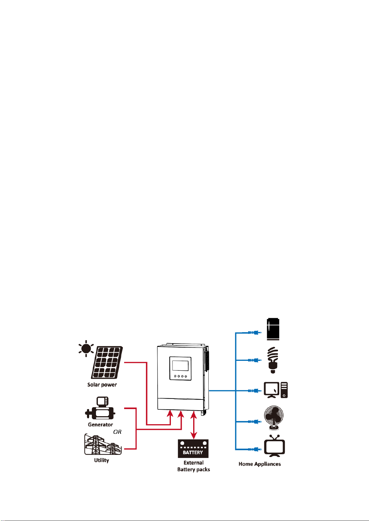
Basic System Architecture
The following illustration shows basic application for this inverter/charger. It also includes following devices to
have a complete running system:
Generator or Utility.
PV modules
Consult with your system integrator for other possible system architectures depending on your requirements.
This inverter can power all kinds of appliances in home or office environment, including motor-type appliances
such as tube light, fan, refrigerator and air conditioner.
Figure 1 Hybrid Power System
4
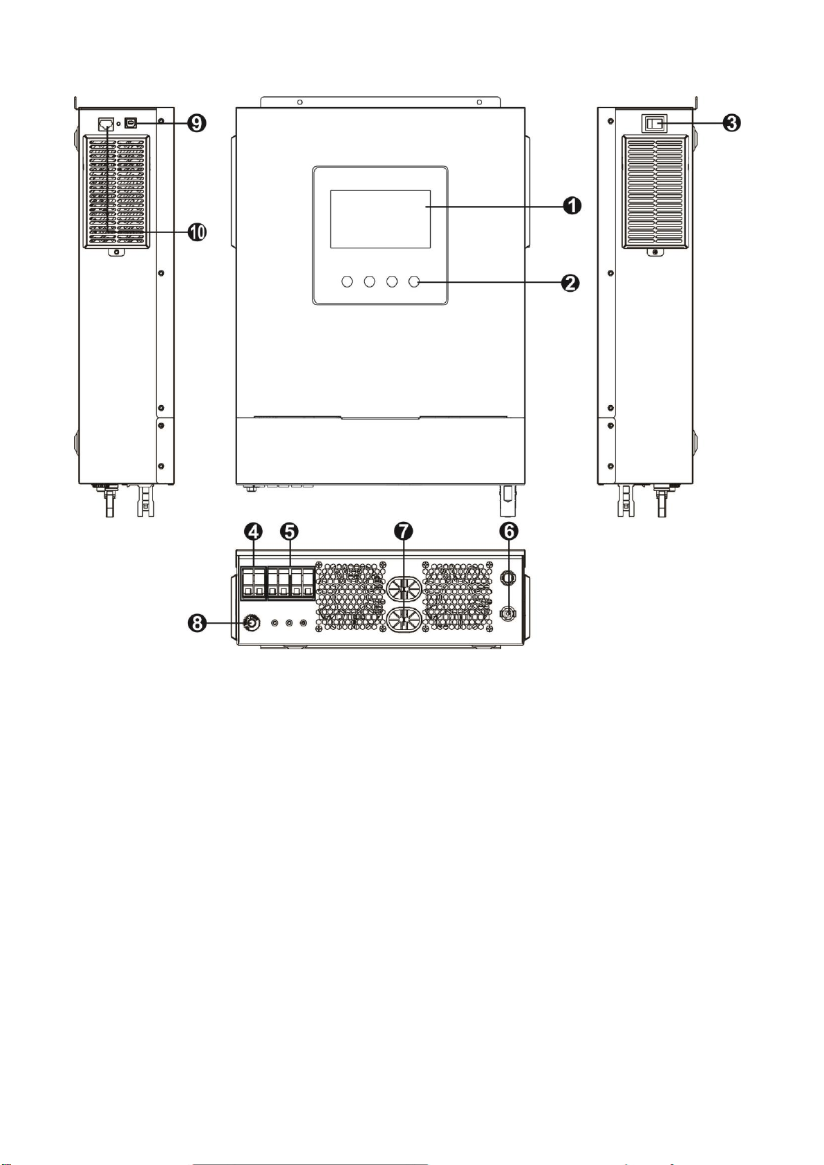
Product Overview
1. LCD display
2. Function keys
3. Power on/off switch
4. AC input
5. AC output
6. PV input
7. Battery input
8. Circuit breaker
9. USB communication port
10. RS-232 communication port
5
INSTALLATION
Unpacking and Inspection
Before installation, please inspect the unit. Be sure that nothing inside the package is damaged. You should
have received the following items inside of package:
The unit x 1
User manual x 1
Communication cable x 1
Software CD x 1
DC Fuse x 1
PV connectors x 1 set
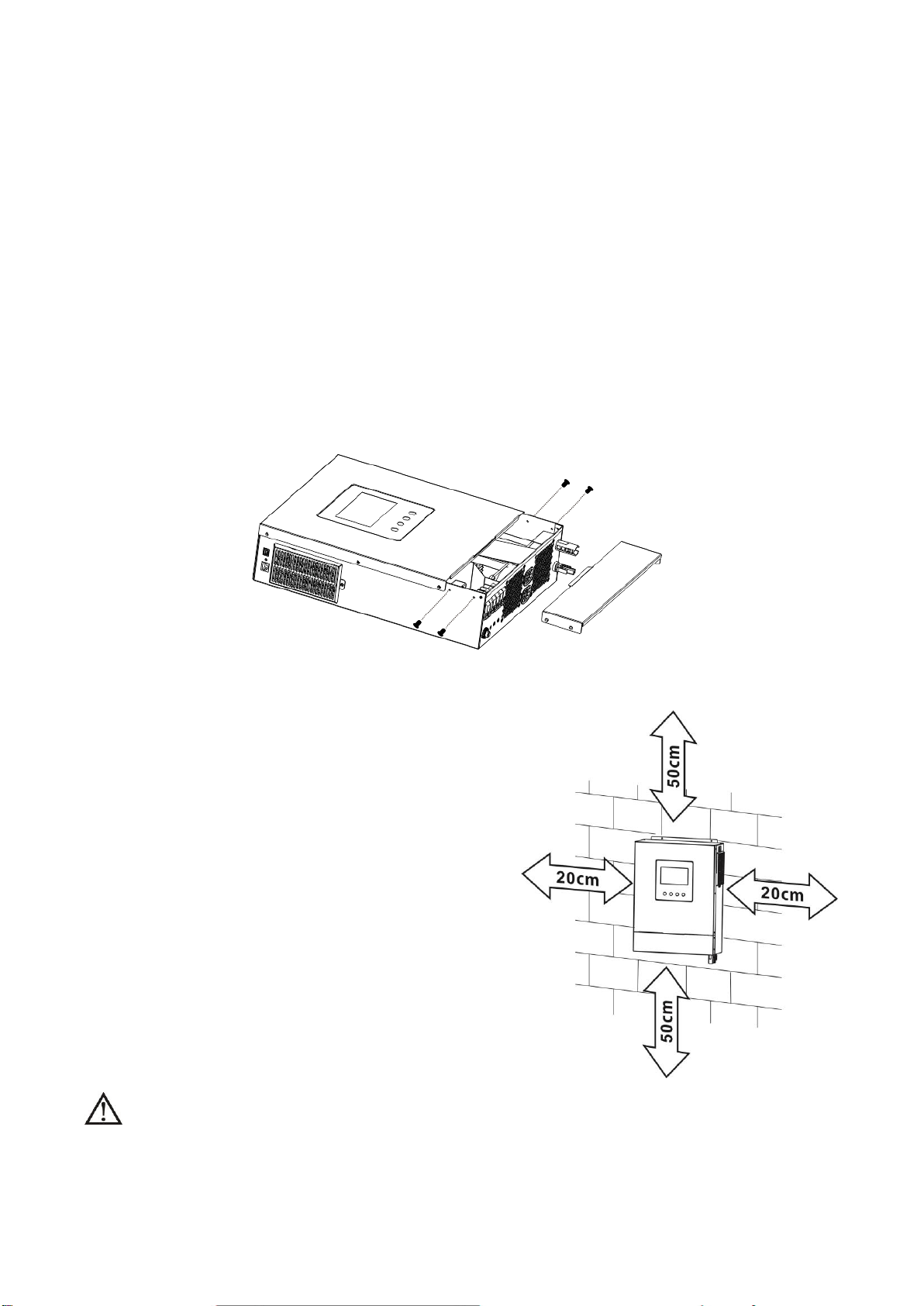
Preparation
Before connecting all wirings, please take off bottom cover by removing four screws as shown below.
Mounting the Unit
Consider the following points before selecting where to install:
Do not mount the inverter on flammable construction
materials.
Mount on a solid surface
Install this inverter at eye level in order to allow the LCD
display to be read at all times.
For proper air circulation to dissipate heat, allow a
clearance of approx. 20 cm to the side and approx. 50 cm
above and below the unit.
The ambient temperature should be between 0°C and
55°C to ensure optimal operation.
The recommended installation position is to be adhered
to the wall vertically.
Be sure to keep other objects and surfaces as shown in
the diagram to guarantee sufficient heat dissipation
and to have enough space for removing wires.
SUITABLE FOR MOUNTING ON CONCRETE OR OTHER NON-COMBUSTIBLE SURFACE ONLY.

6
Install the unit by screwing two screws. It’s recommended to use M4 or M5 screws.
Battery Connection
CAUTION: For safety operation and regulation compliance, it’s requested to install a separate DC over-current
protector or disconnection device between battery and the inverter. It may not be necessary to have a
disconnection device in some applications, however, it’s still recommended to have over-current protection
installed. Please refer to typical amperage as required.
WARNING! All wiring must be performed by a qualified personnel.
WARNING! It’s very important for system safety and efficient operation to use
appropriate cable for battery connection. To reduce risk of injury, please use the
proper recommended cable and terminal size as below.
Recommended battery cable and terminal size:
Model
Typical
Amperage
Wire Size
Cable
mm2
Ring Terminal
Torque
Value
Dimensions
D (mm)
L (mm)
X-3.6KW-M
167A
2*4AWG
25
8.4
33.2
5 Nm
X-5.6KW-M
129.6A
1*2AWG
38
8.4
39.2
2*4AWG
25
8.4
33.2
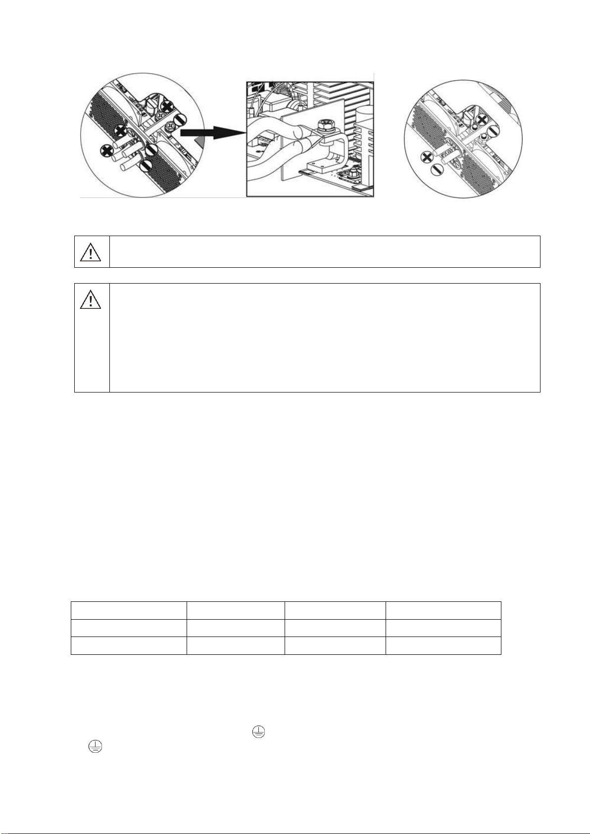
Please follow below steps to implement battery connection:
1. 3.6KW model supports 24VDC system and 5.6KW model supports 48VDC system. Connect all battery packs
as below chart. It is recommend to connect minimum of 100Ah capacity battery for 3.6KW model and
200Ah capacity battery for 5.6KW model.
2. Prepare four battery wires for 3.6KW model and two or four battery wires for 5.6KW model depending on
cable size (refer to recommended cable size table). Apply ring terminals to your battery wires and secure it
to the battery terminal block with the bolts properly tightened. Refer to battery cable size for torque value.
Ring terminal:
7
Make sure polarity at both the battery and the inverter is correctly connected and ring terminals are
secured to the battery terminals.
X-3.6KW-M/ X-5.6KW-M X-5.6KW-M
WARNING: Shock Hazard
Installation must be performed with care due to high battery voltage in series.
CAUTION!! Do not place anything between the flat part of the inverter terminal and the ring
terminal. Otherwise, overheating may occur.
CAUTION!! Do not apply anti-oxidant substance on the terminals before terminals are
connected tightly.
CAUTION!! Before making the final DC connection or closing DC breaker/disconnector, be sure
positive (+) must be connected to positive (+) and negative (-) must be connected to negative
(-).
AC Input/Output Connection
CAUTION!! Before connecting to AC input power source, please install a separate AC breaker between
inverter and AC input power source. This will ensure the inverter can be securely disconnected during
maintenance and fully protected from over current of AC input. The recommended spec of AC breaker is 32A
for 3.6KW and 50A for 5.6KW.
CAUTION!! There are two terminal blocks with “IN” and “OUT” markings. Please do NOT mis-connect input
and output connectors.
WARNING! All wiring must be performed by a qualified personnel.
WARNING! It's very important for system safety and efficient operation to use appropriate cable for AC input
connection. To reduce risk of injury, please use the proper recommended cable size as below.
Suggested cable requirement for AC wires
Model
Gauge
Cable (mm2)
Torque Value
X-3.6KW-M
12 AWG
4
1.2 Nm
X-5.6KW-M
10 AWG
6
1.2 Nm
Please follow below steps to implement AC input/output connection:
1. Before making AC input/output connection, be sure to open DC protector or disconnector first.
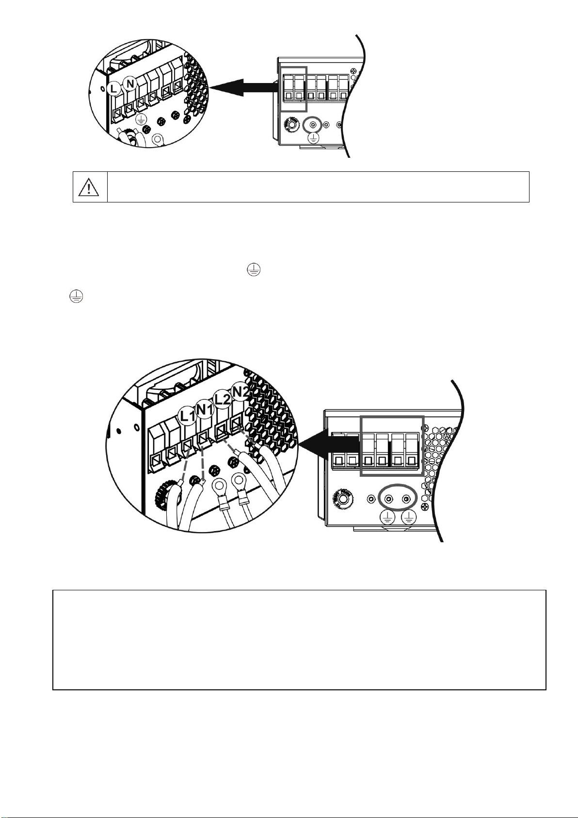
2. Remove insulation sleeve 10mm for six conductors. And shorten phase L and neutral conductor N 3 mm.
3. Insert AC input wires according to polarities indicated on terminal block and tighten the terminal screws. Be
sure to connect PE protective conductor ( ) first.
→Ground (yellow-green)
L→LINE (brown or black)
N→Neutral (blue)
8
WARNING:
Be sure that AC power source is disconnected before attempting to hardwire it to the unit.
4. This inverter is equipped with dual-output. There are four terminals (L1/N1, L2/N2) available on output port.
It’s set up through LCD program or monitoring software to turn on and off the second output. Refer to “LCD
setting” section for the details.
Insert AC output wires according to polarities indicated on terminal block and tighten terminal screws. Be
sure to connect PE protective conductor ( ) first.
→Ground (yellow-green)
L1→LINE (brown or black)
N1→Neutral (blue)
L2→LINE (brown or black)
N2→Neutral (blue)
5. Make sure the wires are securely connected.
CAUTION: Appliances such as air conditioner are required at least 2~3 minutes to restart because it’s required
to have enough time to balance refrigerant gas inside of circuits. If a power shortage occurs and recovers in a
short time, it will cause damage to your connected appliances. To prevent this kind of damage, please check
manufacturer of air conditioner if it’s equipped with time-delay function before installation. Otherwise, this
inverter/charger will trig overload fault and cut off output to protect your appliance but sometimes it still causes
internal damage to the air conditioner.
9
PV Connection
CAUTION: Before connecting to PV modules, please install separately DC circuit breakers between inverter
and PV modules.
NOTE1: Please use 600VDC/30A circuit breaker.
NOTE2: The overvoltage category of the PV input is II.
Please follow the steps below to implement PV module connection:
Step 1: Check the input voltage of PV array modules. This system is applied with two strings of PV array. Please
make sure that the maximum current load of each PV input connector is 18A.
Step 2: Disconnect the circuit breaker and switch off the DC switch.
Step 3: Assemble provided PV connectors with PV modules by the following steps.
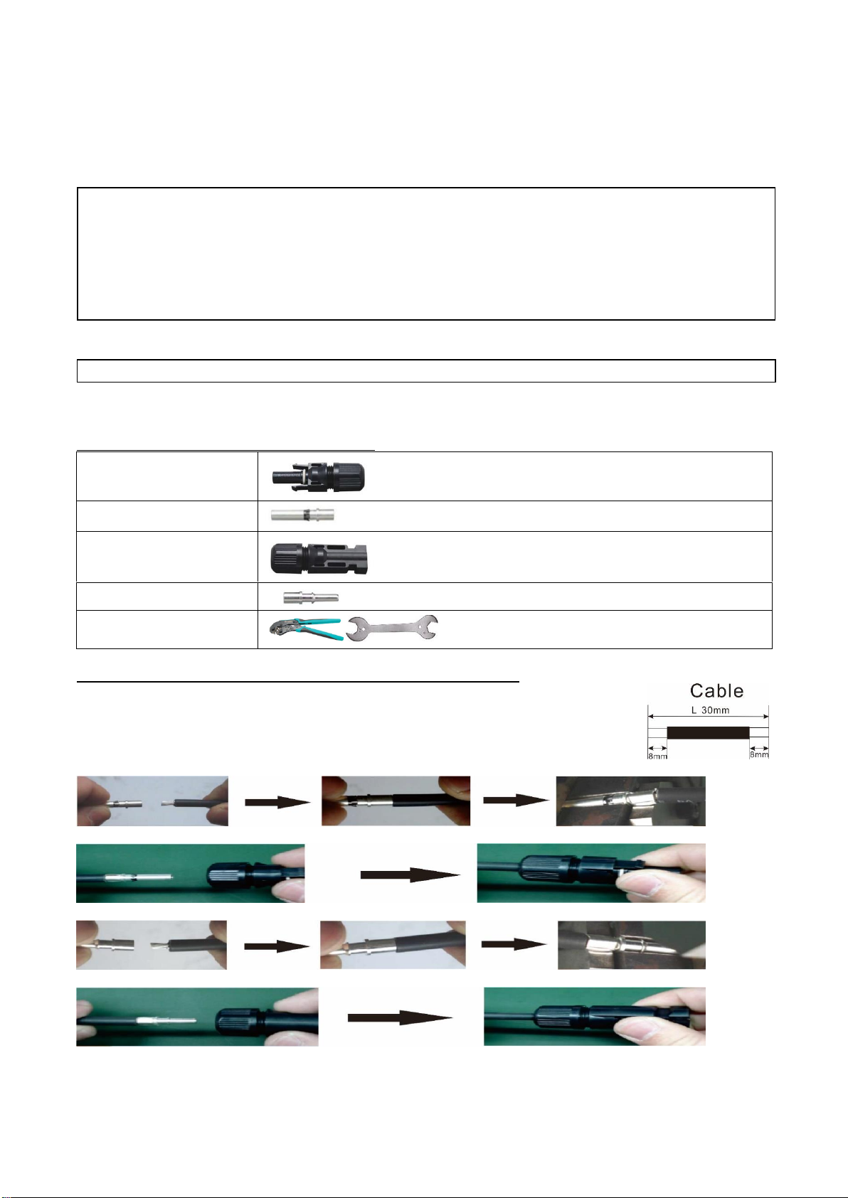
Components for PV connectors and Tools:
Female connector housing
Female terminal
Male connector housing
Male terminal
Crimping tool and spanner
Prepare the cable and follow the connector assembly process:
Insert striped cable into female terminal and crimp female terminal as shown below.
Insert assembled cable into female connector housing as shown below.
Insert striped cable into male terminal and crimp male terminal as shown below.
Insert assembled cable into male connector housing as shown below.
CAUTION: Exceeding the maximum input voltage can destroy the unit!! Check the system before wire connection.
WARNING: Because this inverter is non-isolated, only three types of PV modules are acceptable: single
crystalline and poly crystalline with class A-rated and CIGS modules.
To avoid any malfunction, do not connect any PV modules with possible current leakage to the inverter. For
example, grounded PV modules will cause current leakage to the inverter. When using CIGS modules, please
be sure NO grounding.
CAUTION: It’s required to use PV junction box with surge protection. Otherwise, it will cause damage on
inverter when lightning occurs on PV modules.
Strip one cable 8 mm on both end sides and be careful NOT to nick conductors.
10
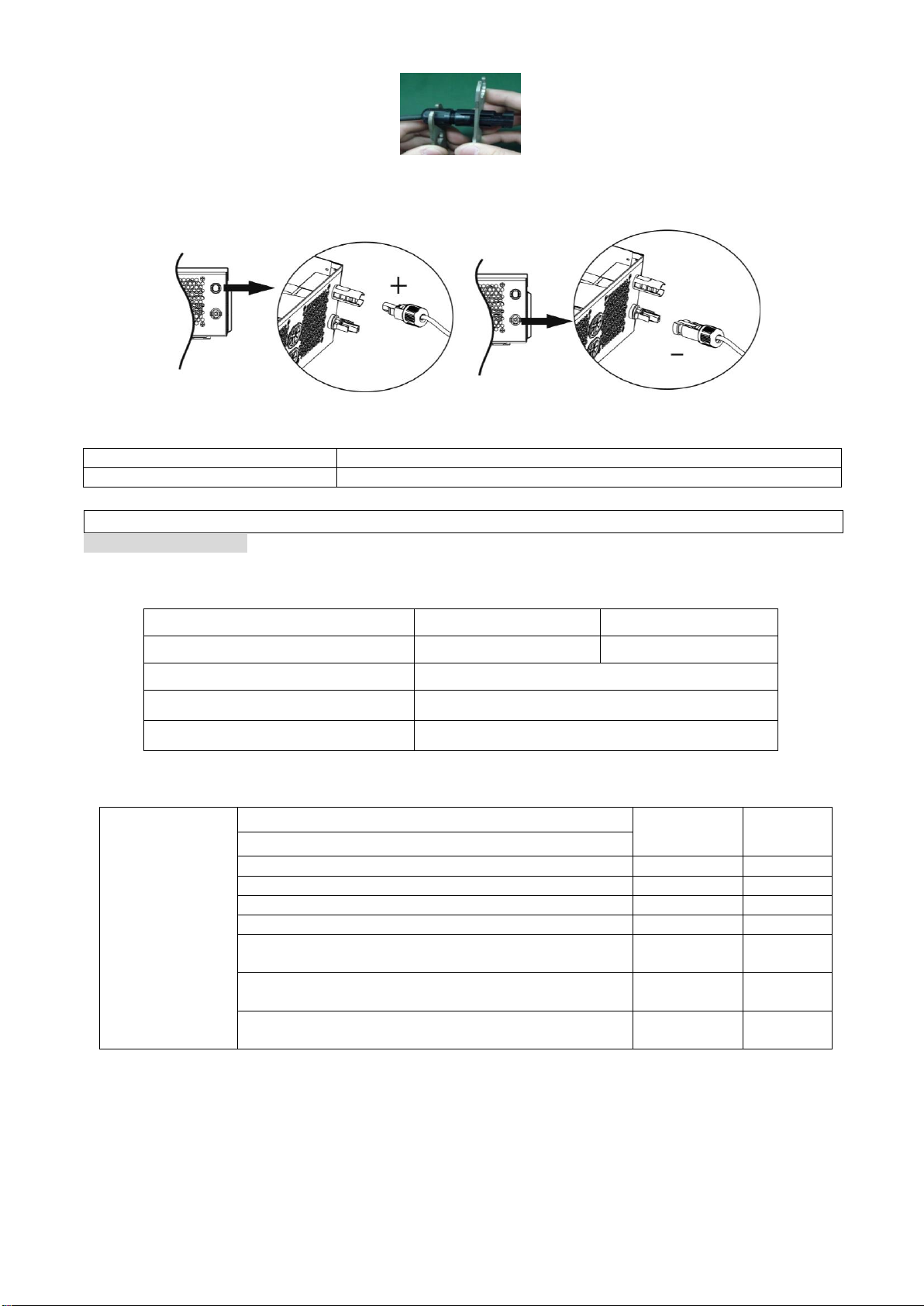
Then, use spanner to screw pressure dome tightly to female connector and male connector as shown below.
Step 4: Check correct polarity of connection cable from PV modules and PV input connectors. Then, connect
positive pole (+) of connection cable to positive pole (+) of PV input connector. Connect negative pole (-) of
connection cable to negative pole (-) of PV input connector.
WARNING! For safety and efficiency, it's very important to use appropriate cables for PV module connection.
To reduce risk of injury, please use the proper cable size as recommended below.
Conductor cross-section (mm2)
AWG no.
4~6
10~12
PV Module Selection:
When selecting proper PV modules, please be sure to consider below parameters:
1. Open circuit Voltage (Voc) of PV modules not exceeds max. PV array open circuit voltage of inverter.
2. Open circuit Voltage (Voc) of PV modules should be higher than min. Start-up Voltage.
INVERTER MODEL
X-3.6KW-M
X-5.6KW-M
Max. PV Array Power
4000W
6000W
Max. PV Array Open Circuit Voltage
500Vdc
PV Array MPPT Voltage Range
120Vdc~450Vdc
Start-up Voltage
150Vdc +/- 10Vdc
Take 250Wp PV module as an example. After considering above two parameters, the recommended module
configurations are listed as below table.
Solar Panel Spec.
(reference)
- 250Wp
- Vmp: 30.1Vdc
- Imp: 8.3A
- Voc: 37.7Vdc
- Isc: 8.4A
- Cells: 60
SOLAR INPUT
Q'ty of panels
Total input
power
Min in series: 6 pcs, max. in series: 12 pcs.
6 pcs in series
6 pcs
1500W
8 pcs in series
8 pcs
2000W
12 pcs in series
12 pcs
3000W
8 pieces in series and 2 sets in parallel
16 pcs
4000W
10 pieces in series and 2 sets in parallel (only for 5.6KVA
model)
20 pcs
5000W
11 pieces in series and 2 sets in parallel
(only for 5.6KVA model)
22 pcs
5500W
12 pieces in series and 2 sets in parallel
(only for 5.6KVA model)
24 pcs
6000W
CAUTION: Never directly touch the terminals of inverter. It might cause lethal electric shock.
11
Take the 555Wp PV module as an example. After considering above two parameters, the recommended
module configurations are listed in the table below.
Solar Panel Spec.
(reference)
- 555Wp
- Imp: 17.32A
- Voc: 38.46Vdc
- Isc: 18.33A
- Cells: 110
SOLAR INPUT
Q'ty of panels
Total input
power
Min in series: 2 pcs, max. in series: 11 pcs.
2pcs in series
2 pcs
1110W
4pcs in series
4 pcs
2220W
6 pcs in series
6 pcs
3330W
7 pcs in series
7 pcs
3885W
8 pcs in series (only for X-5.6KW-M model)
8 pcs
4440W
10 pcs in series (only for X-5.6KW-M model)
10 pcs
5550W
11 pcs in series (only for X-5.6KW-M model)
11 pcs
6000W
Final Assembly
After connecting all wirings, please put bottom cover back by screwing two screws as shown below.
Communication Options
Serial Connection
Please use the supplied serial cable to connect between the inverter and your PC. Install the monitoring
software from the bundled CD and follow the on-screen instructions to complete your installation. For
detailed software operation, refer to the software user manual on the bundled CD.
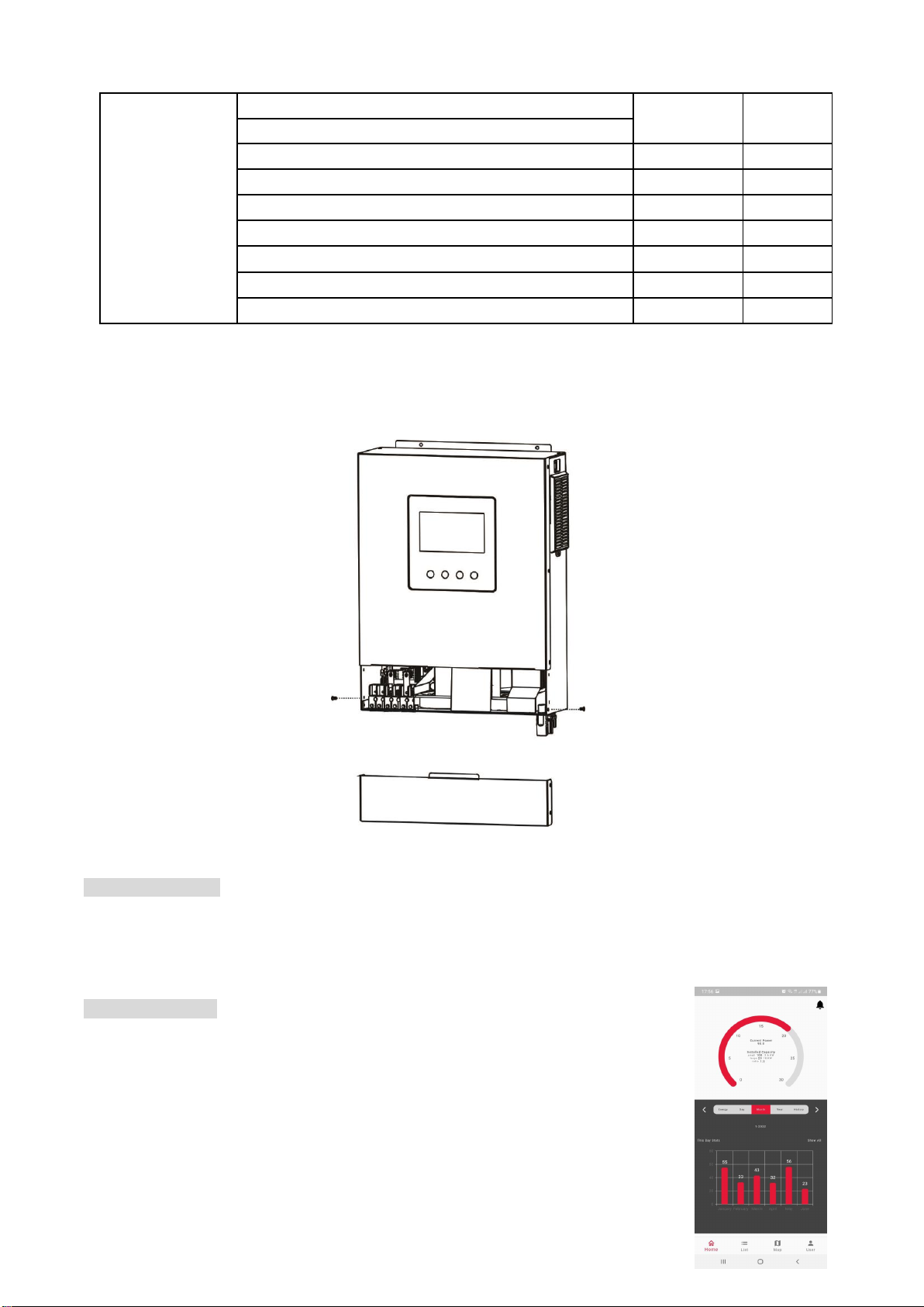
Wi-Fi Connection
Wi-Fi module needs to be installed on the inverter for Wi-Fi Connection. Wi-Fi module
can enable wireless communication between inverters and monitoring platform. Simply
put this module connected to an inverter with communication cable and you may find
“Crown Monitor” app from the Apple® Store or Google® Play Store. All data loggers
and parameters are saved in iCloud. For quick installation and operation, please check
Appendix II.
Wi-Fi Module Installation
Please follow below steps to install Wi-Fi module:

12
Step 1: The module contains four strong magnetics backing and can be easily be placed on the side of the
inverter.
Step 2: Please use one RJ45 to RS-232 communication cable to connect an inverter and Wi-Fi module as
below chart.
OPERATION
Power ON/OFF
Side view of unit
Once the unit has been properly installed and the batteries are connected well, simply press On/Off switch
(located on the side of the unit) to turn on the unit.
Operation and Display Panel
The operation LCD panel, shown in the chart below, includes one RGB LED ring, four function keys and a LCD
display to indicate the operating status and input/output power information.
Function Keys
Function Key
Description
ESC
To exit the setting
Up
To last selection
Down
To next selection
Enter
To confirm/enter the selection in setting mode
Function keys
LCD display

13
LCD Display Icons
Icon
Function description
Input Source Information
Indicates the AC input voltage and frequency.
Indicates the PV voltage, current and power.
Indicates the battery voltage, charging stage, configured battery
parameters, charging or discharging current.
Configuration Program and Fault Information
Indicates the setting programs.
Indicates the warning and fault codes.
Warning: flashing with warning code.
Fault: lighting with fault code.
Output Information
Indicate the output voltage, load in VA, and load in Watt and output
frequency.
The ICON flashing indicates the unit with AC output and setting
programs 60,61 different from default setting.
14
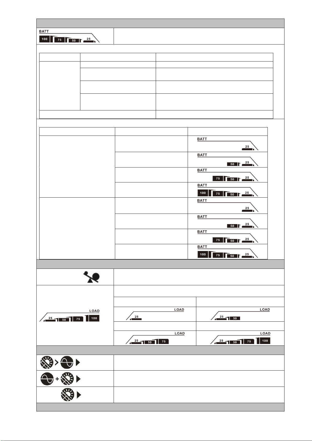
Battery Information
Indicates battery level by 0-24%, 25-49%, 50-74% and 75-100% in
battery mode and charging status in line mode.
When battery is charging, it will present battery charging status.
Status
Battery voltage
LCD Display
Constant
Current mode /
Constant
Voltage mode
<2V/cell
4 bars will flash in turns.
2 ~ 2.083V/cell
The right bar will be on and the other three bars
will flash in turns.
2.083 ~ 2.167V/cell
The right two bars will be on and the other two
bars will flash in turns.
> 2.167 V/cell
The right three bars will be on and the left bar
will flash.
Floating mode. Batteries are fully charged.
4 bars will be on.
In battery mode, it will present battery capacity.
Load Percentage
Battery Voltage
LCD Display
Load >50%
< 1.85V/cell
1.85V/cell ~ 1.933V/cell
1.933V/cell ~ 2.017V/cell
> 2.017V/cell
Load < 50%
< 1.892V/cell
1.892V/cell ~ 1.975V/cell
1.975V/cell ~ 2.058V/cell
> 2.058V/cell
Load Information
Indicates overload.
Indicates the load level by 0-24%, 25-49%, 50-74% and 75-100%.
0%~24%
25%~49%
50%~74%
75%~100%
Charger Source Priority Setting Display
Indicates setting program 16 “Charger source priority” is selected as
“Solar first”.
Indicates setting program 16 “Charger source priority” is selected as
“Solar and Utility”.
Indicates setting program 16 “Charger source priority” is selected as
“Solar only”.
Output source priority setting display
15
Indicates setting program 01 “Output source priority” is selected as
“Utility first”.
Indicates setting program 01 “Output source priority” is selected as
“Solar first”.
Indicates setting program 01 “Output source priority” is selected as
“SBU”.
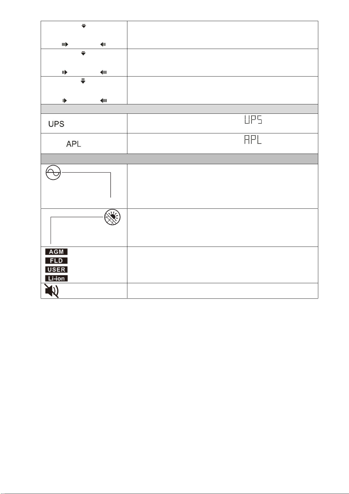
AC Input Voltage Range Setting Display
Indicates setting program 03 is selected as “ ”. The acceptable AC
input voltage range will be within 170-280VAC.
Indicates setting program 03 is selected as “ ”. The acceptable AC
input voltage range will be within 90-280VAC.
Operation Status Information
Indicates unit connects to the mains.
Indicates unit connects to the PV panel.
Indicates battery type.
Indicates unit alarm is disabled.
16
LCD Setting
After pressing and holding ENTER button for 3 seconds, the unit will enter setting mode. Press “UP”or “DOWN”
button to select setting programs. And then, press “ENTER”button to confirm the selection or ESC button to
exit.
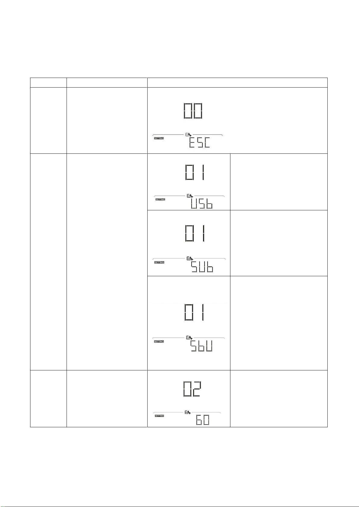
Setting Programs:
Program
Description
Selectable option
00
Exit setting mode
Escape
01
Output source priority:
To configure load power
source priority
Utility first (default)
Utility will provide power to the
loads as first priority.
Solar and battery energy will
provide power to the loads only
when utility power is not available.
Solar first
Solar energy provides power to
the loads as first priority.
If solar energy is not sufficient to
power all connected loads, Utility
energy will supply power to the
loads at the same time.
SBU priority
Solar energy provides power to
the loads as first priority.
If solar energy is not sufficient to
power all connected loads, battery
energy will supply power to the
loads at the same time.
Utility provides power to the loads
only when battery voltage drops
to either low-level warning voltage
or the setting point in program 12.
02
Maximum charging current:
To configure total charging
current for solar and utility
chargers.
(Max. charging current =
utility charging current +
solar charging current)
60A (default)
Setting range is from 10A to 100A.
Increment of each click is 10A.

17
03
AC input voltage range
Appliances (default)
If selected, acceptable AC input
voltage range will be within
90-280VAC.
UPS
If selected, acceptable AC input
voltage range will be within
170-280VAC.
05
Battery type
AGM (default)
Flooded
User-Defined
If “User-Defined”is selected,
battery charge voltage and low DC
cut-off voltage can be set up in
program 26, 27 and 29.
06
Auto restart when overload
occurs
Restart disable (default)
Restart enable
07
Auto restart when over
temperature occurs
Restart disable (default)
Restart enable
09
Output frequency
50Hz (default)
60Hz

18
10
Output voltage
220V
230V (default)
240V
11
Maximum utility charging
current
Note: If setting value in
program 02 is smaller than
that in program in 11, the
inverter will apply charging
current from program 02 for
utility charger.
30A (default)
Setting range is 2A, then from 10A
to 100A. Increment of each click is
10A.
12
Setting voltage point back
to utility source when
selecting “SBU” (SBU
priority) in program 01.
Available options in 3.6KW model:
23.0V (default)
Setting range is from 22V to
25.5V. Increment of each click is
0.5V.
Available options in 5.6KW model:
46V (default)
Setting range is from 44V to 51V.
Increment of each click is 1V.
13
Setting voltage point back
to battery mode when
selecting “SBU” (SBU
priority) in program 01.
Available options in 3.6KW model:
Battery fully charged
27V (default)
Setting range is from 24V to 29V. Increment of each click is 0.5V.

19
13
Setting voltage point back
to battery mode when
selecting “SBU” (SBU
priority) in program 01.
Available options in 5.6KW model:
Battery fully charged
54V (default)
Setting range is from 48V to 58V. Increment of each click is 1V.
16
Charger source priority:
To configure charger
source priority
Solar first
Solar energy will charge battery as
first priority.
Utility will charge battery only
when solar energy is not available.
Solar and Utility (default)
Solar energy and utility will charge
battery at the same time.
Only Solar
Solar energy will be the only
charger source no matter utility is
available or not.
If this inverter/charger is working in Battery mode, only solar
energy can charge battery. Solar energy will charge battery if it's
available and sufficient.
18
Alarm control
Alarm on (default)
Alarm off
This manual suits for next models
1
Table of contents
Other Crown Micro Inverter manuals


