Santon DFS-14 User manual

20140625_DFS manual V1.2.indd 1 19-08-14 14:40
INSTALLATION MANUAL
INSTALLATIONSHANDBUCH
MANUEL D’INSTALLATION
EN
DE
FR

2
CONTENT / INHALT / CONTENU
CONTENT / INHALT / CONTENU 2
GENERAL NOTICE AND SAFETY INSTRUCTIONS 5
ALLGEMEINE UND SICHERHEITSHINWEISE 6
AVIS ET CONSIGNES GÉNÉRALES DE SÉCURITÉ 7
INSTALLATION DFS / INSTALLATION DFS / INSTALLATION DFS 8
INSTALLATION PFS / INSTALLATION PFS / INSTALLATION PFS 10
SPECIFICATIONS (IEC) / SPEZIFIKATIONEN (IEC) /
FICHE TECHNIQUE (IEC) 12

DFS-14
• Motor driven DC disconnect switch in enclosure
• Installation manual
DFS-14-W
• Motor driven DC disconnect switch in enclosure
• Installation manual
• 9 x M12 glands
DFS-14-MC4
• Motor driven DC disconnect switch in enclosure
• Installation manual
• Pre-wired on 8 x MC4 connectors (org. STÄUBLI)
• 1 x M12 gland
DFSHP-14-MC4
• Motor driven DC disconnect switch in enclosure
• Installation manual
• Pre-wired on 8 x MC4 connectors (org. STÄUBLI)
• 1 x M12 gland
DFSHP-154-MC4-Evo2
• Motor driven DC disconnect switch in enclosure
• Installation manual
• Pre-wired on 8 x MC4-Evo2 connectors
(org. STÄUBLI)
• 1 x M12 gland
3
CONTENT / INHALT / CONTENU

4
PFSHP-18-MC4
• Motor driven DC disconnect switch in enclosure
• Installation manual
• Pre-wired on 16 x MC4 connectors (org. STÄUBLI)
• 1 x M20 gland
PFSHP-158-MC4-Evo2
• Motor driven DC disconnect switch in enclosure
• Installation manual
• Pre-wired on 16 x MC4-Evo2 connectors
(org. STÄUBLI)
• 1 x M20 gland
PFSHP-18S-MC4
• Motor driven DC disconnect switch in enclosure
• Installation manual
• Pre-wired on 16 x MC4 connectors (org. STÄUBLI)
• On connectors pre-wired auxillary contact
(change over)
• 1 x M20 gland
PFSHP-158S-MC4-Evo2
• Motor driven DC disconnect switch in enclosure
• Installation manual
• Pre-wired on 16 x MC4-Evo2 connectors
(org. STÄUBLI)
• On connectors pre-wired auxillary contact
(change over)
• 1 x M20 gland
CONTENT / INHALT / CONTENU

General notice
• Changes or modications not explained/approved in this manual voids your authority to operate this
equipment.
• Santon shall not be held responsible for any damage caused due to incorrect installation of the product and/or the
misunderstanding of this manual.
• Santon reserves the right to make any modication to this manual or the information contained herein at any time
without notice.
• No design data such as sample pictures provided in this manual may be modied or duplicated except for the purpose
of personal use.
• To ensure the recycling of all possible materials and proper disposal treatment of components, please return the
product to Santon at end-of-life.
• Check the system regularly (once per 3 months) on faults.
Important safety precautions
Attention! Components in the installations are exposed to high voltages and currents. Follow these instructions carefully
in order to reduce the risk of re or electric shock.
The following regulations and standards are considered applicable and mandatory to read prior to the installati-
on of electrical equipment:
• International Standards: IEC 60364-7-712 Electrical installations of buildings – Requirements for special installations or
locations – Solar Photovoltaic (PV) power supply systems
• MIS3002: Microgeneration Installation Standard - requirements for contractors undertaking the supply, design,
installation, set to work commissioning and handover of solar photovoltaic (PV) microgeneration systems
• Local building regulations
• Guidelines for lightning and overvoltage protection
Note!
• It is essential to uphold the limits for voltage and current in all possible operating conditions (see page 12; ‘Technical
Data’). Also keep in mind the literature on correct dimensioning and sizing of cabling and components.
• The installation of these devices may only be performed by certied technical personnel.
• The wiring schematics of the Fireghter safety Switch can be founde at the end of this manual.
• All the installation works should be tested in accordance with relevant local legislation at the time of installation.
Intended use of the Fireghter safety Switch
The Fireghter safety Switch (DFS / PFS) has been especially developed as a safety device for direct current (DC)
photovoltaic installations. The DC disconnect switch is used to disconnect the connected strings of the installation in
case of an emergency situation. Such an emergency situation could be in case of re.
Location of the Fireghter Safety Switch
The DFS / PFS needs to be placed as close to the solar panels as possible. Due to its enclosure, the switch is protected
against external inuences like dust and moisture. The whole set-up is conform to IP65 which make it suitable for
outdoor usage when needed.
NOTE: The switch enclosure may not be installed in direct sunlight or be in direct contact with (continuous) water ingress.
Normal operation:
The DFS / PFS will automatically switch to the off position, breaking the DC connection between the solar panels and the
inverter, after the AC power to the DFS / PFS is interrupted for longer than 0,5 seconds. The DFS / PFS will automatical-
ly switch to the on position, restoring the DC connection between the solar panels and the inverter, once the AC power to
the DFS / PFS is restored longer than ve seconds.
Special Operation:
If the temperature inside the DFS / PFS enclosure exceeds the 100°C, the DFS / PFS will automatically switch to OFF to
protect the internal components and create a safe situation. When the installation is checked and the DFS / PFS is not
affected, the DFS / PFS can be switched ON again by removal and re-applying the AC voltage to the DFS / PFS. The
DFS / PFS will also automatically switch to OFF if there is an internal failure. If this occurs please try to reset the DFS /
PFS by removal and re-applying the AC voltage to the DFS / PFS.
If this problem remains, please contact the Santon Support team: solar@santonswitchgear.com
GENERAL NOTICE AND SAFETY INSTRUCTIONS
5

6
Allgemeiner Hinweis
• Änderungen oder Modikationen, die in diesem Handbuch nicht erklärt/genehmigt werdern, führen dazu, dass Sie
dieses Gerät nicht mehr bedienen dürfen.
• Santon ist nicht haftbar für Schäden, die durch falsche Installation des Produkts und/oder falschem Verstehen dieses
Handbuchs entstehen.
• Santon behält sich das Recht vor, jederzeit und ohne Vorankündigung Änderungen an diesem Handbuch oder den
darin enthaltenen Informationen vorzunehmen.
• In diesem Handbuch enthaltene Konstruktionsdaten wie Beispielbilder dürfen nicht modiziert oder vervielfältigt
werden, außer für persönliche Zwecke.
• Geben Sie das Produkt am Ende der Lebensdauer bitte an Santon zurück, um ein Recycling der verwertbaren
Materialien und die ordnungsgemäße Entsorgung der Komponenten sicherzustellen.
• Überprüfen Sie das System regelmäßig (alle 3 Monate) auf Fehler.
Wichtige Sicherheitsvorkehrungen
Achtung! Komponenten in den Anlagen sind hohen Spannungen und Strömen ausgesetzt. Befolgen Sie die
Anweisungen sorgfältig, um Brandrisiko oder die Gefahr eines Stromschlags zu reduzieren.
Die folgenden Regulierungen und Standards werden als anwendbar angesehen und müssen vor der Installation
des elektrischen Geräts gelesen werden:
• Internationale Standards: IEC 60364-7-712 Elektrische Installationen von Gebäuden - Anforderungen für spezielle
Installationen oder Orte – Solar Photovoltaik (PV) Energieversorgungssysteme
• MIS3002: Microgeneration Installation Standard - Anforderungen für Bauunternehmer, die für Lieferung, Entwurf, Installation,
Inbetriebnahme und Übergabe von Solar Photovoltaik (PV) Mikro-Energieerzeugungssystemen zuständig sind
• Örtliche Bauvorschriften
• Richtlinien für Blitz- und Überspannschutz
Hinweis!
• Es ist unabdingbar, sich unter allen möglichen Betriebsbedingungen an die Grenzen für Spannung und Strom zu halten
(siehe Seite 12, „Technische Daten“). Beachten Sie auch die Literatur zu richtiger Dimensionierung und Auslegung der
Verkabelung und von Komponenten.
• Die Installation dieser Geräte darf nur von zertiziertem technischen Personal durchgeführt werden.
• Der Schaltplan des Haus-Feuerwehrschutzschalters bendet sich am Ende dieses Handbuchs.
• Alle Installationsarbeiten müssen entsprechend der relevanten örtlichen Gesetzgebung zum Zeitpunkt der Installation
getestet werden.
Verwendungszweck des Feuerwehr Sicherheitsschalters
Der Feuerwehrsicherheitsschalter (DFS / PFS) wurde speziell als Schutzvorrichtung für Gleichstrom (DC) Fotovoltaikan-
lagen entwickelt. Der Stromtrennschalter wird verwendet, um in Notfällen die angeschlossenen Kabel von der Anlage zu
trennen. Eine solche Notsituation kann ein Feuer sein.
Lage des Feuerwehr Sicherheitsschalters
Der DFS / PFS muss so nahe wie möglich an den Solarpaneelen angebracht werden. Aufgrund seines Gehäuses ist der
Schalter vor äußeren Einüssen wie Staub und Feuchtigkeit geschützt. Die gesamte Einrichtung entspricht IP65,
sodass sie bei Bedarf auch im Freien verwendet werden kann. HINWEIS: Das Schaltergehäuse darf nicht in direktem
Sonnenlicht installiert werden oder (ständig) mit eindringendem Wasser in Kontakt kommen.
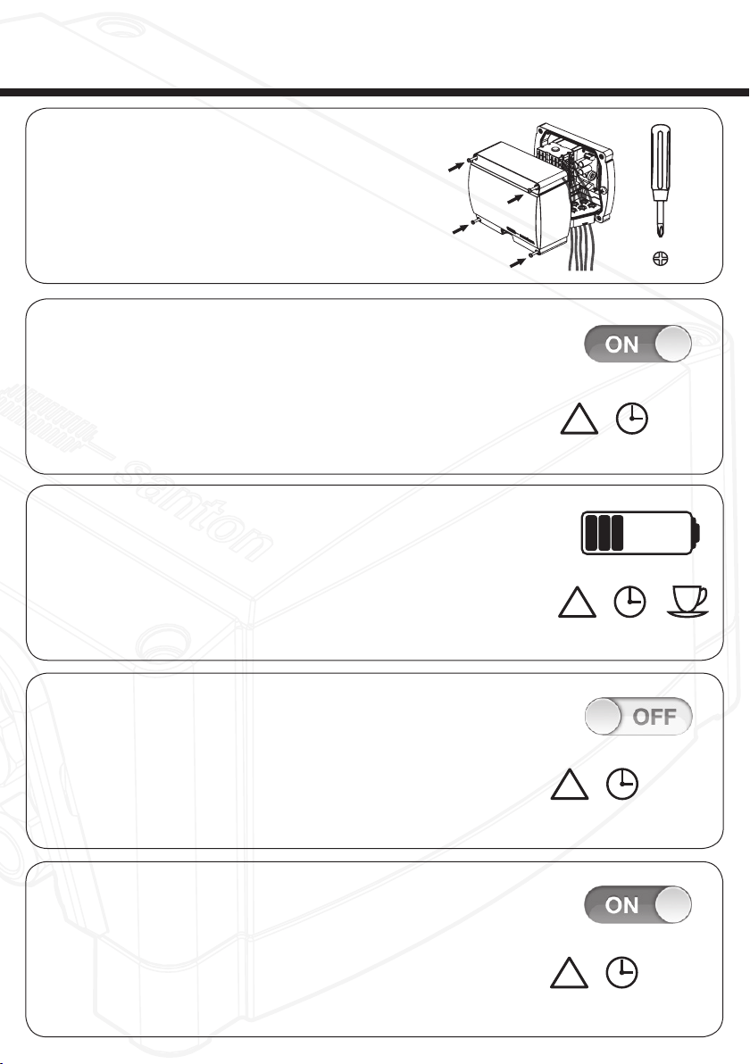
Normaler Betrieb:
Der DFS / PFS schaltet automatisch in die Aus-Position und unterbricht die Gleichstromverbindung zwischen den
Solarpaneelen und dem Umrichter, wenn die Wechselspannung des DFS / PFS für länger als 0,5 Sekunden unterbro-
chen ist. Der DFS / PFS schaltet automatisch in die An-Position und stellt die Gleichstromverbindung zwischen den
Solarpaneelen und dem Umrichter wieder her, wenn die Wechselspannung des DFS / PFS für länger als 5 Sekunden
wiederhergestellt ist.
Spezialbetrieb:
Wenn die Temperatur im DFS / PFS-Gehäuse 100°C überschreitet, schaltet der DFS / PFS zum Schutz der eingebauten
Komponenten automatisch auf OFF und stellt so eine sichere Situation her. Wenn die Installation überprüft wird und
der DFS / PFS nicht betroffen ist, kann der DFS / PFS wieder auf ON geschaltet werden, indem die Wechselspannung
vom DFS / PFS weggenommen und wieder zugeführt wird. Der DFS / PFS schaltet auch dann automatisch auf OFF,
wenn ein interner Fehler auftritt. Wenn das geschieht, versuchen Sie bitte den DFS / PFS zurückzusetzen, indem Sie die
Wechselspannung vom DFS / PFS wegnehmen und wieder zuführen.
Wenn das Problem weiterhin besteht, nehmen Sie bitte Kontakt mit dem Santon Support Team auf:
solar@santonswitchgear.com
ALLGEMEINE UND SICHERHEITSHINWEISE

Avis général
• Les changements ou modications non expliquées/non reconnues dans ce manuel annulent votre droit d’utiliser cet
équipement.
• Santon ne pourra être tenu pour responsable de tout dommage provoqué en raison d’une installation incorrecte du
produit et/ou d’un malentendu lié à ce manuel.
• Santon se réserve le droit de modier ce manuel ou les informations contenues dans ce dernier à tout moment,
sans avis préalable.
• Aucune donnée de conception, telle que des photos d’exemples fournies dans ce manuel, ne peut être modiée ou
reproduite à des ns d’utilisation personnelle.
• Veuillez retourner le produit en n de vie à Santon, an d’assurer le recyclage de tous les matériaux possibles ainsi que
l’élimination appropriée des composants.
• Inspectez régulièrement le système (une fois tous les 3 mois) an que de repérer les éventuels dysfonctionnements.
Importantes consignes de sécurité
Attention ! Les composants de l’installation sont soumis à des tensions et des courants élevés. Suivez ces instructions
attentivement an de réduire les risques d’incendie ou de choc électrique.
Les législations et normes suivantes sont considérées comme applicables et impératives à lire avant
l’installation de l’équipement électrique :
• Normes internationales : CEI 60364-7-712 Installations électriques des bâtiments - Règles pour les installations et
emplacements spéciaux – Alimentations photovoltaïques solaires (PV)
• MIS3002: Normes d’installation de micro-cogénération - exigences pour les entrepreneurs effectuant la fourniture, la
conception, l’installation, la mise en service et la remise des systèmes de micro-cogénération d’énergie solaire
photovoltaïque (PV)
• Réglementations locales relatives aux bâtiments
• Directives sur l’éclairage et la protection contre la surtension
Remarque !
• Il faut impérativement respecter les limites imposées en termes de tension et d’intensité dans toutes les conditions
de fonctionnement possible (voir page 12 : « Caractéristiques techniques »). Il convient aussi de ne pas oublier les
publications relatives au dimensionnement et à la détermination des tailles correctes des câbles et des composants.
• L’installation de ces dispositifs doit être strictement réservée à un personnel technique agréé.
• Vous trouverez les schémas de câblage de l’interrupteur de sécurité anti-incendie domestique à la n de ce manuel.
• Tous les travaux d’installation doivent être testés conformément à la législation locale en vigueur au moment de
l’installation.
Utilisation prévue de l’interrupteur de sécurité anti-incendie
L’interrupteur de sécurité anti-incendie (DFS / PFS) est un dispositif de sécurité spécialement mis au point pour les installati-
ons photovoltaïques à courant continu (CC). Le sectionneur CC est utilisé pour déconnecter les câbles branchés de l’installati-
on en cas de situation urgente. Une situation d’urgence de ce type pourrait se présenter en cas d’incendie.
Emplacement de l’interrupteur de sécurité anti-incendie
L’interrupteur de sécurité anti-incendie doit être placé aussi près que possible des panneaux solaires.
L’interrupteur est protégé des inuences externes (comme la poussière et l’humidité) grâce à son boîtier. Toute la
structure est conforme à IP65 et fait que l’appareil peut être utilisé à l’extérieur, le cas échéant.
REMARQUE: Le boîtier de l’interrupteur ne peut pas être placé à la lumière directe du soleil ou en contact direct avec de
l’eau qui pénètre (en permanence).
Fonctionnement normal :
L’interrupteur de sécurité anti-incendie domestique se mettra automatiquement en position arrêt, coupant la connexion
CC entre les panneaux solaires et l’onduleur, après que le courant CA vers l’interrupteur de sécurité a été interrompu
pendant plus de 0,5 secondes. L’interrupteur de sécurité anti-incendie domestique se mettra automatiquement en
position marche, rétablissant la connexion CC entre les panneaux solaires et l’onduleur, après que le courant CA vers
l’interrupteur de sécurité a été rétabli pendant plus de cinq secondes.
Fonctionnement spécial :
Si la température à l’intérieur de l’enceinte DFS / PFS dépasse les 100°C, celle-ci bascule automatiquement sur OFF
pour protéger les composants internes et créer une situation sûre. Lorsque l’installation est vériée et que la DFS / PFS
n’est oas affectée, elle peut être remise en marche par la mise hors tension, puis sous tension de la tension alternative
allant vers la DFS / PFS. La DFS / PFS basculera aussi automatiquement sur OFF s’il y a une défaillance interne. Si
cela se produit, veuillez essayer de réinitialiser la DFS / PFS par la mise hors tension, puis sous tension de la tension
alternative allant vers la DFS / PFS. Si ce problème persiste, veuillez contacter l’équipe d’assistance Santon:
solar@santonswitchgear.com
AVIS ET CONSIGNES GÉNÉRALES DE SÉCURITÉ
7

7.
Close the switch enclosure
Montieren Sie wieder den Gehäusedeckel
Fermez le boîtier de l’interrupteur
9. TEST
Wait one minute. UPS is charging.
Warten Sie eine Minute. UPS wird aufgeladen.
Attendez une minute. UPS est en charge.
10. TEST
Turn off AC power circuit. DFS... will switch off.
Deaktivieren Sie den Netzstromkreis. DFS... wird abgeschaltet.
Désactiver le circuit d’alimentation. DFS... s’éteint.
Approx. 1,5 sec.
!
Approx. 1 min.
!
8. TEST
Turn on AC power circuit. DFS... switches on.
Aktivieren Sie den Netzstromkreis. DFS... schaltet ein.
Activez le circuit d’alimentation. DFS... met en marche.
11.
Turn on AC power circuit. DFS... switches on. You’re done!
Aktivieren Sie den Netzstromkreis. DFS... schaltet ein. Sie sind fertig!
Activez le circuit d’alimentation. DFS... met en marche. Vous avez terminé!
Approx. 5 sec.
!
Approx. 5 sec.
!
M4 (4x) - Max. 1.7Nm
20140625_DFS manual V1.2.indd 10 19-08-14 14:40
1.
Installation requirements
Installationsanforderungen
Conditions requises pour l’installation
2.
Remove the lid from the enclosure
Entfernen Sie den Deckel vom Schaltergehäuseboden
Ôtez le couvercle du boîtier de l’interrupteur
3.
Mount the switch enclosure on the wall
Montieren Sie den Boden des Gehäuses an der Wand
Fixez le boîtier de l’interrupteur au mur
4.
Wire the power connection to the terminals
Verbinden Sie den Netzanschluss an den Klemmen
Type de connexion d’alimentation pour les bornes
5. ONLY DFS-14 and DFS-14-W
Wire the string cables to the switch
Schließen Sie die Gleichstromkabel an den Schalter an
Branchez les câbles de chaîne à l’interrupteur
6. FOR ALL DFS with MC4 and MC4-Evo2 connectors
MC4 (original Stäubli)
Connect the string cables to the MC4 connectors on the DFS...-MC4
Verbinden Sie die Stringkabel mit den MC4 Steckern des DFS...-MC4
Connectez les Câbles de string aux connecteurs MC4 du DFS...-MC4
!
M4
!
(2x)
!
Max. 1.7Nm
M4
8
*Screws
not included
*Minimal
4mm²
INSTALLATION DFS / INSTALLATION DFS / INSTALLATION DFS

7.
Close the switch enclosure
Montieren Sie wieder den Gehäusedeckel
Fermez le boîtier de l’interrupteur
9. TEST
Wait one minute. UPS is charging.
Warten Sie eine Minute. UPS wird aufgeladen.
Attendez une minute. UPS est en charge.
10. TEST
Turn off AC power circuit. DFS... will switch off.
Deaktivieren Sie den Netzstromkreis. DFS... wird abgeschaltet.
Désactiver le circuit d’alimentation. DFS... s’éteint.
Approx. 1,5 sec.
!
Approx. 1 min.
!
8. TEST
Turn on AC power circuit. DFS... switches on.
Aktivieren Sie den Netzstromkreis. DFS... schaltet ein.
Activez le circuit d’alimentation. DFS... met en marche.
11.
Turn on AC power circuit. DFS... switches on. You’re done!
Aktivieren Sie den Netzstromkreis. DFS... schaltet ein. Sie sind fertig!
Activez le circuit d’alimentation. DFS... met en marche. Vous avez terminé!
Approx. 5 sec.
!
Approx. 5 sec.
!
M4 (4x) - Max. 1.7Nm
20140625_DFS manual V1.2.indd 10 19-08-14 14:40
9

1.
Installation requirements
Installationsanforderungen
Conditions requises pour l’installation
2.
Remove the lid from the enclosure
Entfernen Sie den Deckel vom Schaltergehäuseboden
Ôtez le couvercle du boîtier de l’interrupteur
3.
Mount the switch enclosure on the wall
Montieren Sie den Boden des Gehäuses an der Wand
Fixez le boîtier de l’interrupteur au mur
4. FOR ALL PFS with MC4 and MC4-Evo2
connectors MC4 (original Stäubli)
Wire the power connection to the terminals
Connect the string cables to the MC4 connectors on the PFS...-MC4
Verbinden Sie den Netzanschluss an den Klemmen
Verbinden Sie die Stringkabel mit den MC4 Steckern des PFS...-MC4
Type de connexion d’alimentation pour les bornes
Connectez les Câbles de string aux connecteurs MC4 du PFS...-MC4
5.
Close the switch enclosure
Montieren Sie wieder den Gehäusedeckel
Fermez le boîtier de l’interrupteur
L N E
10
* 4 x Wall
mounting
screws
not included
Inbus 5
INSTALLATION PFS / INSTALLATION PFS / INSTALLATION PFS

6. TEST
Turn on AC power circuit. PFS... switches on.
Aktivieren Sie den Netzstromkreis. PFS... schaltet ein.
Activez le circuit d’alimentation. PFS... met en marche.
7. TEST
Wait one minute. UPS is charging.
Warten Sie eine Minute. UPS wird aufgeladen.
Attendez une minute. UPS est en charge.
8. TEST
Turn off AC power circuit. PFS... will switch off.
Deaktivieren Sie den Netzstromkreis. PFS... wird abgeschaltet.
Désactiver le circuit d’alimentation. PFS... s’éteint.
9.
Turn on AC power circuit. PFS... switches on. You’re done!
Aktivieren Sie den Netzstromkreis. PFS... schaltet ein. Sie sind fertig!
Activez le circuit d’alimentation. PFS... met en marche. Vous avez terminé!
11
Approx. 1,5 sec.
!
Approx. 1 min.
!
Approx. 5 sec.
!
Approx. 5 sec.
!

DFS-14...* DFSHP-14-MC4 DFSHP-154-MC4(Evo2)
String Voltages (Vdc) 1000 850 800 650 1000 1000 1500
String Current (A) 16 20 25 32 40 45 20
Switch version 4 poles, 0-1-0-1 4 poles, 0-1-0-1 4 poles, 0-1-0-1
Number of Strings 2 2 2
Operating Voltage 100Vac - 240Vac
Nominal Voltage 230Vac
Nominal Current 30mA
Start up (loading) Current average 100mA
Switch on Action Current max 300mA
Feedback contact 24Vdc - 300mA max
Optional Auxilary contact IEC
60947 AC-15 / DC-13 N/A
max. switching voltage
max. switching current
Operating Temperature range -20°C - +50°C
Maximum operating temperature
before automatic switch OFF +100°C
Storage Temperature range -40°C - +85°C
Protection Degree IP65
Protection Level Class II
Weight Approx. 1kg
CE certication EN 60947 part 1+3
DC Switch disconnect according to IEC: EN 60947-3:2009/A1:2012/C1:2013 /A2:2015 Cat PV -1
Number of operations without current 9700
Number of operations under load
(PV-1) with current 300
* For DFS-14 and DFS-14-W please use correct M4 fork cable lugs shoes / Für DFS-14 und DFS-14-W nutzen Sie bitte
korrekte M4 Gabel Kabelschuhe / Pour DFS-14 et DFS-14-W s’il vous plaît utiliser cosse M4 correcte / Para DFS-14 y
DFS-14-W por favor, utilice correcta terminal de cable M4 / Per DFS-14 e DFS-14-W si prega di utilizzare corretta
capacorda M4 / Gebruik voor de DFS-14 en DFS-14-W de correc te M4 kabelschoen.
12
175
210
175
105
187
105
210
SPECIFICATIONS (IEC) / SPEZIFIKATIONEN (IEC) / FICHE TECHNIQUE (IEC)

13
PFSHP-18-MC4 PFSHP-158-MC4(Evo2) PFSHP-18S-MC4 PFSHP-158S-MC4(Evo2)
1000 1000 1500 1000 1000 1500
45 45 20 45 45 20
8 poles, 0-1-0-1 8 poles, 0-1-0-1 8 poles, 0-1-0-1 8 poles, 0-1-0-1
4444
100Vac - 240Vac
230Vac
30mA
average 100mA
max 300mA
24Vdc - 300mA max
N/A Change over contact Change over contact
AC-15: 230 V | DC-13: 60 V AC-15: 230 V | DC-13: 60 V
1.0 A | 0.5 A 1.0 A | 0.5 A
-20°C - +50°C
+100°C
-40°C - +85°C
IP65
Class II
EN 60947 part 1+3
IEC: EN 60947-3:2009/A1:2012/C1:2013 /A2:2015 Cat PV -1
9700
300
122
300
240
226
231
(INCL. MC4 CONNECTORS)
265
125

WIRING DFS / VERDRAHTUNG DFS / CÂBLAGE DFS
E
DFS-14 / DFS-14-W / DFS-14-MC4 / DFSHP-14-MC4
DFSHP-154-MC4 (EVO2)
Electrical connection drawing for 2 string units
*Emergency
stop button
latching
*All switches are
NC-contacts and
shown in the
actuated state.
None of the
switches shown in
this circuit
diagram are
supplied with the
DFS/PFS units.
These are only
used to illustrate
how a circuit can
be opened in
orderto activate
the DFS/PFS
units in the event
of afire.
Which type of
switch is used, is
up tothe installer
and the number of
interruption points
does not matter,
as long as they
are connected in
series and each
individual isolater
interrupts the AC-
power supply to
the DFS/PFS
units in the event
of afire.
N
L
4 pole / 2strings DFS
switch DC contacts are
switched on when AC
power is applied
Aux. Contact max. 24V
4 pole / 2strings DFS
switch DC contacts are
switched on when AC
power is applied
Aux. Contact max. 24V
L
N
11
4 pole / 2strings DFS
switch DC contacts are
switched on when AC
power is applied
Aux. Contact max. 24V
13
+1
14
-2
+2
*Float
switch
4 pole / 2strings DFS switch
DC contacts are switched on
when AC power is applied
AC-Grid
-2
*Circuit
breaker
L
N
-1
12
DFS
+2
-1
+1
DFS
UPS
L
N
Aux. contact
max. 24V
DFS
M
+
-
L
N
DFS
FB
FB
FB
FB
FB
FB
14

PFSHP-18-MC4 / PFSHP-18S-MC4
PFSHP-158-MC4(EVO2) / PFSHP-158S-MC4(EVO2)
Electrical connection drawing for 4 string units
*
Emergency
stop button
latching
*All switches are
NC-contacts and
shown in the
actuated state.
None of the
switches shown in
this circuit
diagram are
supplied with the
DFS/PFS units.
These are only
used to illustrate
how a circuit can
be opened in
order to activate
the DFS/PFS
units in the event
of a fire.
Which type of
switch is used, is
up to the installer
and the number of
interruption points
does not matter,
as long as they
are connected in
series and each
individual isolater
interrupts the AC-
power supply to
the DFS/PFS
units in the event
of a fire.
Optionally, it is possible to
get the PFS switches with
a changeover auxiliary
contact.
The auxiliary contact is
designed for 230V AC with
a current of 1 A
PFS switch 8 poles / 4 strings pre-
wired to MC4 connectors (original
Stäubli)
DC contacts are switched on
when AC power is applied.
PFSHP
L
21
22
24
*Float
switch
L
*Circuit
breaker
AC-Grid
N
Optionally, it is possible to
get the PFS switches with
a changeover auxiliary
contact.
The auxiliary contact is
designed for 230V AC with
a current of 1 A
21
22
24
PFSHP
PFS switch 8 poles / 4 strings pre-
wired to MC4 connectors (original
Stäubli)
DC contacts are switched on
when AC power is applied.
N
PFSHP
PFS switch 8 poles / 4 strings pre-
wired to MC4 connectors (original
Stäubli)
DC contacts are switched on
when AC power is applied.
L
N
15
WIRING PFSHP / VERDRAHTUNG PFSHP / CÂBLAGE PFSHP

info@santonswitchgear.com, www.santonswitchgear.com, NEN-EN-ISO 9001:2015
© copyrights Santon International bv
Article: 90A1502.00 | 11-2021
20140625_DFS manual V1.2.indd 12 19-08-14 14:40
This manual suits for next models
8
Table of contents
Languages:
Other Santon Safety Equipment manuals
Popular Safety Equipment manuals by other brands

Metacon-Next
Metacon-Next RGS EI-30 user manual

BlueWear
BlueWear 003624 operating instructions

Reer
Reer Mosaic MCT1 Quick installation guide

TOOLCRAFT
TOOLCRAFT 1437615 operating instructions

TIE DOWN
TIE DOWN Parapet Anchor instruction manual

Jet EQUIPMENT & TOOLS
Jet EQUIPMENT & TOOLS JLP Series owner's manual