Lewmar OVERSIDE WORK RAIL SYSTEM Quick start guide

OVERSIDE WORK RAIL SYSTEM
SIZE 1
Installation, Use and Servicing Manual
Part No B10465- iss.1 (Feb. 2016)
GB

LEWMAR OVERSIDE WORK RAIL SYSTEM SIZE 1
1. Introduction
2. Description and Purpose
3. Rating
4. System Specification
5. System Components
6. Part Numbers
7. Installation
8. Use
9. Maintenance and Thorough Examination
10. External Documents
11. System Component Drawings
12. Warranty
Contents

OVERSIDE WORK RAIL SYSTEM SIZE 1 - B10465 iss.1 | 3
Please read these instructions carefully before installing, operating or servicing this equipment. These
instructions MUST be provided to the user of this equipment. The user must read and understand the
instructions before using this equipment. Manufacturer’s instructions must be followed to ensure correct use and
maintenance of this equipment. Alterations or misuse of this equipment, or failure to follow these instructions,
may result in a fall or failure to arrest a fall leading to serious injury or death.
PLEASE RETAIN THESE INSTRUCTIONS
1 - Introduction
Thank you for choosing Lewmar. Lewmar products are world renowned for their quality, technical innovation and
proven performance. With a Lewmar product you will be provided with many years of outstanding service.
Important information about this manual
Throughout this manual, you will see safety and product damage warnings.
You must follow these warnings carefully to avoid possible injury or damage.
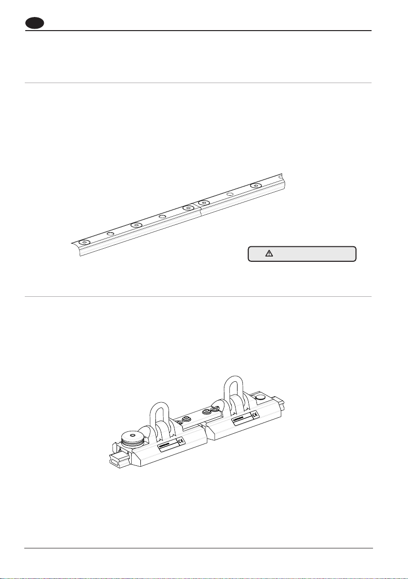
2 - Description and Purpose
WARNING!
The Lewmar Overside Work Rail System is a personal suspension system for the liing, lowering and traversing
of persons performing maintenance operations. It enables safe access whilst working at height. It is not to be
used for liing equipment or any other purpose.
This system is CE-certified and has been successfully tested against the requirements in European standard EN
795 Class D editions 1996 and 2012. It has also been successfully tested against the requirements in Lewmar
Test specification TS-LEW-15, which was specifically developed for testing personal suspension systems,
including rescue, and specifies requirements well in excess of those found in EN 795.
The system consists of aluminium track sections which are joinable to form a continuous span of rail. This is
fixable to a structure in the horizontal plane, whether that structure is part of a sea vessel, building, steelwork,
air or land vehicle or the like and the course of the rail follows the contour of the structure to which it is fixed.
Cars can be engaged on and can slide along the rail. End-stops are fixed to the ends of the rail span to prevent
inadvertent disengagement of the cars.
A person may li or lower themselves in the vertical plane by attaching a liing-lowering device and rope to the
shackle of a car, together with a seat or support harness. Also, they may traverse horizontally from one position
to another along the span of the rail by virtue of the car’s sliding capability.
Consequently, suspended access can be gained to any point below the rail span. This can be extremely useful in
situations where conventional access methods such as ladders and platforms cannot be utilised.
Lewmar tracks and car are not compatible with those of any other manufacture.
Only use CE Certified Lewmar products (Page 6) for overside working.

4
GB
End Stops
M8 fastener holes
Typical locking hole
Car
Rail
Locking Device
Carriage Link
Shackle
Main system components
Fall-Arrest Rope
Fall-Arrest Rope
Optional car and link
for use as a tool carrier
Lifting-Lowering Rope
Cars

OVERSIDE WORK RAIL SYSTEM SIZE 1 - B10465 iss.1 | 5
A device permits the locking of the car to any of the locking holes along the rail, so that when lowering or liing
in the vertical plane, the car does not inadvertently slide along the rail in response to lowering or liing
movement, enabling the person to maintain stability and to control their position.
A second car, which is joined to the main car, provides the attachment point for a fall-arrest system. The
fall-arrest system prevents a fall to the ground, substantial platform, water or other substance should the
liing-lowering device or rope fail. Use of the fall-arrest system necessitates the wearing of a full body safety
harness by the worker.
The rail is also tested and rated for rescue purposes - to allow a second person to lower themselves from an
additional pair of cars on the track in order to rescue a worker whohas become incapacitated, or whose fall has
been arrested and cannot get back to a place of safety on their own.
An additional single car can also be used to secure a small tool bag and containers of cleaning agents, to assist
in any maintenance work.
3 - Rating
In normal operation the system is designed for use by one person with a mass,(including clothing and
attached equipment), not in excess of 125 kg. No more than one person may be connected to a two-car
assembly at any one time. The fall-arrest system must be connected to the car with the spring loaded locking
plunger and the liing-lowering system must be connected to the other car.
In order to assist in the rescue of a person whose fall has been arrested by the fall-arrest system, or has become
incapacitated and is not able to self-recover, a second person may suspend themselves and descend to render
assistance from an additional pair of cars. The system has been tested and has been rated for this situation,
so that two persons, each not in excess of 125 kg, may be attached to the rail in an emergency/rescue
situation.

6
GB
4 - System specification
A system will comprise the following elements:
4.1 Track rail
The rail is low profile and is extruded from 6000 series aluminium, with a hard anodised black finish. The track
rail is secured with M8 countersunk A4-70 stainless steel screws on a 100mm pitch, with car stop plunger
holes spaced 50mm apart from the first fixing, on a100mm pitch. The track rail may be one piece or a multiple
oracks installed in-series, using a joiner insert (2991 5076). Only use designated Lewmar Overside working
tracks.
4.2 One tandem sliding car assembly (two short cars and link plate)
The car is machined from 6000 series aluminium, with a hard anodised black finish. It has recirculating Torlon ball
bearings for free running, low friction performance and low maintenance. The anchor point shackle is forged from
316 grade stainless steel of 8mm diameter, andis free to pivot in a 180 degree arc, 90 degrees each side of the
centre line.
The basic tandem car has two anchor point shackles, one on each car - one anchor point for personal suspension
(overside working) and the second anchor point for fall-arrest.
DO NOT CUT TRACKS

OVERSIDE WORK RAIL SYSTEM SIZE 1 - B10465 iss.1 | 7
4.3 Two End stop
Installed one each at both track rail ends, with 2 x M8 countersunk fixings (supplied), through pre-drilled
holes.
One car body houses the spring plunger assembly - a spring loaded stainless steel plunger with a lock up/down
feature for eitherfree running (‘locked up’ position) or engagement with thetrack to prevent lateral movement,
(‘locked down’position). The locked up position is achieved by pulling the plunger up and twisting. The locked
down position is achieved by positioning the plunger over a locating hole on rail (pre-drilled on a 100 mm pitch)
and twisting to allow plunger to engage hole.
An optional third car can be attached to the tandem car assembly using a link plate kit (2991 3316), for the
purpose of carrying tools (Tool Service Car).
Plunger down, car locked to railPlunger up and locked, car free to
move along rail
Plunger up, car ready to move to
new position

8
GB
4.4 - Product Features
2000 shown (track available in 2m, 3m and 4m lengths (can also be joined)
3
end stop
overhang
265
130
single car
66
66 100.0
100.0
50.0
Ø9.0
Ø9.5
for M8 C'SK
BLIND, FOR PLUNGER
66
(400)
Including optional equipment carrier
293712320BK Sz1 O/S rail track 2m join x2
293712321BK Sz1 O/S rail track 2m end x1 join x1
293712322BK Sz1 O/S rail track 2m end x2
293712330BK Sz1 O/S rail track 3m join x2
293712331BK Sz1 O/S rail track 3m end x1 join x1
293712332BK Sz1 O/S rail track 3m end x2
293712340BK Sz1 O/S rail track 4m join x2
293712341BK Sz1 O/S rail track 4m end x1 join x1
293712342BK Sz1 O/S rail track 4m end x2
See detail A
Typical drilling
Detail A
TRACK JOINER HD
29915076- Sz1 box track joining insert HD (x1)
LINK PLATE
29913316- Sz1 O/S car link plate
ADDITIONAL CAR
Black
29913310BK- Sz1 O/S work car single shackle plunger
29913311BK- Sz1 O/S work car single shackle
3
end stop
overhang
TANDEM CAR
Black
29913313BK- Sz1 O/S work car double
TRACK
Black
END STOP
Black
29915075BK- Sz1 O/S RAIL IM
PACT END

OVERSIDE WORK RAIL SYSTEM SIZE 1 - B10465 iss.1 | 9
5 - System Components
Sz1 Over Side Work Car Double
29913313BK (Black)
Sz1 Over Side Work Car Single Shackle Plunger
29913310BK (Black)
Sz1 Over Side Work Car Single Shackle
29913311BK (Black)
Sz1Over Side Rail Impact End
29915075BK (Black)
Sz1 Over Side Car Link Plate Kit
29915075
Sz1 Joiner Insert HD
29915075
Track
293712320BK / 293712342BK (Black)

10
GB
6 - Sz1 Overside Work Rail Product Part Numbers
Part No. Black Description SWL
(kg)
Length
(mm)
Width (mm) Weight
(g)
29913313BK Sz1 O/S Work Car Double 125 265 66 966
29913310BK Sz1 O/S Work Car Singl Shackle Plunger 125 130 66 476
29913311BK Sz1 O/S Work Car Single Shackle 125 130 66 402
29915075BK Sz1 O/S Rail Impact End 66 66 125
29913316 Sz1 O/S Car Link Plate Kit - - - 88
29915076 Sz1 Joiner Insert HD - - - 29
293712320BK Sz1 O/S Rail Track 2 Mtr Join x2 2000 23 518
293712321BK Sz1 O/S Rail Track 2 Mtr Endx1 Join X1 2000 23 518
293712322BK Sz1 O/S Rail Track 2 Mtr End x2 2000 23 518
293712330BK Sz1 O/S Rail Track 3 Mtr Join x2 3000 23 1038
293712331BK Sz1 O/S Rail Track 3 Mtr Endx1 Join X1 3000 23 1038
293712332BK Sz1 O/S Rail Track 3 Mtr End x2 3000 23 1038
293712340BK Sz1 O/S Rail Track 4 Mtr Join x2 4000 23 2081
293712341BK Sz1 O/S Rail Track 4 Mtr Endx1 Join X1 4000 23 2081
293712342BK Sz1 O/S Rail Track 4 Mtr End x2 4000 23 2081
Lewmar tracks and car are not compatible with those
of any other manufacture. Only use CE Certified Lewmar
products (Page 6) for overside working.

OVERSIDE WORK RAIL SYSTEM SIZE 1 - B10465 iss.1 | 11
7.- Installation
The Lewmar overside work rail system should only be installed by competent organizations, that is organiza-
tions with designated persons who are suitably trained or qualified by knowledge and practical experience to
enable the required installation tasks to be carried out properly, (BS 7883: 2005). Installation personnel should
follow the guidance within BS 7883: 2005 (Code of practice for the design, selection, installation, use and main-
tenance of anchor devices conforming to BS EN 795),when installing the system.
In order to provide the maximum benefits of protection and access ergonomics for the user, the Lewmar overside
work rail system has been designed to be installed in bespoke configurations to match the features of the
workplace structure. Consequently an on-site survey is required in every instance in order to determine the
design criteria relevant to installing the system. No attempt should be made to install the system without first
establishing the working requirements of the personnel who will have to use the system, the risks that the
system will have to counter, and the most appropriate solution to the problem. See also design notes below.
The Lewmar overside work rail system has been primarily designed to be fixed to structures by bolting through
steel, aluminium or composite structural materials. Where it is intended to attach to concrete or other masonry
substrates, it is recommended that box or channel section is first fixed to the substrate to provide a mounting
surface for the rail. See also design notes below.
7.1 Strength of Structure
The Lewmar overside work rail system should only be fixed to structures if the strength of the structure
has been assessed and has been found strong enough to support a load of 25 kN. This load caters for potential
loadings that could be applied in service at the associated factors of safety in the following situations:
(i) for a single user of the maximum rated mass of 125 kg both for personal suspension and
fall-arrest use;
(ii) for 2-person rescue purposes - where a second user (Rescuer) of the maximum rated mass of
125 kg suspend themselves from an additional pair of cars on the rail in order to
recover a user whose fall has been arrested or who is incapacitated in some way.
General Notes:
Design Notes:
7.2 Determining Access Point to Rail
It is important to remember that the user is not fully protected from a fall until the connection with the
fall-arrest system is made. In planning the configuration of the system, adequate consideration should always
be given to the positioning of the rail in this respect. The access point to the rail should always be in a safe area,
i.e. free from fall hazards. Where this cannot be achieved, a secondary means of fall protection needs to be
installed to give protection whilst bridging the gap between the access route and the rail system.
7.3 Distance required to arrest fall
The rail should be installed as to ensure that there is sufficient space below the installation position for a fall
to be safely arrested in, without the user striking the ground or other obstacle. Advice can be obtained from
the manufacturer of the fall arrest system that will be attached to the car in use. The safest conditions prevail
where the rail is installed above the highest point the user can access.

12
GB
7.4 Rope protection
The rail should be positioned so that when personal suspension and fall-arrest systems are attached, ropes are
not caused to run over sharp or abrupt edges in normal use or when pulled taut under load.
7.5 Corrosion protection
Consideration should be given to the material used in the structure to ensure that it does not cause corrosion in
either fastener, structure or rail system. Isolation between the fastener, structure or rail system may be required.
Rail and end stop fasteners should be installed with anti corrosion compound under heads, for example Duralac
or Tef-Gel.
7.6 Track rail orientation
When viewed from the front elevation, the installed rail attitude needs to be as near horizontal and level as
possible, running parallel to walkways, ground level or waterline as appropriate.
The track can be installed in an overhead mounted or side mounted configuration

OVERSIDE WORK RAIL SYSTEM SIZE 1 - B10465 iss.1 | 13
7.7 Track Rail Installation
1. The track rail has been designed and tested when secured with M8 countersunk socket head stainless steel
screws, of grade A4-70 to DiN 7991, spaced on a 100 mm pitch. Only use these fasteners to secure the rail to
the structure. Apply Tef-Gel or Duralac anti-corrosion paste to underside of head. Secure with stainless steel
washers and locknuts such as Nyloc or Aerotight or if using plain nuts secure in position with a threadlocker,
such as Loctite 222.
2. The minimum length of track rail that can be secured is 2.0 m, using a total of 21 M8 A4-70 screws. Do not cut
tracks to smaller lengths.
3. If constructing track rails of multiple lengths in series, precise alignment of track rails is critical for the ef-
ficient and smooth running of cars, and is achieved through use of the correct track joiner insert, part number
29915076.
4. Install tracks one at a time. To join, holding a pin through the joiner insert centre hole, push the insert into the
secured track until the pin is touching the track end. The insert will now be centrally positioned about the join.
Retain the pin in position whilst offering the second track end, withdrawing the pin as the end pushes against
the pin. Push the track fully home once the pin is removed.
Only join track ends that have a fixing hole (countersink) near the end. Do not join track ends drilled for end
stop fixing (M8 tapped thread), as there is reduced support near the end due to the drilling pattern.
WARNING!
DO NOT CUT TRACKS
ONLY USE PATENT LEWMAR
SUPPLIED TRACKS

14
GB
7.8 End Stop Installation
Install one end stop before attempting to load a car.
Only use tracks with pre-drilled M8 tapped holes to secure the end stops. Refer to part number list (page6)
for suitable product. Use M8 countersunk socket screws provided (grade A4-70 to DIN 7991). Apply Tef-Gel or
Dur- alac anti-corrosion paste to head underside. Secure in position with a threadlocker, such as Loctite 222.
Ensure the rubber buffer is positioned over the track..
7.9 Loading cars onto track
Take particular care when loading the cars not to lose ball bearings, which are not captive in this product. The
car with plastic transit track in place should be offered up against the track end as shown overleaf, ensuring
that the track profiles align before carefully sliding the car onto the fixed track. If the car is fitted with a locating
plunger, this should be set to the “up” position (shown on page 4). During this operation, it is vital to maintain the
slider carrier track in position against the fixed track end and in-line with the track to avoid losing ball bearings.
DO NOT USE THIS PRODUCT IF BALL
BEARINGS ARE MISSING OR HAVE BEEN
LOST.
CARS ARE TO BE LOADED ONTO THE RAIL IN JOINED PAIRS, EACH PAIR HAVING AT
LEAST ONE CAR WITH A SPRING PLUNGER DEVICE, E.G. PART NOS. 29913313BK
(Black) OR 29913313 (GREY).
IF IT IS REQUIRED TO JOIN TWO SINGLE CARS TOGETHER, (ONE OF WHICH MUST
HAVE A SPRING PLUNGER DEVICE), OR TO ADD A THIRD TOOL SERVICE CAR, USE
CAR LINK PLATE KIT 29913316 TO JOIN CARS AFTER LOADING ON RAIL.
AN ADDITIONAL PAIR OF CARS CAN BE LOADED FOR RESCUE PURPOSES.
If ball bearings are lost the load carrying capacity of the car will be reduced. The correct ball quantity for each
car body is 74. It is normal to have a gap of one ball on each race, to provide adequate allowance for salt/dirt
build up due to the exposed nature of the environment, to ensure the car can slide on the rail.

OVERSIDE WORK RAIL SYSTEM SIZE 1 - B10465 iss.1 | 15
Loading a Tandem Car or single plunger car – Ensure
plunger is locked in “UP” position
Loading a single car without plunger (additional tool car) – Load car in direction shown above. Do not attempt to
slide car over end with printed text as this will result in loss of ball bearings.
Aer loading car sliders, secure second end stop to other end of system as described on page 9.
ENSURE SLOT IS
VISIBLE AT REAR
END

16
GB
7.10 Fitting car link plate kit (No. 2991 3316)
In order to join two or more cars together, 29913313, 29913311, 29913310, use car link plate kit 29913316. This
consists of 2 x M8x17mm button head screws 24310099 and 1 x car link 24310097. Note that at least one car
should have a spring plunger device.
ITEM PART No DESCRIPTION QTY
1 24310097 Sz1 O/S CAR LINK 1
2 24310099 M8x17 B/H SKT FV520B 2
NOTES,
1, WEIGHT
88 g
2, CARS
USE WITH LEWMAR Sz1 OVERSIED WORKING
PRODUCT, PART NUMBERS
2991 3313(BK)
2991 3311(BK)
2991 3310(BK)
3, -IMPORTANT -
REFER TO LEWMAR USER MANUAL BEFORE INSTALLATION
AND OPERATION
Position cars to be joined adjacent to each other on the track/rail. Ensure shackle pin cap head retaining screws
are secure.
Position link plate over car bodies, using cap head screws as locator guides. Chamfered screw cut-outs are to
face upwards. Apply thread-locker (Blue Loctite 243 or equivalent) to plate retaining screws and tighten to a
torque of 9.0Nm (+/-1.0Nm)
Check that the joined cars run freely and that all screws are secure.

OVERSIDE WORK RAIL SYSTEM SIZE 1 - B10465 iss.1 | 17
7.11 Post-installation checks
With the spring plunger locked in the up position, check that the cars can slide along the whole length rail of the
rail system without being impeded, particularly over rail joints. Check that the spring plunger can engage into
locating holes in rail at various locations to lock the car positively to rail.
Ensure that all the countersunk fasteners are fitted to the rail sections and are secure (at 100 mm centres).
Ensure that both end-stops are fitted with fasteners secured.
Secure a system rating plate (see below) near to the likely access / egress point on the rail system
(part No. B15320).
REFER TO APPENDIX A FOR INSTALLATION DOCUMENTATION
LEWMAR OVERSIDE WORK RAIL SYSTEM PLATE
REMOVE ALL BURRS AND SHARP EDGES
Unauthorised use, manufacture or reproduction
In whole or in part is prohibited
1 2
A
345
B C D E
678
ORIGINAL SIZE A4
10
REFERENCE SCALE IN MM
9 10
0 20
A
30 40 50
B C D E
12345678910
FIRST ANGLE PROJECTION
70.0
60.0
PART No.
B15320
DATEMOD No.REVISIONISSUE
03-Sep-15HW6358PROTOTYPE
PART No.
B15320
MODEL NAME: B15320
FINISH
SCALE 2:1
TOLERANCES (UNLESS STATED)
LINEAR 0,2
ANGULAR 1,0
TITLE
Sz1 SYSTEM PLATE
DATE
03-Sep-15
MATERIAL
DRN
G PUGH
ALL DIMENSIONS IN mm
www.lewmar.com
TS-LEW-15
LEWMAR LIMITED
SOUTHMOOR LANE, HAVANT
HAMPSHIRE, ENGLAND PO9 1JJ
MAX WORKING LOAD ON RAIL
IN NORMAL OPERATION
MAX WORKING LOAD ON RAIL
IN EMERGENCY/RESCUE
OPERATION
ONE USER NOT IN
EXCESS OF 125 Kg
TWO USERS EACH
NOT IN EXCESS
OF 125 Kg
THIS EQUIPMENT IS DESIGNED FOR THE
LIFTING AND LOWERING OF PERSONS AND
IS NOT TO BE USED FOR THE LIFTING
AND LOWERING OF MATERIALS OR EQUIPMENT
Sz1 OVERSIDE WORK RAIL SYSTEM
BS EN 795
REFER TO INSTRUCTIONS FOR USE
FULL SIZE
SCALE 1:1

18
GB
8 - Use
8.1 Instructions and Training
These instructions MUST be provided to the user of this equipment.
Please read these instructions carefully before using the Lewmar Overside Work Rail System. Instructions must
be followed to ensure correct use. Other manufacturer’s instructions relating to personal liing/lowering/rope
access and fall-arrest equipment that users intend to connect to the Lewmar Overside Work Rail System should
also be followed. Misuse or failure to follow instructions may result in a fall or failure to arrest a fall leading to
serious injury or death.
WARNING
IT IS STRONGLY RECOMMENDED THAT ALL USERS OF THE LEWMAR OVERSIDE WORK RAIL SYSTEM
ARE FULLY TRAINED IN HOW TO USE IT IN THE WORKPLACE. SUCH TRAINING INCLUDES BEING
AWARE OF THE OPERATING CHARACTERISTICS, APPLICATION LIMITS, AND THE CONSEQUENCES OF
IMPROPER USE. TRAINING IS ALSO RECOMMENDED CONCERNING OTHER PERSONAL LIFTING/LOW
ERING/ROPE ACCESS AND FALLARREST EQUIPMENT THAT IS INTENDED TO BE CONNECTED TO THE
LEWMAR OVERSIDE WORK RAIL SYSTEM. THE USER MUST NEVER RELY SOLELY ON ONE ATTACH
MENT POINT FOR PERSONAL SUSPENSION / ROPE ACCESS WORK. A SECOND ATTACHMENT POINT
MUST BE USED FOR THE ATTACHMENT OF A FALLARREST SYSTEM, WHICH IS TO BE USED AT THE
SAME TIME. THE FALL ARREST SYSTEM MUST ALSO BE CONNECTED DIRECTLY TO THE USER’S FULL
BODY HARNESS SO THAT, IN THE EVENT OF FAILURE OF THE LIFTINGLOWERING SYSTEM, A FALL IS
PREVENTED.
8.2 System Guidance
The Lewmar overside work rail system is intended to be used with, but is not supplied with the
following equipment:
(1) Personal liing and lowering equipment or rope access equipment designed and tested to allow a user
connected to the overside work rail system to li or lower themselves in order to gain access to a given area
whilst in suspension. Lewmar do not endorse specific equipment but recommend that equipment selected
should conform to any of the recognised European standards which cover such equipment, e.g: BS EN 341:
2011, BS EN 1496: 2006, BS EN 12841: 2006 or equivalent specification.
(2) Fall-arrest equipment designed and tested to automatically arrest a fall when connected to the overside
work rail system and user. Lewmar do not endorse specific equipment but recommend that equipment se-
lected should conform to any of the recognised European standards which cover such equipment, e.g: BS EN
353-2: 2002, BS EN 360: 2002. It is important that the fall-arrest equipment used is able to limit arrest force
to a maximum of 6 kN.
(3) Connectors designed and tested to connect the items of equipment in (1) and (2) to the overside work rail
system and to the harness / seat in (4), e.g. karabiners and hooks with self closing and self-locking gates.
Lewmar do not endorse specific equipment but recommend that equipment selected should conform to any of
the recognised European standards which cover such equipment, e.g: BS EN 362: 2004 or equivalent
specification.

OVERSIDE WORK RAIL SYSTEM SIZE 1 - B10465 iss.1 | 19
(4) Harnesses and Seats designed and tested to hold the body of the user in relative comfort when connected to
the items of equipment in (1) and (2). Lewmar do not endorse specific equipment but specify / recommend the
following:
Use of fall-arrest system in (2) necessitates the wearing of a full body harness by the user. This should
conform to BS EN 361: 2002 or equivalent specification. The full body harness may incorporate a sit
harness conforming to BS EN 813: 2008 in its construction, for the connection of the liing-lowering rope
at the front waist attachment point. Note that a sit harness on its own cannot be used for arresting a fall.
A bosun’s chair or full seat should be used in preference to being in suspension in a harness, particularly if
the access and work activity will take considerable time. Motionless suspension in a harness can cause an
intolerance in that the blood in the circulatory system may pool in the legs which may lead to fainting and
eventual cardiac failure.
Note that a full body harness should be worn and be connected to the fall-arrest system irrespective of
the type of chair or seat used.
EXAMPLES OF SUSPENDED CHAIRS
Other guidance can be found in:
BS 8437: 2005 - Code of practice for the selection, use and maintenance of personal fall protection
systems and equipment for use in the workplace
BS 7985: 2009 - Code of practice for the use of rope access methods for industrial purposes
IRATA ICOP: 2014 International code of practice for industrial rope access

20
GB
8.3 P- Cautions and Warnings
Fall-arrest systems
When connecting a fall-arrest system to the Lewmar overside work rail system, always use a type that limits
the maximum arrest force on the user in a fall situation to 6 kN.
Medical
Users with medical disorders should contact their doctors for advice prior to using any fall arrest system. Age
and fitness are factors that can affect a person’s ability to withstand the braking force applied during an arrested
fall. Aer the fall the suspended person, (who may be suffering from injury), has then to be rescued. As such,
the weight of the person has to be supported by the straps of the harness, perhaps for a considerable period,
depending on the speed of rescue. This can have an adverse effect on circulation and breathing. Personnel having
any reason to doubt their condition should not work at height until they consult their doctor. Conditions to be
concerned about are:
Fainting and dizzy spells, fits and blackouts
High blood pressure, circulatory / heart problems
Back / muscular-skeletal problems
Any recurring injuries
Breathing difficulties
Undergoing a course of medical treatment which may or may not include medication
The effects of alcohol consumption from the previous 24 hour period
The list is not exhaustive.
Pregnant women and minors are advised not to work at height
Rating
The following rating must never be exceeded.
In normal operation the system is designed for use by one person with a mass, (including clothing and attached
equipment), not in excess of 125 kg. No more than one person may be connected to a two-car assembly at any
one time.
In order to assist in the rescue of a person whose fall has been arrested by the fallarrest system, or has become
incapacitated and is not able to self-recover, a second person may suspend themselves and descend to render
assistance from an additional pair of cars. The system has been tested and has been rated for this situation, so
that two persons, each not in excess of 125 kg, may be attached to the rail in an emergency/rescue situation.
Modifications and repair
Always consult Lewmar or their authorised representatives if your installation needs any form of
modification. Never attempt to repair, alter or tamper with the system. Always entrust repair work to an
authorised organisation. The Lewmar Overside Work Rail System is CE certified and any unauthorised
alterations will contravene the certification and could result in dangerous consequences for users.
Liing Misuse
Do not use the rail and cars to li equipment or goods. This action may cause unseen damage to the system and
may create additional hazards.
Table of contents