SANUPS A11J User manual

LCD Panel
Operating Manual
M0009235E

Introduction
Thank you for choosing the SANUPS A11J.
SAVE THESE INSTRUCTIONS
This manual describes the functions and setting operations of the LCD panel menus. To operate correctly,
read this manual when setting or changing the LCD panel menus of the UPS. Please be sure to also read
the
A11J Instruction Manual
for details about UPS installation and operation. Store this manual together
with the
A11J Instruction Manual
in a safe place for convenient reference.
UPS is an abbreviation for Uninterruptible Power Supply.
Table of Contents
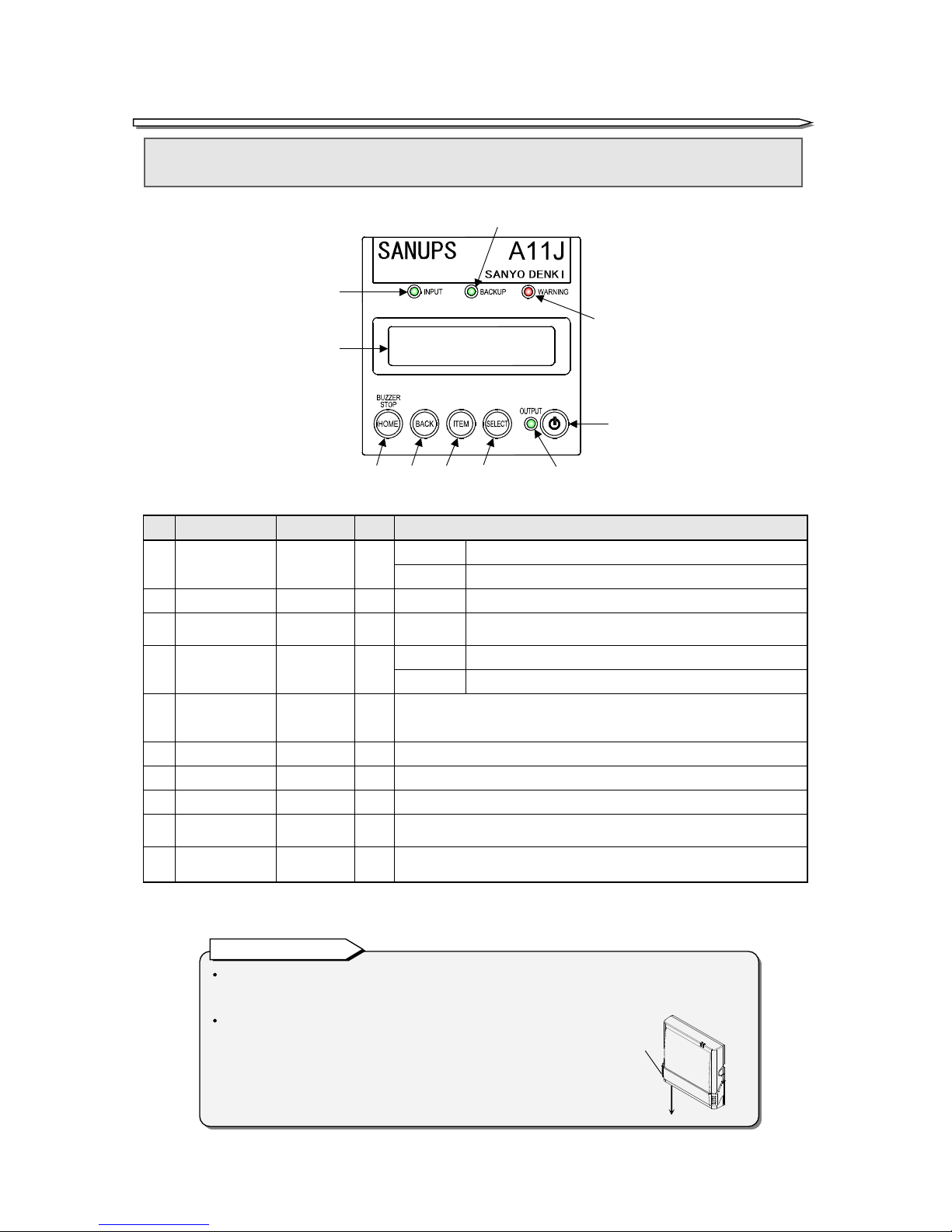
§1. Identifying LCD Panel............................................................................................................... 1
§1.1 Names of LCD Panel Parts.............................................................................................. 1
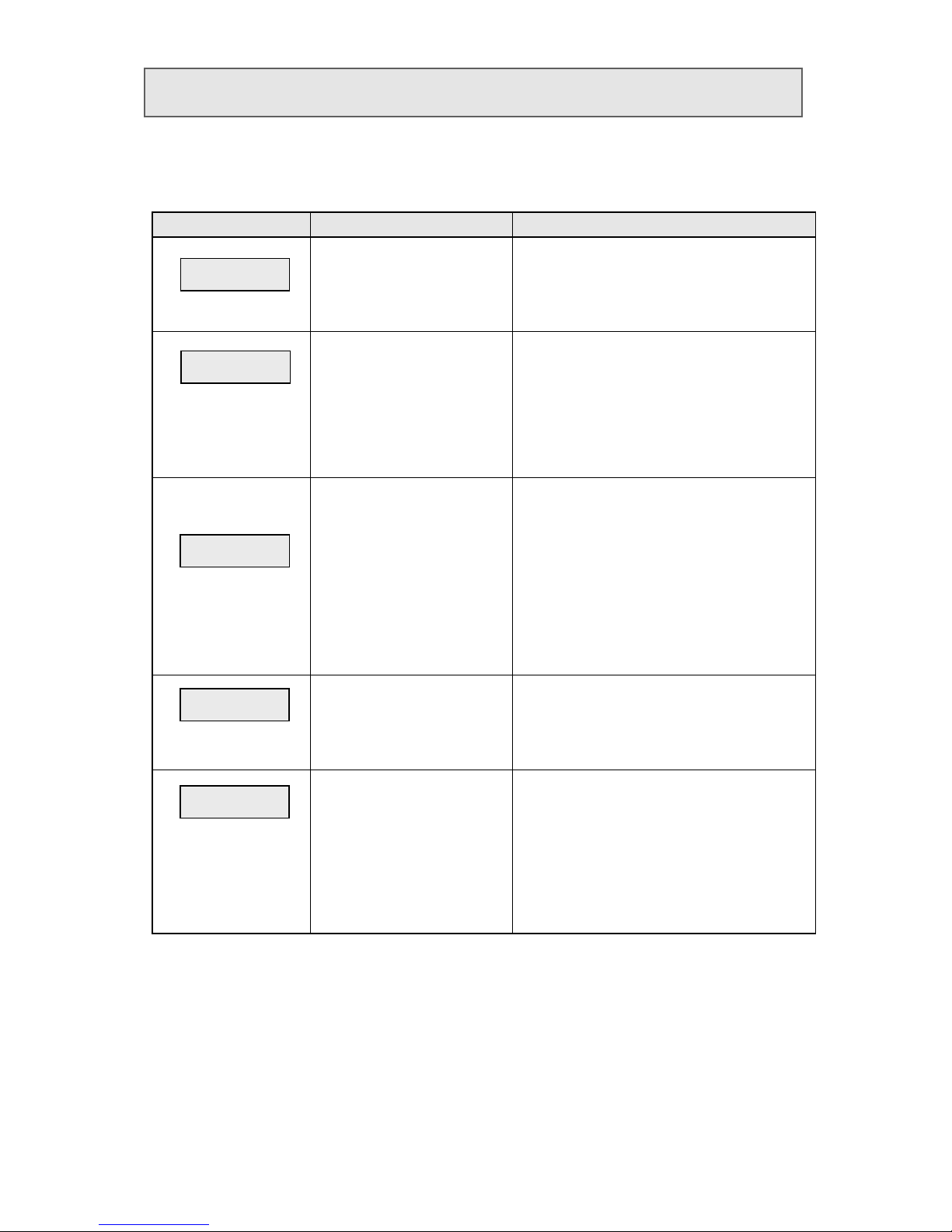
§1.2 Functions of Home Menus............................................................................................... 2
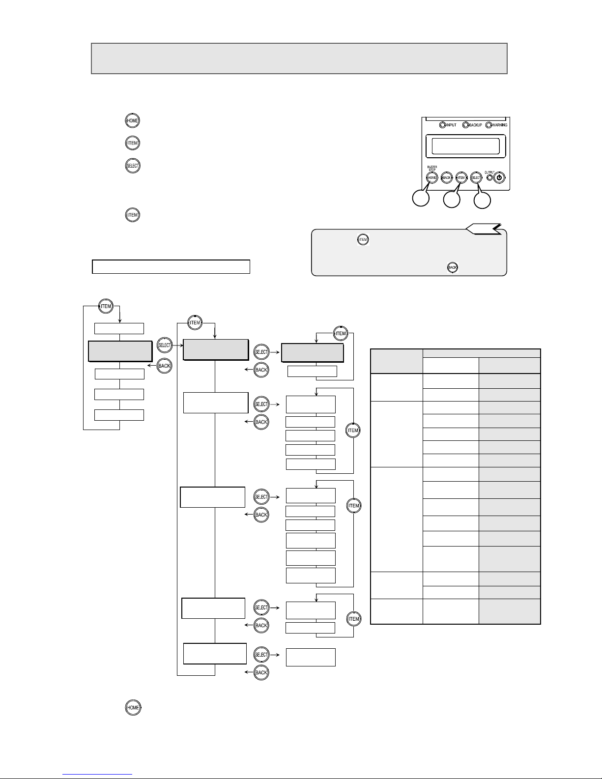
§1.3 How to Operate LCD Panel ............................................................................................. 3
§2. Viewing UPS Information ......................................................................................................... 4
§2.1 Viewing UPS Operation Status ....................................................................................... 4
§2.2 Viewing UPS Measurements ........................................................................................... 5
§3. Setting UPS ............................................................................................................................... 6
§3.1 Setting Voltage................................................................................................................. 8
§3.2 Setting Synchronous Frequency Tracking Range ........................................................... 9
§3.3 Setting Frequency........................................................................................................... 10
§3.4 Setting Voltage for Measurement Display ...................................................................... 11
§3.5 Setting PC Interface ....................................................................................................... 12
§3.6 Setting Baud Rate........................................................................................................... 13
§3.7 Setting UPS Operation Upon Power Recovery............................................................... 14
§3.8 Setting Buzzer Condition............................................................................................... 15
§3.9 Setting UPS Shutdown Operation................................................................................. 16
§3.10 Setting Overload Recovery Operation ......................................................................... 17
§3.11 Setting UPS Operation at OFF............................................................................ 18
§3.12 Setting Low Battery Voltage Warning Timing ............................................................ 19
§3.13 Setting Battery Test Time ........................................................................................... 20
§3.14 Setting Battery Test Schedule ..................................................................................... 21
§3.15 Setting Backup Time During Power Outage............................................................... 22
§3.16 Setting RING Signal.................................................................................................... 23
§3.17 Setting Adjustment for Output Voltage....................................................................... 24
§3.18 Setting Clock................................................................................................................ 25
§3.19 Setting Number of UPS Units in Parallel Connection................................................ 26
§3.20 Setting Operation System............................................................................................ 27
§3.21 Setting Input Phase..................................................................................................... 28
§3.22 Resetting Values of Settings ........................................................................................ 29
§3.23 Restarting UPS............................................................................................................ 30
§4. Operating UPS.......................................................................................................................... 31
§4.1 Running Battery Test ..................................................................................................... 32
§4.2 Reading Battery Test Result........................................................................................... 34
§4.3 Starting or Stopping UPS............................................................................................... 35
§4.4 Switching to Bypass Operation ...................................................................................... 36
§5. Maintenance Menu (For Service Technician)........................................................................... 37
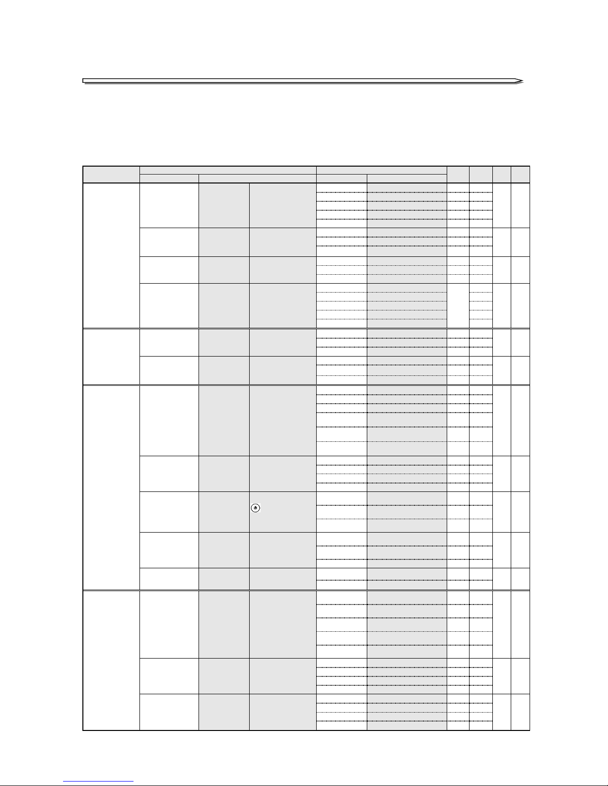
§6. Menu List.................................................................................................................................. 38
§7. Status Description .................................................................................................................... 41
§8. Notes on UPS Measurements Information .............................................................................. 42

1
About indication in LED illustration
LEDs are indicated in the form of “Green
INPUT
”, “Red
WARNING
”, etc.
About LCD panel cover operation
When using the ON/OFF button or keys:
Slide down the cover.
After the operation, return the cover to its original position.
This will prevent accidental operation.
§1. Identifying LCD Panel
§1
1.
.1
1
N
Na
am
me
es
s
o
of
f
L
LC
CD
D
P
Pa
an
ne
el
l
P
Pa
ar
rt
ts
s
No. Name Label Color Function
①
Input LED
INPUT
Green Lights When input power is normal
Blinks When input power is abnormal
②
Backup LED
BACKUP
Green Lights When the battery is operating
③
Warning LED
WARNING
Red Lights Caution/warning, malfunction, or end of battery
discharge
④
Output LED
OUTPUT
Green Lights When supplying power by inverter operation
Blinks When supplying power by bypass operation
⑤
LCD screen
- -
Displays UPS status information, measurement values,
maintenance support information, various setting values,
operation, etc.
⑥
ON/OFF button
- -
Starts and stops inverter operation
⑦
SELECT key
SELECT -
Select and accept LCD display item or content
⑧
ITEM key
ITEM -
Switches LCD display item or content
⑨
BACK key
BACK -
Cancel the selection and returns to previous LCD display (menu)
level
⑩
HOME Key
BUZZER STOP
HOME -
Return the LCD display (menu) level to the home menu
When the buzzer is sounding, stops the buzzer
A
bout LCD panel
UNINTERRUPTIBLE POWER SUPPLY
①
④
⑤
⑩⑨⑧ ⑦
②
③
⑥
Cover
Slide the cover.

2
§1
1.
.2
2
F
Fu
un
nc
ct
ti
io
on
ns
s
o
of
f
H
Ho
om
me
e
M
Me
en
nu
us
s
The LCD panel provides five home menus. Each home menu has its own setting groups and settings.
For details on each of the home menus and how to change settings, read the respective pages of the home
menus. §6. “Menu List” summaries all menus and settings.
Home menu
Function Description
Read page 4.
Status/state display
Displays UPS status.
Displayed status items:
Operation mode,
Input power, output power, battery state,
Internal error, load factor etc.
Read page 5.
Measurements/measurements
display
Displays UPS measurements.
Displayed measurement items:
Input power (voltage, frequency)
Output power (voltage, current, load factor,
frequency)
Battery (voltage, charging rate, operating
duration, battery life, number of outages)
Charging power (voltage, current)
Temperature (around device, battery
temperature)
Read pages 8 to 29.
Setting/setting
Change various UPS settings.
Settings:
Input/output: voltage, frequency, display
Interface: interface, baud rate
Operation: startup condition, buzzer sound, off
operation, overload operation, output
off operation
Battery: low battery voltage warning timing,
battery test time, test schedule
Function: operating time during outage, ring
signal, output voltage adjustment
System: time, number of connected units,
operation system, input phases
Read pages 31 to 36.
Control/operation
Operate the UPS.
Operation items:
Battery test, test result display
Turn on/off UPS
Switch to bypass operation
Maintenance menu
(for service technician)
Maintenance/maintenance
Menu for service technician.
Display or change maintenance
settings.
Do not use this home menu if
you are not a service technician.
For details, refer to the
maintenance manual for service
technician.
Displayed items:
Malfunction history, operation history, battery
information,
Operating state and measurements of each unit
Settings:
Battery backup time, battery life
STATUS
MEASUREMENT
MAINTENANCE
CONTROL
SETTING

3
§1
1.
.3
3
H
Ho
ow
w
t
to
o
O
Op
pe
er
ra
at
te
e
L
LC
CD
D
P
Pa
an
ne
el
l
①
Slide down the cover, and then press
to display the LCD screen.
②
Press tochangescreen.
③
Press to accept the selected item.
④
Press to return to the home menu, and then return the cover to its original position.
STATUS
MEASUREMENT
MAINTENANCE
CONTROL
SETTING
Example: From the “
SETTING
”
screen, press .Then, from the “
SETTING
” menu, select the interface setting.
If you press while the UPS's buzzer is beeping, the buzzer stops.
If a single press fails to stop the buzzer, keep pressing repeatedly
until the buzzer stops. The menu will not appear on the LCD screen
if you press while the buzzer is beeping.
If you do not operate the LCD screen for over 10 minutes, the panel
light goes off. In about 30 seconds later, the UPS mode and
input/output power measurement information appears randomly as
screen saver. Pressing any key displays the “
STATUS
”
of home menu
.
The actual text that appears on the LCD screen may be different
from the text and position described in the operating manual.
STATUS
Note
SETTING
SET OPERATION
Press to
return to
previous level.
Press to
move to next
level.
SETTING
SET IN/OUT
SETTING
SET I/F
SETTING
SET BATTERY
SETTING
SET FUNCTION
SETTING
SET SYSTEM
SETTING
SET DEFAULT
Pressing
repeatedly cycles
through home
menus.
SET I/F
Interface
Press to
return to
previous level.
Press to
move to next
level.
Pressing
repeatedly cycles
through settings.
The menu structure is shown below and contains several levels.
Press to move to the next level or press to return to the previous level.
Each level has several items. Pressing repeatedly cycles through the items.
When an item appears on the screen, pressing accepts the item and then
moves to the next level. The number of levels and items are different depending on
the menu, but the procedure is the same.
Repeat steps
②
and
③
to
display or set an item.
Pressing
repeatedly cycles
through items.
SET I/F
Baud Rate
Home menus
(1st level)
Group
(2nd level)
Item
(3rd level)
For details on menu contents and screen display, read their respective pages.

4
§2
2.
.
V
Vi
ie
ew
wi
in
ng
g
U
UP
PS
S
I
In
nf
fo
or
rm
ma
at
ti
io
on
n
§2
2.
.1
1
V
Vi
ie
ew
wi
in
ng
g
U
UP
PS
S
O
Op
pe
er
ra
at
ti
io
on
n
S
St
ta
at
tu
us
s
You can view the current operation status of the UPS system.
①
Press to display the LCD screen.
②
Make sure “
STATUS
”
appears on the screen.
③
Press to display the UPS status.
According to the state of the UPS, the LCD screen displays its UPS mode in the upper line and its status in the lower line.
For details on the displayed status and how to handle it, see §7. "Status Description".
UPS mode (upper line) Status (lower line)
Display Description Display Description Display Description
STANDBY
ONLINE
BYPASS
BATTERY
BATT TEST
SYS FAILURE
Standby
Online
During bypass operation
During battery operation.
During battery testing
During system malfunction
Output Not Sync
Asynchronous operation
Batt Life End
End of battery life
Input Freq Err
Input frequency error
Batt Life Warn
Battery life end warning
Input Vol Hi
High input voltage
Batt Vol Error
Battery voltage error
Input Vol Low
Low input voltage
Batt Vol End
End of battery discharge
Input Error
Input error
Batt Vol Low
Low battery voltage
INV Vol Hi
High inverter voltage
(serious malfunction)
CHG Error
Charger error
(serious malfunction)
INV Vol Low
Low inverter voltage
(serious malfunction)
CONV Error
Converter error
(serious malfunction)
INV Vol Error
Inverter voltage detection
circuit error
(serious malfunction)
BF Circuit Error
Back feed prevention circuit
error
(serious malfunction)
Output Stop (HV)
Bypass output stopped
(excessive voltage)
FIN Temp Error
Fin temperature error
(serious malfunction)
Over Load
Overload
DSP Error
Controller error
(serious malfunction)
Vo= V Fo= Hz
Output voltage, output
frequency
BUS Error
DC voltage error
(serious malfunction)
Vi= V Fi= Hz
Input voltage, input
frequency
AUX2 Error
Auxiliary power error
(minor malfunction)
LF= % CHG= %
*Load factor %, Charging
rate %
Total Unit# Err
Total number of units error
(serious malfunction)
LF= % Tim= m
*Load factor %, Charging
duration minutes
LCD Error
LCD panel error
Byp Fuse Error
Bypass fuse error
Minor Error
Minor malfunction
Bypass SW ON
Bypass switch ON
Fatal Error
Serious malfunction
Req To Restart
Restart is necessary
FT Disabled
Redundant operation not
allowed
Remote
Battery test by remote
operation in progress
Check Unit Error
Device error exists and
checking is required
Remote OFF
Operation stops due to
remote OFF
EPO ON
Operation stopping due to
EPO
④
Press to return to the home menu.
13
*1. Pressing repeatedly cycles through the displayed items.
If you miss a desired item, just keep on pressing until you see it
again.
*2. To return to the previous level, press .
*3. For details on the displayed contents, consult your supplier or
SANYO DENKI. Also, if device error or malfunction
information appears, contact your supplier or SANYO DENKI.
Tip
Status
Home menu
MEASUREMENT
MAINTENANCE
*1
SETTING
STATUS
LF= % CHG= %
- ONLINE -
****
CONTROL
FT Disabled
LF= % Tim= m
If there are multiple statuses, the lower
line automatically scrolls to display them.
Upper line: UPS mode
Lower line: Status information such as measurements,
warning, and malfunction.
2
STATUS
*2
*3
* Refer to §8 “Notes on UPS Measurements Information.”

5
§2
2.
.2
2
Viewing UPS Measurements
You can view various UPS measurements.
The displayed measurements refer to numbers about the UPS system.
①
Press to display the LCD screen.
②
Press to change the home menu to the one shown below.
③
Press to accept it.
④
In the same way, follow the figure below to make selection at each level, as follows:
”Home menu”
→
”Measurement setting”
→
”Measurements”
⑤
Press to select a measurement to view.
⑥
Press to return to the home menu.
Fin = Hz
1 23
STATUS
Measurement settings
Home menu
STATUS
CONTROL
Measurements
Example: Viewing UPS input voltage
MEASUREMENT
SETTING
*1. Pressing repeatedly cycles through the displayed
items. Therefore, if you miss a desired item, just keep
on pressing until you see it again.
*2. To return to the previous level, press .
MAINTENANCE
MEASUREMENT
INPUT
MEASUREMENT
OUTPUT
MEASUREMENT
BATTERY
MEASUREMENT
CHARGER
MEASUREMENT
TEMPERATURE
MEASUREMENT
Vin = V
Iout = A
LF = %
Watt = kW
Fout = Hz
ChgRate = %
RunTm = Min.
Ichg = A
MEASUREMENT
T-Amb =
°
C
POWER Failure
Times
BATTERY Life
Years
Backup OPE. Time
Sec.
MEASUREMENT
Vchg = V
MEASUREMENT
Vbatt = V
MEASUREMENT
Vout = V
Measurement
settings
Measurements
Measurements
displayed Description
INPUT
(input
measurements)
Vin = V
Input voltage
Fin = Hz
Input frequency
OUTPUT
(output
measurements)
Vout = V
Output voltage
Iout = A
Output current
LF = %
*
Load factor
Watt = kW
Output power
Fout = Hz
Output frequency
BATTERY
(battery
measurements)
Vbatt = V
Battery voltage
ChgRate = %
* Battery charging
rate
RunTm = Min.
* Battery retention
time
Power Failure
Times
Number of outages
Battery Life
Years
Battery life
Backup OPE. Time
Sec.
Accumulated
time on battery
operation
CHARGER
(charger
measurements)
Vchg = V
Charger voltage
Ichg = A
Charger current
TEMPERATURE
(temperature
measurements)
T-Amb =
°
C
Ambient
temperature
*1
*2
Tip
* Refer to §8 “Notes on UPS Measurements Information.”

6
§3
3.
.
S
Se
et
tt
ti
in
ng
g
U
UP
PS
S
The SETTING menu contains 7 settings groups. The “
*
” in the “Default setting” column indicates factory
defaults. Change the settings to suit your operating environment or usage. For details on how to change the
settings, read sections §3.1 to §3.22. Once you change the value of a setting, we recommend that you place a
check mark in the “Current setting” column.
List of settings
Home menu: SETTING
Settings group
Settings Values
Default
setting
Current
setting
Ref
item
Ref
page
Display Description Display Description
SET IN/OUT
(Input/Output
Setting)
Voltage
Voltage
★
Set UPS voltage.
Output voltage and
input voltage are the
same.
200V
Output voltage 200V
*
3.1 8
220V
Output voltage 220V
230V
Output voltage 230V
240V
Output voltage 240V
208V
Output voltage 208V
FREQ Range
Synchronous
frequency
tracking range
★
Set the range
(
%) at
which the output
frequency tracks the
input frequenc
y
.
1% ±
1%
3.2 9
3% ±
3%
*
5% ±
5%
Frequency
Output
frequency
★
Set output frequency.
Auto
Automatic selection
*
3.3 10
50Hz
Fixed at 50Hz
60Hz
Fixed at 60Hz
Display
Voltage current
display
Set input/output
voltage and current
for display in
measurements
display etc.
200V/200V(S)
*3 200V/200V(S)
*2
3.4 11
200V/100V
200V/100V
100V/200V
100V/200V
100V/100V
100V/100V
200V/200V
200V/200V
SET I/F
(Interface Setting)
Interface
Interface
Set interface for
using PC interface
connector.
Standalone
Standalone
3.5 12
WS
Workstation
*
Terminal
*1 Terminal
Baud Rate
Baud rate
Set
b
aud rate for
connection with PC,
LAN card, or
workstation.
9600
9600bps
*
3.6 13
4800
4800bps
2400
2400bps
SET OPERATION
(Operation
Setting)
Start Condition
Specify power
recovery
operation.
Set UPS operation to
perform when utility
power recovers, after
UPS stops due to end
of battery discharge
in power outage.
Auto
Auto start
*
3.7 14
Any Condition
Always start
STOP
Stop
BATT>30%
Start when charging rate
reaches 30%
BATT>50%
Start when charging rate
reaches 50%
BATT>80%
Start when charging rate
reaches 80%
BUZZER
Buzzer sound Set when the buzzer
should beep.
ALL
All
*
3.8 15
Group #1
Group 1
Group #2
Group 2
SILENT
Stop
OFF Operation
Operation of
OFF
Set how to turn off
on the operation
panel of the main
unit to stop the UPS.
1 Sec.
Turn off when pressed for 1
second
*
3.9 16
3 Sec.
Turn off when pressed for 3
seconds
Unique
Turn off by special
operation
OVERLOAD
Operation for
overload
Set what to do after
power supply
switches to bypass
due to overload.
Auto Ret BYP
A
utomatic recovery from
bypass
3.10 17
Stay on BYP
Bypass power supply during
overload
*
Output OFF *1
Stop output
Output @OFF
Power supply
during OFF
★
Set output's power
supply state when
UPS stops.
OFF
Stop output
*
3.11 18
BYPASS
Bypass power supply
SET BATTERY
(Battery Setting)
BATLV Timing
BATLV timing
Set when to issue low
battery voltage
warning.
Voltage
When battery voltage
threshold detected
*
3.12 19
2 Min.
When 2 minutes left in
battery capacity
3 Min.
When 3 minutes left in
battery capacity
5 Min.
When 5 minutes left in
battery capacity
10 Min.
When 10 minutes left in
battery capacity
BATT TST Length
Battery test
time
Set duration to
perform battery test.
2 Min
Run for 2 minutes
*
3.13 20
5 Min.,
Run for 5 minutes
10 Min.
Run for 10 minutes
20 Min.
Run for 20 minutes
BATT TST Period
Battery test
schedule
Set interval (number
of days) to run
battery test
automatically.
180 days
Automatically every 180 days
*
3.14 21
90 days
Automatically every 90 days
30 days
Automatically every 30 days
None
No automatic testing

7
Settings group
Settings Values
Default
setting
Current
setting
Ref
item
Ref
page
Display Description Display Description
SET FUNCTION
(Function Setting)
RUN TIM @PF
Operating
period during
outage
Set the time from
when UPS starts
backup to when it
stops output.
BATT END
Until end of battery
discharge
*
3.15 22
10 Sec.
Stop output after 10
seconds
30 Sec.
Stop output after 30
seconds
1 Min.
Stop output after 1
minute
3 Min.
Stop output after 3
minutes
5 Min.
Stop output after 5
minutes
10 Min.
Stop output after 10
minutes
RING Output
RING operation
Set whether to output
RING signal during
UPS startup.
Output
Output
3.16 23
None
Do not output
*
Out Vol Adj.
Output voltage
adjustment
Set value adjustment
for rated voltage set
in 3.1.
Each increment of
adjustment is about
1V
-3
Minus 3 increments
3.17 24
-2
Minus 2 increments
-1
Minus 1 increment
0
No adjustment
*
+1
Plus 1 increment
+2
Plus 2 increments
+3
Plus 3 increments
SET SYSTEM
(System Setting)
DATE/TIME
Date/Time Set date and time for
UPS.
DATE YY/MM/DD
TIME HH:MM:SS
Date YY/MM/DD
Time HH/MM/SS
3.18 25
ChA Total Unit#
Number of
units in ChA
system parallel
connection
Set the number of
UPS units connected
in the UPS system.
1
*3
1 unit
*2
3.19 26
2
2 units
3
3 units
4
4 units
5
5 units
6
6 units
7
7 units
8
8 units
ChB Total Unit#
Number of
units in ChB
system parallel
connection
Do not change this
setting .
1
Do not change this
setting.
*
3.19 26
2
3
4
5
6
7
8
Redundancy
UPS operation
system
Redundant operation,
or single / parallel
operation
N+1
Redundant operation
3.20 27
None
Single /
parallel operation
*
INPUT Phases
Input phase
★
Set number of input
phases of UPS
Single
Single phase, 2 wires
*
3.21 28
3Ph/4W *1
3 phases, 4 wires
SET DEFAULT
(Initialization)
SET DEFAULT
Reset to factory defaults
- -
-
3.22 29
Do not set values marked with “*1”.
The default value of “*2” is different depending on the UPS model. If you reset the value using “
SET DEFAULT
”,
the value will not be set to its default but the one indicated by “*3”.
For settings marked with “
★
”, after you change their values, the values will not take effect until you restart
the UPS. Therefore, after changing the values, read §3.23 “Restarting UPS” and then start the UPS again.
For details on UPS operation, refer to the
A11J Instruction Manual
. Before stopping the UPS, always be sure
to stop the load device first.
Note

8
§3
3.
.1
1
S
Se
et
tt
ti
in
ng
g
V
Vo
ol
lt
ta
ag
ge
e
This section describes how to set the UPS voltage.
①
Press to display the LCD screen.
②
Press to change the home menu to the one shown below.
③
Press to accept it.
④
In the same way, follow the figure below to make selection at each level, as follows:
“Home menu” “Settings group” “Settings” “Values”
⑤
Use to switch values, and then press to select a desired value. When the confirmation screen appears, press
again to accept the value.
⑥
Press to return to the home menu.
*1. Pressing repeatedly cycles through the displayed
items. If you miss a desired item, just keep on pressing
until you see it again.
*2. To return to the previous level, press .
*3. When you switch to the values screen, the value shown is
the current value, which is indicated by “
>>
”.
*4. When a value has been changed and accepted, it is
indicated by “
@>
”. After you restart the UPS, the indication
becomes “
>>
” (current value).
Settings group Settings
Home menu
STATUS
MEASUREMENT
SETTING
MAINTENANCE
CONTROL
SETTING
SET IN/OUT
SET IN/OUT
Voltage
SET I/F
SET OPERATION
SET BATTERY
SET FUNCTION
SET SYSTEM
FREQ Range
Frequency
Display
Voltage
>>200V
Value s
220V
Voltage
208V
1 23
Details on settings and values
Val ues Description
200V
Specify UPS output voltage.
Input voltage and output
voltage are the same.
Check the input voltage and
then select the same voltage.
220V
230V
240V
208V
If W1 type or W2 type is used, do not change
the value. If you changed the value by mistake,
use the procedure above to change it to 200V,
and then restart the UPS.
[SELECT] = OK
[BACK] = Cancel
230V
240V
Default
STATUS
Voltage
@> 208V
Example: Change output voltage to “
208V
”
Confirm
Accept
Tip
SET DEFAULT
After you change a setting, read §3.23 “Restarting UPS” and
then start the UPS again; otherwise, the change will not
take effect. To stop the UPS, alawys stop the load device.
If the UPS status display is “
Req. to restart
”:
Values for settings are changed but you have not restarted
the UPS. See §3.23 “Restarting UPS” and then restart the
UPS.
Note
*1
*2
*3
*4

9
§3
3.
.2
2
S
Se
et
tt
ti
in
ng
g
S
Sy
yn
nc
ch
hr
ro
on
no
ou
us
s
F
Fr
re
eq
qu
ue
en
nc
cy
y
T
Tr
ra
ac
ck
ki
in
ng
g
R
Ra
an
ng
ge
e
This section describes how to specify a tracking range to synchronize the output frequency with the input
frequency.
①
Press to display the LCD screen.
②
Press to change the home menu to the one shown below.
③
Press to accept it.
④
In the same way, follow the figure below to make selection at each level, as follows:
“Home menu” “Settings group” “Settings” “Values”
⑤
Use to switch values, and then press to select a desired value. When the confirmation screen appears, press
again to accept the value.
⑥
to return to the home menu.
Settings group Settings
Home menu
STATUS
MEASUREMENT
SETTING
MAINTENANCE
CONTROL
SETTING
SET IN/OUT
SET IN/OUT
Voltage
SET I/F
SET OPERATION
SET BATTERY
SET FUNCTION
SET SYSTEM
Frequency
Display
FREQ Range
>> 3%
V
alues
1%
FREQ Range
5%
1 23
Details on settings and values
Val ues Description
1 % ±
1% of input frequency
3 % ±
3% of input frequency
5 % ±
5% of input frequency
A smaller value provides better
precision. However, if the input
frequency is unstable, the UPS tends to
switch to the asynchronous operation.
To connect to output of the engine
power generator, select 5%.
During the asynchronous operation, if
the UPS switches to the bypass
operation, this will be instant cutoff
switching.
The inverter will not operate unless the
input frequency is within the specified
tracking range (±1%, ±3%, or ±5%) of
the frequency setting in §3.3 (“50Hz”,
“60Hz”, or “Auto”).
[SELECT] = OK
[BACK] = Cancel
Default
STATUS
SET IN/OUT
FREQ Range
FREQ Range
@> 5%
Confirm
A
ccept
Example: Change the synchronous frequency tracking range to “
5%
”
SET DEFAULT
*1
*2
*3
*4
*1. Pressing repeatedly cycles through the displayed
items. If you miss a desired item, just keep on pressing
until you see it again.
*2. To return to the previous level, press .
*3. When you switch to the values screen, the value shown is
the current value, which is indicated by “
>>
”.
*4. When a value has been changed and accepted, it is
indicated by “
@>
”. After you restart the UPS, the indication
becomes “
>>
” (current value).
Tip
After you change a setting, read §3.23 “Restarting UPS” and
then start the UPS again; otherwise, the change will not take
effect. To stop the UPS, alawys stop the load device.
If the UPS status display is “
Req. to restart
”:
Values for settings are changed but you have not restarted the
UPS. See §3.23 “Restarting UPS” and then restart the UPS.
Note

10
§3
3.
.3
3
S
Se
et
tt
ti
in
ng
g
F
Fr
re
eq
qu
ue
en
nc
cy
y
The frequency has been set to “
Auto
” when the UPS is shipped from the factory. Do not change the value, except
when using UPS in a special power supply environment. If you changed the value accidentally, use the
procedure below to change it to “
Auto
”.
①
Press to display the LCD screen.
②
Press to change the home menu to the one shown below.
③
Press to accept it.
④
In the same way, follow the figure below to make selection at each level, as follows:
“Home menu”
→
“Settings group”
→
“Settings”
→
“Values”
⑤
Use to switch values, and then press to select a desired value. When the confirmation screen appears, press
again to accept the value.
⑥
Press to return to the home menu.
After you change a setting, read §3.23 “Restarting UPS” and
then start the UPS again; otherwise, the change will not take
effect. To stop the UPS, alawys stop the load device.
If the UPS status display is “
Req. to restart
”:
Values for settings are changed but you have not restarted the
UPS. See §3.23 “Restarting UPS” and then restart the UPS.
Settings group Settings
Home menu
STATUS
MEASUREMENT
SETTING
MAINTENANCE
CONTROL
SETTING
SET IN/OUT
SET IN/OUT
Voltage
SET I/F
SET OPERATION
SET BATTERY
SET FUNCTION
SET SYSTEM
FREQ Range
Display
Frequency
>> 60Hz
Value s
50Hz
Frequency
Auto
1 23
[SELECT] = OK
[BACK] = Cancel
STATUS
SET IN/OUT
Frequency
FREQ Range
@> Auto
Confirm
A
ccept
Example: Set frequency to “
Auto
”
SET DEFAULT
*1. Pressing repeatedly cycles through the displayed
items. If you miss a desired item, just keep on pressing
until you see it again.
*2. To return to the previous level, press .
*3. When you switch to the values screen, the value shown
is the current value, which is indicated by “
>>
”.
*4. When a value has been changed and accepted, it is
indicated by “
@>
”. After you restart the UPS, the
indication becomes “
>>
” (current value).
Tip
*4
*3
*2
*1
Note
Details on settings and values
Value Description
Auto
Set the output
frequency to match
the input frequency
automatically.
If “
Auto
” is selected, when the frequency exceeds the tracking range set in §3.2
“Setting Synchronous Frequency Tracking Range”, the UPS switches to the
asynchronous operation. If frequency exceeds ±8% of the specified frequency, the
UPS switches to the battery operation.
50Hz
Set the output
frequency to 50Hz.
If “
50Hz
” or “
60Hz
” is selected, the output frequency does not
synchronize with the input frequency but the specified
frequency is output. In this case, the input frequency's
acceptable range is 40Hz to 120Hz. If this range is exceeded,
the UPS switches to the battery operation. During UPS
startup or recovery from battery operation, the operation
same as that specified in the “
Auto
” setting is used.
Contact SANYO
DENKI beforehand if
you need to change
the frequency setting
to “
50Hz
” or “
60Hz
”.
60Hz
Set the output
frequency to 60Hz.
The synchronous frequency tracking range (
±1%
,
±3%
, or
±5%
) is set in §3.2. Regardless of the frequency setting here
(“
50Hz
”, “
60Hz
”, or “
Auto
”), the inverter will not start up unless the input frequency is within the specified tracking
range.
When “
50Hz
” or “
60Hz
” is set, the battery test described in §4.1 “Running Battery Test” is not available. Also, even if you
set the battery test schedule to perform battery test automatically in §3.14 “Setting Battery Test Schedule”, the
battery test will not be performed.
When “
50Hz
” or “
60Hz
” is set, if the UPS switches to the bypass operation by manual switching operation or an
overload, it will be instant cutoff switching.
Default

11
§3
3.
.4
4
S
Se
et
tt
ti
in
ng
g
V
Vo
ol
lt
ta
ag
ge
e
f
fo
or
r
M
Me
ea
as
su
ur
re
em
me
en
nt
t
D
Di
is
sp
pl
la
ay
y
This section describes how to specify an input/output voltage for measurement display.
If you have connected the UPS to a collector unit, change this setting according to the specifications of the
collector unit.
①
Press to display the LCD screen.
②
Press to change the home menu to the one shown below.
③
Press to accept it.
④
In the same way, follow the figure below to make selection at each level, as follows:
“Home menu”
→
“Settings group”
→
“Settings”
→
“Values”
⑤
Use to switch values, and then press to select a desired value. When the confirmation screen appears, press
again to accept the value.
⑥
Press to return to the home menu.
*1. Pressing repeatedly cycles through the
displayed items. If you miss a desired item,
just keep on pressing until you see it again.
*2. To return to the previous level, press .
*3. When you switch to the values screen, the
value shown is the current value, which is
indicated by “
>>
”.
*4. When a value has been changed and accepted,
it is indicated by “
>>
” (current value).
Settings group
Settings
Home menu
STATUS
MEASUREMENT
SETTING
MAINTENANCE
CONTROL
SETTING
SET IN/OUT
SET IN/OUT
Voltage
SET I/F
SET OPERATION
SET BATTERY
SET FUNCTION
SET SYSTEM
FREQ Range
Display
>> 200V/200V(S)
V
alues
100V/100V
Display
200V/100V
1 23
Details on settings and values
Value Description
200V/200V(S)
If rated input voltage and output
voltage are both 200V type
This is the default setting for S2 type or single-type.
If the voltage is set to 200V, 220V, 230V, 240V, or 208V, this is
the value used. If S2 type or single-operation type is used,
do not change this setting.
200V/100V
If rated input voltage is 200V and
output voltage is 100V For W1 or W2 type, the default is different depending on the
UPS model.
If the PDU unit's terminal block is modified, change the value
according to the specification.
For details on terminal block settings and values, refer to the
A11J Instruction Manual
.
100V/200V
If rated input voltage is 100V and
output voltage is 200V
100V/100V
If rated input voltage and output
voltage are both 100V
200V/200V
If rated input voltage and output
voltage are both 200V
These are the values of voltage and current that appear on the LCD screen when UPS measurements are displayed.
If you change the voltage, the current is also changed.
If the value is different from the UPS rated voltage, the measurements will not be displayed correctly.
If you have performed the operation described in §3.22 “Resetting Values of Settings”, the value becomes “
200V/200V(S
)
”.
[SELECT] = OK
[
BACK] = Cancel
STATUS
SET IN/OUT
Display
Display
>> 200V/100V
Confirm
A
ccept
Example: Set display voltage to “
200V/100V
”
Frequency
100V/200V
SET DEFAULT
200V/200V
Tip
*1
*2
*3
*4

12
§3
3.
.5
5
S
Se
et
tt
ti
in
ng
g
P
PC
C
I
In
nt
te
er
rf
fa
ac
ce
e
This section describes how to specify an interface method when a PC interface connector is used. For details on
PC interface connector, refer to §5.4 “External Interface” in the
A11J Instruction Manual
.
①
Press to display the LCD screen.
②
Press to change the home menu to the one shown below.
③
Press to accept it.
④
In the same way, follow the figure below to make selection at each level, as follows:
“Home menu”
→
“Settings group”
→
“Settings”
→
“Values”
⑤
Use to switch values, and then press to select a desired value. When the confirmation screen appears, press
again to accept the value.
⑥
Press to return to the home menu.
Settings group Settings
Home menu
STATUS
MEASUREMENT
SETTING
MAINTENANCE
CONTROL
SETTING
SET I/F
SET I/F
Interface
SET OPERATION
SET BATTERY
SET FUNCTION
SET SYSTEM
Baud Rate
Interface
>> WS
Value s
Terminal
Interface
Standalone
1 23
Details on settings and values
Val ue Description
Standalone
(Standalone)
Select this value for the following cases.
* Standard UPS service of OS
* UPS remote ON/OFF using remote
switch
WS
(Workstation)
Select this value for the following cases.
* Power management software
* LAN interface card
* Computer one-touch shutdown using
remote switch
Terminal
(Terminal)
Do not use this value.
[SELECT] = OK
[BACK] = Cancel
Default
STATUS
Interface
>> Standalone
Example: Set interface to “
Standalone
”
Confirm
A
ccept
SETTING
SET IN/OUT
SET DEFAULT
*1. Pressing repeatedly cycles through the displayed
items. If you miss a desired item, just keep on pressing
until you see it again.
*2. To return to the previous level, press .
*3. When you switch to the values screen, the value shown
is the current value, which is indicated by “
>>
”.
*4. When a value has been changed and accepted, it is
indicated by “
>>
“ (current value).
Tip
*1
*2
*3
*4

13
§3
3.
.6
6
S
Se
et
tt
ti
in
ng
g
B
Ba
au
ud
d
R
Ra
at
te
e
This section describes how to specify a baud rate for connection to a workstation, PC, or LAN interface card.
①
Press to display the LCD screen.
②
Press to change the home menu to the one shown below.
③
Press to accept it.
④
In the same way, follow the figure below to make selection at each level, as follows:
“Home menu”
→
“Settings group”
→
“Settings”
→
“Values”
⑤
Use to switch values, and then press to select a desired value. When the confirmation screen appears, press
again to accept the value.
⑥
Press to return to the home menu.
Settings group
Settings
Home menu
STATUS
MEASUREMENT
SETTING
MAINTENANCE
CONTROL
SETTING
SET I/F
SET I/F
Baud Rate
SET OPERATION
SET BATTERY
SET FUNCTION
SET SYSTEM
Baud Rate
>> 9600
Value s
2400
Baud Rate
4800
1 23
Details on settings and values
Val ue Description
9600
Baud rate 9600 bps
4800
Baud rate 4800 bps
2400
Baud rate 2400 bps
When a LAN interface card is used, set the baud
rate to 9600 bps.
[SELECT] = OK
[BACK] = Cancel
Default
STATUS
Example: Set baud rate to “
4800
”
Confirm
Accept
SETTING
SET IN/OUT
SET I/F
Interface
Baud Rate
>> 4800
SET DEFAULT
*1. Pressing repeatedly cycles through the displayed
items. If you miss a desired item, just keep on pressing
until you see it again.
*2. To return to the previous level, press .
*3. When you switch to the values screen, the value shown
is the current value, which is indicated by “
>>
”.
*4. When a value has been changed and accepted, it is
indicated by “
>>
“ (current value).
Tip
*4
*3
*2
*1

14
§3
3.
.7
7
S
Se
et
tt
ti
in
ng
g
U
UP
PS
S
O
Op
pe
er
ra
at
ti
io
on
n
U
Up
po
on
n
P
Po
ow
we
er
r
R
Re
ec
co
ov
ve
er
ry
y
This section describes how to specify an operation to use in utility power recovery after the UPS is stopped by
end of battery discharge during power outage.
①
Press to display the LCD screen.
②
Press to change the home menu to the one shown below.
③
Press to accept it.
④
In the same way, follow the figure below to make selection at each level, as follows:
“Home menu” “Settings group” “Settings” “Values”
⑤
Use to switch values, and then press to select a desired value. When the confirmation screen appears, press
again to accept the value.
⑥
Press to return to the home menu.
Settings group
Settings
Home menu
STATUS
MEASUREMENT
SETTING
MAINTENANCE
CONTROL
SET OPERATION
Start Condition
SET I/F
SET BATTERY
SET FUNCTION
SET SYSTEM
BUZZER
Start Condition
>>Auto
V
alues
Any Condition
1 23
Details on settings and values
Val ue Description
Auto
Automatic
The UPS restarts automatically when the utility power recovers.
Any
Condition
Always
start
The UPS always starts automatically when input power is received, regardless of
whether it is power recovery after outage or input power is received at initial startup.
STOP
Stop The UPS stays off even when the utility power recovers. However, if
“
BYPASS
”
is
selected in §3.11, bypass power is used.
BATT > 30%
More
than 30%
The UPS restarts automatically when battery charge reaches 30% if the utility power
recovers.
BATT > 50%
More
than 50%
The UPS restarts automatically when battery charge reaches 50% if the utility power
recovers.
BATT > 80%
More
than 80%
The UPS restarts automatically when battery charge reaches 80% if the utility power
recovers.
When power management software is used, the UPS starts at the charging rate specified by the power management
software. Even if you set this item by the procedures above, the value cannot be enabled. In such a case, when you
display the value by the procedures above, the value of power management software appears as follows.
Example:
When you press , this value disappears. Press to go back once, and then press , it is displayed again.
[SELECT] = OK
[BACK] = Cancel
Default
STATUS
Example: Specify “
STOP
” as the operation for power recovery.
Confirm
A
ccept
SETTING
SET IN/OUT
SETTING
SET OPERATION
OFF Operation
OVER Load
Output @OFF
Start Condition
STOP
BATT > 30%
BATT > 50%
BATT > 80%
Start Condition
>>STOP
SET DEFAULT
*1
*2
*3
*4
*1. Pressing repeatedly cycles through the
displayed items. If you miss a desired item,
just keep on pressing until you see it again.
*2. To return to the previous level, press .
*3. When you switch to the values screen, the
value shown is the current value, which is
indicated by “
>>
”.
*4. When a value has been changed and accepted,
it is indicated by “
>>
” (current value).
Tip
Start Condition
BATT > 5%(Val)
“(Val)” at the end of the value indicates the value set by power management software.

15
§3
3.
.8
8
S
Se
et
tt
ti
in
ng
g
B
Bu
uz
zz
ze
er
r
C
Co
on
nd
di
it
ti
io
on
n
This section describes how to specify a condition to sound the buzzer.
①
Press to display the LCD screen.
②
Press to change the home menu to the one shown below.
③
Press to accept it.
④
In the same way, follow the figure below to make selection at each level, as follows:
“Home menu” “Settings group” “Settings” “Values”
⑤
Use to switch values, and then press to select a desired value. When the confirmation screen appears, press
again to accept the value.
⑥
Press to return to the home menu.
1 23
STATUS
Settings group
Settings
Home menu
STATUS
MEASUREMENT
SETTING
MAINTENANCE
CONTROL
SET I/F
SET BATTERY
SET FUNCTION
SET SYSTEM
BUZZER
>> ALL
V
alues
Group #1
[SELECT] = OK
[BACK] = Cancel
Example: Specify “
Group #2
” as a condition to sound the buzzer
Confirm
A
ccept
SETTING
SET IN/OUT
SETTING
SET OPERATION
OFF Operation
OVER Load
Output @OFF
BUZZER
Group #2
SILENT
Details on settings and values
Value Description
ALL
All states
Buzzer beeps in following cases:
Battery operation, battery testing, battery voltage error, low battery voltage,
overload (bypass operation), battery life end warning, battery life end, serious
malfunction, minor malfunction, end of discharge, request for buzzer from power
management software. (Button operation sounds are also enabled.)
Group #1
Group 1
Buzzer beeps in following cases:
Low battery voltage, battery life end warning, battery life end, serious
malfunction, minor malfunction, end of discharge, request for buzzer from power
management software. (Button operation sounds are also enabled.)
Group #2
Group 2
Buzzer beeps in following cases:
Serious malfunction, request for buzzer from power management software.
(Button operation sounds are also enabled.)
SILENT
Stop Only the button operation sounds are enabled.
Default
SET OPERATION
BUZZER
SET OPERATION
Start Condition
BUZZER
>> Group #2
SET DEFAULT
*1
*2
*3
*4
*1. Pressing repeatedly cycles through the
displayed items. If you miss a desired item,
just keep on pressing until you see it again.
*2. To return to the previous level, press .
*3. When you switch to the values screen, the
value shown is the current value, which is
indicated by “
>>
”.
*4. When a value has been changed and accepted,
it is indicated by “
>>
” (current value).
Tip

16
§3
3.
.9
9
S
Se
et
tt
ti
in
ng
g
U
UP
PS
S
S
Sh
hu
ut
td
do
ow
wn
n
O
Op
pe
er
ra
at
ti
io
on
n
This section describes how to shut down the UPS using on its control panel. This setting prevents
unintended contact or accidental operation of the button to cause the UPS to stop.
On the control panel, only the “OFF operation” of is enabled, but the “ON operation” cannot be changed.
①
Press to display the LCD screen.
②
Press to change the home menu to the one shown below.
③
Press to accept it.
④
In the same way, follow the figure below to make selection at each level, as follows:
“Home menu” “Settings group” “Settings” “Values”
⑤
Use to switch values, and then press to select a desired value. When the confirmation screen appears, press
again to accept the value.
⑥
Press to return to the home menu.
1 23
STATUS
Settings group
Settings
Home menu
STATUS
MEASUREMENT
SETTING
MAINTENANCE
CONTROL
SET I/F
SET BATTERY
SET FUNCTION
SET SYSTEM
OFF Operation
>> 1 Sec.
V
alues
Unique
[SELECT] = OK
[BACK] = Cancel
Example: Shut down UPS in “
3 Sec
” (3 seconds)
Confirm
Accept
SETTING
SET IN/OUT
SETTING
SET OPERATION
BUZZER
OVER Load
Output @OFF
OFF Operation
3 Sec.
Details on settings and values
Val ue Description
1 Sec.
1 second Pressing for 1 second shuts down the UPS.
3 Sec.
3 seconds Pressing for 3 seconds shuts down the UPS.
Unique
Special
operation
Press and hold for 3 seconds and then release the button
when the buzzer starts beeping. While the buzzer is still
beeping, press for 3 seconds to shut down the UPS.
Default
SET OPERATION
Start Condition
SET OPERATION
OFF Operation
OFF Operation
>> 3 Sec.
SET DEFAULT
*1. Pressing repeatedly cycles through the
displayed items. If you miss a desired item,
just keep on pressing until you see it again.
*2. To return to the previous level, press .
*3. When you switch to the values screen, the
value shown is the current value, which is
indicated by “
>>
”.
*4. When a value has been changed and accepted,
it is indicated by “
>>
” (current value).
Tip
*1
*2
*3
*4

17
§3
3.
.1
10
0
S
Se
et
tt
ti
in
ng
g
O
Ov
ve
er
rl
lo
oa
ad
d
R
Re
ec
co
ov
ve
er
ry
y
O
Op
pe
er
ra
at
ti
io
on
n
This section describes how to specify a condition for returning to UPS power supply after switching to bypass
power because of overload.
①
Press to display the LCD screen.
②
Press to change the home menu to the one shown below.
③
Press to accept it.
④
In the same way, follow the figure below to make selection at each level, as follows:
“Home menu” “Settings group” “Settings” “Values”
⑤
Use to switch values, and then press to select a desired value. When the confirmation screen appears, press
again to accept the value.
⑥
Press to return to the home menu.
1 23
STATUS
Settings group
Settings
Home menu
STATUS
MEASUREMENT
SETTING
MAINTENANCE
CONTROL
SET I/F
SET BATTERY
SET FUNCTION
SET SYSTEM
OVER LOAD
>>Stay on BYP
V
alues
Output OFF
[SELECT] = OK
[BACK] = Cancel
Example: Set overload operation to “
Auto Ret BYP
” (Automatic return)
Confirm
A
ccept
SETTING
SET IN/OUT
SETTING
SET OPERATION
BUZZER
Output @OFF
SET OPERATION
Start Condition
SET OPERATION
OVER Load
OFF Operation
OVER LOAD
>>Auto Ret BY
SET DEFAULT
OVER LOAD
Auto Ret BYP
*4
*1
*2
*3
*1. Pressing repeatedly cycles through the
displayed items. If you miss a desired item,
just keep on pressing until you see it again.
*2. To return to the previous level, press .
*3. When you switch to the values screen, the
value shown is the current value, which is
indicated by “
>>
”.
*4. When a value has been changed and accepted,
it is indicated by “
>>
” (current value).
Tip
Details on settings and values
Value Description
Auto Ret BYP
Automatic
return
After overload causes power to switch to bypass power supply, power
switches back to UPS power supply automatically after a certain period of
time. If overload continues, power switches to bypass power supply again,
and this operation repeats.
Stay on BYP
Bypass power
supply
If overload continues, bypass power supply continues.
If overload goes away, power switches back to UPS power supply.
When power switches to bypass power supply, the power continues to switch
between UPS power supply and bypass power supply depending on the
utility power voltage value.
Output OFF
Stop output Do not use this value.
Regardless of the setting above (“
Auto Ret BYP
” or “
Stay on BYP
”), the UPS cannot switch to UPS power supply from
bypass power supply during asynchronous operation (when the input frequency is not within the specified
tracking range (±
1%
, ±
3%
, or ±
5%
) set in
§
3.2).
Under the condition below, the UPS switches to the bypass operation with instant interruption.
When “
50Hz
” or “
60Hz
” is set
in
§
3.3 “Setting frequency.”
When “
Auto
” is set
in
§
3.3 “Setting frequency” and during asynchronous operation.
Default

18
§3
3.
.1
11
1
S
Se
et
tt
ti
in
ng
g
U
UP
PS
S
O
Op
pe
er
ra
at
ti
io
on
n
a
at
t
O
OF
FF
F
This section describes how to specify UPS power supply when the button's OFF operation performed in
“UPS Shutdown” of the
A11J Instruction Manual
causes the UPS to stop (
MAIN MCCB
is ON).
①
Press to display the LCD screen.
②
Press to change the home menu to the one shown below.
③
Press to accept it.
④
In the same way, follow the figure below to make selection at each level, as follows:
“Home menu” “Settings group” “Settings” “Values”
⑤
Use to switch values, and then press to select a desired value. When the confirmation screen appears, press
again to accept the value.
⑥
Press to return to the home menu.
1 23
STATUS
Settings group
Settings
Home menu
STATUS
MEASUREMENT
SETTING
MAINTENANCE
CONTROL
SET I/F
SET BATTERY
SET FUNCTION
SET SYSTEM
Output @OFF
>>OFF
V
alues
[SELECT] = OK
[BACK] = Cancel
Example: Set power supply when button is OFF to “
BYPASS
” (bypass power supply)
Confirm
Accept
SETTING
SET IN/OUT
SETTING
SET OPERATION
BUZZER
Output @OFF
BYPASS
Details on settings and values
Val ue Description
OFF
(Stop)
When the button is OFF, the UPS stops and power
is not supplied.
BYPASS
(Bypass power supply)
When the button is OFF, power switches to bypass
power supply continues.
Default
SET OPERATION
Start Condition
SET OPERATION
Output @OFF
OFF Operation
OVER Load
Output @OFF
@>BYPASS
SET DEFAULT
After you change a setting, read §3.23 “Restarting UPS” and then start
the UPS again; otherwise, the change will not take effect.
However, if the current setting is “
BYPASS
”, setting the UPS's
MAIN MCCB
to OFF does not stop the UPS. Therefore, cut off the breaker distribution
board on the input side of the UPS, stop the UPS, and then start it again.
To stop the UPS, alawys stop the load devices first.
If the UPS status display is “
Req. to restart
”:
V
alues for settings are changed but they require restart of the UPS before
their changes take effect. Therefore, see §3.23 “Restarting UPS” and then
restart the UPS.
Note
*1. Pressing repeatedly cycles through the
displayed items. If you miss a desired item,
just keep on pressing until you see it again.
*2. To return to the previous level, press .
*3. When you switch to the values screen, the
value shown is the current value, which is
indicated by “
>>
”.
*4. When a value has been changed and accepted,
it is indicated by “
>>
” (current value).
Tip
*1
*2
*3
*4
Table of contents
Other SANUPS UPS manuals
Popular UPS manuals by other brands

CyberPower
CyberPower PR1500 user manual

Microline Surgical
Microline Surgical 200-006R Instructions for use

inform
inform Pyramid Plus OPERATING AND INSTALLATION Manual

Roline
Roline LineSecure 1000VA user manual

CyberPower
CyberPower OR1000PFCRT2U user manual

Eaton
Eaton Powerware 9355 Installation and operation manual