FE GX200 Series User manual

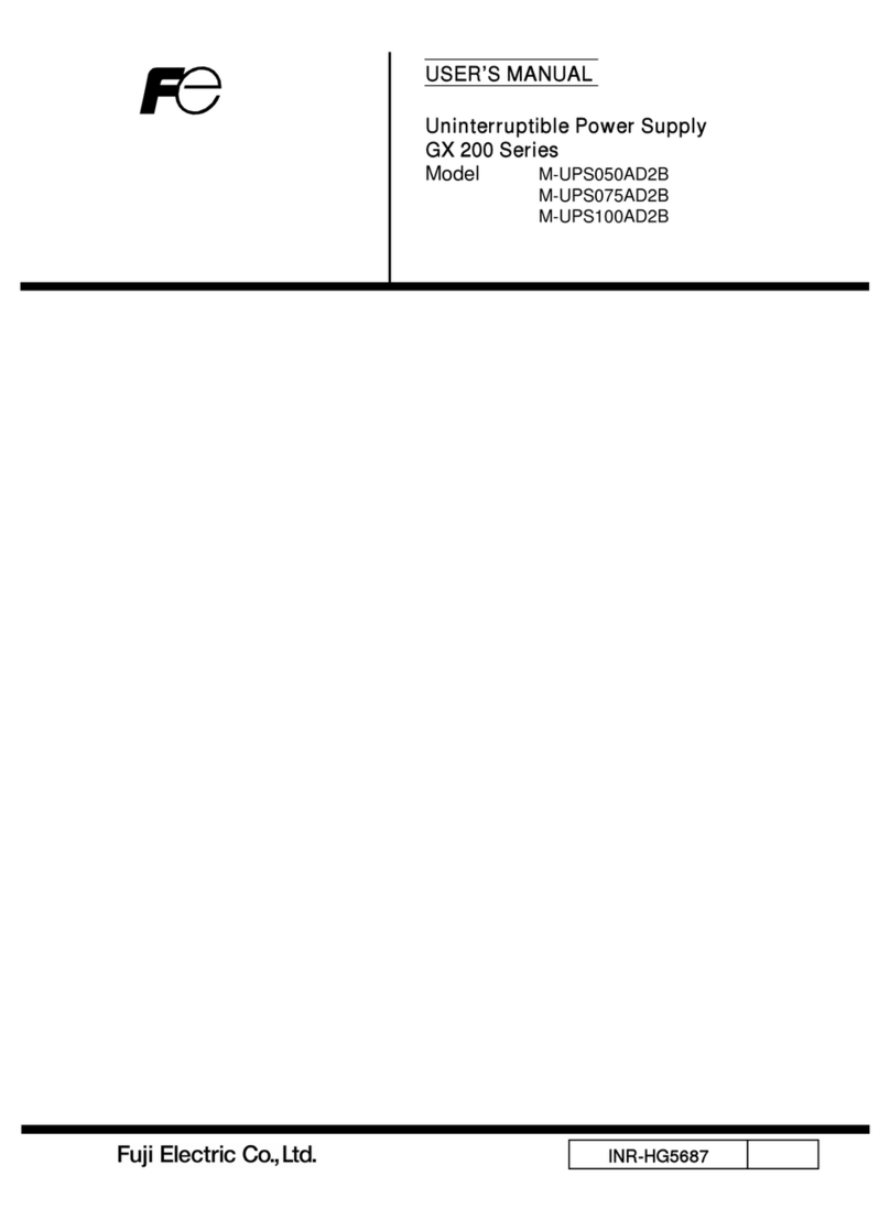
USER’S MANUAL
Uninterruptible Power Supply
GX200 Series (5kVA, 7.5kVA, 10kVA)
Model M-UPS050AD2B
M-UPS075AD2B
M-UPS100AD2B
INR-HG5687

For Safe Use
High-safety uses
This product is designed and manufactured for the general use, such as
general office use and personal use, and is not designed and manufactured for
uses (control of nuclear reactions at the nuclear facilities, aircraft flight control,
air traffic control, mass transport control, medical life support systems, and
missile launch control in weapon systems, etc.) that require a high degree of
safety, and can cause death or serious injury if the required safety is not
maintained. Do not use this product without carrying out measures to ensure
the required safety for such a use. If using this product for such a use, consult
with our sales representatives.
Prevention of radio interference
Important
This product is class A information technology device based on the standards of
the Voluntary Control Council for Interference by Information Technology
Equipment (VCCI). Use of this product in a residential area may cause radio
interference. In this case, the user may be required to take appropriate action.
Prevention of Harmonic Current Interference
M-UPS050AD2B conforms to the Guideline of harmonic restraint measures for
general-purpose UPS.
M-UPS075AD2B and M-UPS100AD2B conform to IEC61000-3-12.
All Rights Reserved, Copyright
c
○ Fuji Electric Co., Ltd. 2011
i
•Handling of this manual
This manual contains important information for safe use of the product.
Please read this instruction manual carefully before using the product to
ensure that you fully understand the product.

ii
Attention: Information in this manual is subject to change without notice.
Caution about Safety
Warning Indicates high risk of death or serious injuries when the
Important
The condition of the UPS
LED Indications
Lit
Flashing
Out
Ca ution
Following warning signs are included to prevent the user from damaging
the UPS and the connected devices.
product is not used properly.
Improper use could cause mild injuries and damage the
UPS and the connected device.
“Important” indicates caution about the use of the UPS.
Warning Signs
Symbols

iii
Caution about Saf et y
List of important warnings: Risks when UPS is not used correctly
Electric Shock Do not remove the cover of the UPS.
High voltage parts inside UPS may cause electrical shock.
"Caution" indicates that slight or moderate injury may occur
and the UPS or user's property may be damaged.
Electric
Shock Injury
Do not insert fingers or sticks into the cooling fan or the vent
hole. Doing so may cause electric shock or injury.
Electric shock Maintenance including daily inspections (battery replacement,
cooling fan replacement, etc.) should be performed by a
professional technician. Failure to do so may cause electric
shock.
This UPS requires grounding (Class D grounding or higher).
When connecting to the input power supply, connect a ground
wire to the AC input protective grounding terminal. Failure to
do so may cause electric shock.
Electric
Shock Failure
When connecting this UPS to the input power supply, connect the
active wire to the AC input 1/R and L2/S terminals and the
inactive wire to the ground terminal. Also, connect the ground
wire to the AC input protective ground terminal. Similarly, in the
connection between the output of the UPS and the connecting
device, connect the hot wire side wires to the AC output terminals
l1/U and l2/V and the ground wire to the output ground terminal.
Incorrect connection may cause noise, malfunction, failure, or
electric shock.
When maintaining the connected device, be sure to turn off
the power supply to the connected device. Turn off the
breaker on the distribution board and disconnect the AC input
terminals.
Failure to do so may cause electric shock.
Warning
Caution
Warning "Warning" indicates that death or serious injury may occur.

Caution about Safety
iv
Injury Do not step on or put an object on the UPS.
Injury
Damage
The UPS is heavy. Caution in handling the UPS.
Take out the UPS in a level and flat place. The weight of the
UPS is as follows:
•M-UPS050AD2B: 63kg (without battery: 29kg)
•M-UPS075AD2B: 127kg (without battery: 59kg)
•M-UPS100AD2B: 127kg (without battery: 59kg)
Fire
Damage
This UPS can be installed laying down.
When installing the UPS lying down, it should only be
tilted to the right side (clockwise) when viewed from the
front.
NG OK

Caution about Safety
v
Damage This UPS is not designed for medical equipment that comes in
contact with the human body.
Do not place objects affected by magnetism near the UPS.
Have the voltage set within the range of the input connected device.
Failure to do so may damage the connected device.
Do not operate the voltage setting switch while the UPS is operating.
The changed voltage will be output when the UPS is restarted, which may
cause damage to the connected equipment. Also, the output voltage cannot
be changed even if it is operated while the UPS is operating.
Replace the battery periodically.
Replace the battery with a new one specified by Fuji Electric. Using
unspecified batteries or mixing old and new batteries may cause UPS
failure or trouble.
When performing a rolling blackout, or when unplugging the AC input
plug from the input power outlet, or when turning off the input breaker
on the rear of the UPS, make sure that the RUN LED (green) is flashing
slowly (1.6 second cycle).
When the distribution board breaker is turned off, the AC input plug is
unplugged from the input power outlet, or the input breaker on the back of
the UPS is turned off, the built-in battery is discharged because the
condition is the same as a power failure when the RUN LED is lit. This may
cause battery deterioration and shorten the battery replacement cycle.
Warning label
Never remove the labels.

vi
Caution for Use
Important
Do not install and store the UPS in the following places:
Outdoor location
Exposed to the wind and rain
Extremely humid and dusty
With corrosive gas or salt
Direct sunlight
Near sparks or heating element
Extremely hot or cold, where the temperature fluctuates greatly
With vibration and shock
Do not perform the battery check in succession.
When the battery check is performed, the internal battery actually discharges
to check the voltage.
Consecutive battery checks may cause battery degradation and shorten the
battery replacement cycle.
If the UPS is not used for a long time, charge the battery every two
months. Charge the battery by operating the UPS for 12 hours or more every
two months. After charging the battery, perform the battery check.
If the UPS is not used for a long period of time, the battery may become over
discharged due to self-discharge, rendering the UPS unusable.
Disposal of used battery has legal restrictions
Please follow any local, county, regional or state guidelines for the disposal of
batteries.
Do not block the vent hole and cooling fan, Do not use UPS where the air
is not well ventilated.
The UPS is equipped with vents and cooling fans to cool the inside of the UPS;
the internal and ambient temperatures of the UPS may deviate from the rated
specifications.
Replace the cooling fan periodically.
Continued use after the fan has reached the end of its service life may cause
the internal temperature of the UPS to exceed its rating.

Caution for Use
vii
The allowable voltage between the UPS input electrical cable and ground is
250VAC.
Applying a voltage of 250 VAC or higher may damage the filter circuit in the input
section.
The allowable input surge voltage of this UPS is 5kV peak (1.2 x 50μs).
However, when the UPS model is "-UC" or "-C", it is 2kV peak (1.2 50μs).
Applying a surge voltage exceeding 5kV peak ("-UC" and "-C" are 2kV peak) may
damage the filter circuit in the input section.
The input voltage range of the UPS is 160VAC to 288VAC.
When input voltage is different from the rated voltage, install a transformer
outside the UPS to convert the voltage. Applying a voltage higher than the input
voltage range may damage UPS.
Connect the UPS to the input power supply within the rated input voltage
range of the connection device.
This UPS can operate up to 288 VAC. However, the input voltage of general
equipment is 200 VAC ±10%. Therefore, if a voltage of 220 VAC is applied to the
UPS and switched to bypass operation, a voltage exceeding the specification will
be applied to the connected equipment. The input voltage should be in
accordance with the specifications of the connected equipment.
Do not apply single-line grounding on the output side.
There is no insulation between the input and output of the UPS. Therefore, do not
single wire ground the output side. Noise or malfunction may cause trouble to the
connected device.
When connecting the UPS to a power supply unit with a leakage
breaker, select a leakage breaker that takes into account the total
leakage current of the UPS and the leakage current of the connected
equipment.
When connecting the UPS to a 3-phase power supply, be sure to connect the
grounding side of the 3-phase power supply to the grounding electrode on
the AC input of the UPS.
Connecting to an ungrounded power supply may result in malfunction.

Caution for Use
viii
When using a generator temporarily during a planned power outage, use a
generator that meets the following specifications.
Connecting a generator that does not meet the following specifications to the input
section of the UPS may cause the UPS to malfunction or be damaged.
Voltage regulation: depend on the input specification of the connected device
Frequency variation: within 5% of rated frequency
Voltage waveform distortion: within 5%
Voltage zero-cross condition: No more than one zero-crossing during one cycle
50Hz or 60Hz
4 zero crossings - NG

ix
Contents
Introduction ................................................................................................. i
1 Unpacking
1.1 Opening the Package ............................................................................. 1
2.1 Name and Main Function of Each Part .............................................. 2
2.2 How the Product Works ....................................................................... 5
3
During normal operation
Battery power failure
Automatic bypass operation
Manual bypass operation
Installation
3.1
Installing the UPS ................................................................................. 7
Caution about installation
Determining an installation location
Installation method
3.2
Connecting the Cable ........................................................................... 12
Caution about connecting the cable
Preparation before connection
Connecting the output cable
Connecting the input cable
3.3
Interface Port ....................................................................................... 16
CN1 (No-voltage contact signal interface)
CN2 (RS-232C interface)
3.4
Setting up the Output Voltage ............................................................... 18
The setup procedures of the rated output voltage
4 Running
4.1
Turning on the UPS............................................................................. 20
Check cable connection
Turning on the UPS
Turning on the power to the connected device
4.2
Turning off the UPS ............................................................................ 23
5
Turning off the connected device
Turning off the UPS
Maintenance
5.1
Inspection ............................................................................................ 25
Daily Maintenance
2 Overview
Opening the package
Contents of the package

x
5.2 Operation for planned power outage ................................................... 27
Operation before planned power outage
Operation after planned power outage
5.3 Inspecting the Battery........................................................................ 29
6
Confirming the state of the UPS
Using the manual check function
Charging the battery
6.1 Warning Beep Sound ........................................................................... 39
6.2 Operation Mode List..............................................................................40
7
LED flashing type
Warning sound type
Operation mode list
Replacing the Battery .......................................................................... 34
Time of battery replacement
Method of battery replacement
Battery treatment and storage
5.5 Replacing the Cooling Fan .................................................................36
Time of the cooling fan replacement
Method of cooling fan replacement
5.6 Storing UPS .........................................................................................38
7.1 Rated Specification ...............................................................................45
7.2 Additional Description for UL Type ........................................................47
5.4
Operations before storage
Case where storage period exceeds 2 months
Appendix
Troubleshooting
Contents

- 1 -
1Unpacking
1.1 Opening the Package
Take out the UPS in a level and flat surface.
Do not overturn or drop it.
The mass of the Product is as follows
•M-UPS050AD2B: 63kg (without battery: 29kg)
•M-UPS075AD2B: 127kg (without battery: 59kg)
•M-UPS100AD2B: 127kg (without battery: 59kg)
Contents of the package
Check for any damages in the appearance of the UPS. Confirm that all
accessories are contained.
UPS Model Accessories No. of pcs
M-UPS050AD2B
(5kVA)
User’s manual
Warranty
Stabilizer (with 6 setscrews)
1 copy
1set
M-UPS075AD2B
(7.5kVA)
User’s manual
Warranty
Stabilizer (with 6 setscrews)
1 copy
1set
M-UPS100AD2B
(10kVA)
User’s manual
Warranty
Stabilizer (with 6 setscrews)
1 copy
1set
If the UPS has damages or any accessories are missing, contact the
company who you purchased the UPS from.
Caut
ion: Heavy Load

- 2 -
2 Overview
2.1 Name and Main Function of Each Part
〈M-UPS050AD2B〉
(9)
(11)
(16)
(13)
(14)
(15)
(10)
(18)
(12)
(19) (17)
RUN
ALARM
OVER LOAD
BYPASS
RESET
UPS
BATT
CHECK
BATTERY
ONDITICON
(1)
(2)
(3)
(4)
(5)
(6)
(7)
(8)

2.1 Name and Main Function of Each Part
- 3 -
〈M-UPS075AD2B, M-UPS100AD2B〉
(10)
(17)
(9)
(11)
(12)
(13)
(14)
(15)
(18)
(16) (19)
(1)
(2)
(3)
(4)
(5)
(7)
(8)
RUN
RESET
BATT
KCHEC
ALARM
OVERLOAD
BYPASS
COND
BATTERY
ITION
(6)

- 4 -
Name Main function
(1) RUN Green light is on when the UPS is operating normally.
(2) ALARM Orange light is on for any failures in the UPS.
(3) OVER LOAD Orange light is on when the load capacity of the
connected device exceeds the rated specification.
(4) BYPASS Orange light is on while the UPS is in bypass running.
(5)
LED
BATTERY
CONDITION
(6) ON/OFF Press for 1 second to switch between ON and OFF
(7) RESET
Press RESET to stop the warning.
After the fault has been recovered, press RESET
for 3 seconds to turn off the ALARM LED.
(8) BATT CHECK Press BATT CHECK button for 2 seconds to check the
battery manually.
Switch
BYPASS
To forcibly (manually) switch to bypass operation while the
UPS is in normal operation. Press switches RESET and
BATT CHECK simultaneously for 3 seconds. Press the
switches again simultaneously for 3 seconds to return the
UPS to normal operation.
(9) Vent hole Allows ventilation inside the UPS. The air direction is intake
(10) Cooling fan Cools inside UPS. The air direction is exhaust
(11) Input terminal block Connect to an input power supply
(12) Input breaker Circuit breaker to protect the input circuit
(13) Output terminal block Connects to an output system
(14) Ground terminal Connects a grounding wire
(15) Switch of voltage setting To set up the output voltage
(16) Dummy board Mounts various optional outlets (-U, -UC types are N/A)
(17) Interface slot Mounts various interface cards
(18) Contact signal (CN1) Outputs a no-voltage contact signal
(19) RS-232C (CN2) IRS-232C interface
2.1 Name and Main Function of Each Part
Lit: 80 to 100% Flashing: 50 to 80% Out: 0 to 50%
When the battery is normal, the amount of charge is indicated.
When the battery is abnormal, it lights up orange.

- 5 -
2.2 How the Product Works
During normal operation
This UPS operates with AC power as input and supplies constant voltage output
to connected devices. At the same time, it charges the product's built-in battery
to prepare for battery operation. The output frequency is synchronized with the
input frequency.
+
Bypass
AC/AC converter
Boost chopper
BatteryCharger
[ UPS ]
Power is fed
Power is not fed
Output
To connected device
Input power supply
Electricity flow during normal operation
Battery power failure
If a power failure or input power voltage/frequency error occurs, the UPS
starts discharging from the battery and continues to supply stable power
to the connected device. The system switches to battery operation
without interruption. When the input power is restored (when the voltage
of the input power returns to within the rating), the UPS automatically
returns to the normal operation described above.
+
Bypass
AC/AC converter
Boost chopper
BatteryCharger
[ UPS ]
Power is fed
The abnormalities
occur at an input
power supply.
While the UPS is operating,
-Power failure
-The abnormalities of voltage or frequency etc.
Power is not fed
Output
to connected device
Electricity flow during normal operation

-6 -
Automatic bypass operation
When the abnormalities occurred in the UPS during the normal operation, the
UPS switches to the bypass operation automatically. During the bypass
operation, the UPS sends the input voltage to the output directly and supplies the
electric power to the connected device. In this case, even if the power failure
occurs, the UPS becomes the power failure state without switching to the battery
operation.
+
Bypass
AC/AC converter
BatteryCharger
[ UPS ]
Power is fed
An error
occurs inside
the UPS
The abnormalities inside the UPS
Power is not fed
Output
to connected device
Input power supply
Manual bypass operation
Manual bypass operation can be switched to bypass operation during normal
operation. Press the RESET and BYPASS switches simultaneously for 3
seconds.
Press again for 3 seconds to return to normal operation. In this case, even if the
power failure occurs, the UPS becomes the power failure state without switching
to the battery operation.
+
Bypass
AC/AC converter
Boost chopper
BatteryCharger
[ UPS ]
Power is fed
Power is not fed
Output
to connected device
Input power supply Switching to the bypass
operation manually
Electricity flow during automatic bypass operation
Electricity flow during automatic bypass operation
2.2 How the Product Works

-7 -
3 Installation
3.1 Installing the UPS
Caution about installation
Injury
Damage
Installation location
Important
Do not install and store the UPS in the following places:
Do not use in a residential area or adjacent area.
This UPS is a Class A information technology device according to VCCI
(Voluntary Control Council for Interference by Information Technology
Equipment) standards. Use of this UPS in a residential area may cause
radio interference. In this case, the user may be required to take appropriate
measures.
Do not block the vent hole and cooling fan, Do not use UPS
where the air is not well ventilated.
The UPS is equipped with vents and cooling fans to cool the inside of the
UPS; the internal and ambient temperatures of the UPS may deviate from
the rated specifications.
Cau
tion
Do not step on it or put an object on the UPS.
Do not place magnetically sensitive objects (monitors,
hard drives, etc.) around the UPS. It may adversely affect
the object.
•Outdoor
•Exposed to the wind and rain
•Extremely humid and dusty
•With corrosive gas or salt
•Direct sunlight
•Near sparks or heating element
•Extremely hot or cold, where the temperature fluctuates greatly
•With vibration and shock

3.1 Installing the UPS
- 8 -
The following spaces are required for an installation location.
When performing maintenance on the UPS, a space of
approximately 1 m is required in front of and behind the UPS.
The recommended environment is as follows.
Item Recommended environment
Temperature 15 to 25 degrees C
Humidity 30 to 70% (no condensation)
10cm
or more
UPS
Intake
air
10cm
or more
Right side
Exhaust
air
Approx. 1m
UPS
Approx. 1m
Rear side
Front side
Right side
•The UPS draws air in through the vents on the front of the UPS and
exhausts it through the cooling fan on the back of the UPS. A minimum
of 10 cm of space is required on the front and back of the UPS.
Front Rear
Space for maintenance of
cooling fan
Space for maintenance
of cooling fan/batteries

3.1 Installing the UPS
- 9 -
Installation Position
Fire
Damage
This UPS can be installed lying down; it should only be tilted 90
degrees clockwise when viewed from the front; do not tilt the
UPS to the left (90 degree counter-clockwise).
This UPS can be installed in a 19-inch rack with optional rack attachment.
Cau
tion
NG OK
Other manuals for GX200 Series
1
This manual suits for next models
3
Table of contents
Other FE UPS manuals
Popular UPS manuals by other brands
CyberPower
CyberPower SM020KAMFA installation manual

HP
HP StoreEver 1U user guide

Eaton
Eaton 91PS Safety and installation quick guide
Eaton
Eaton Powerware 5115A USB user guide

ONEAC
ONEAC ONE404AG-SE Operation, troubleshooting and reference guide
Minuteman
Minuteman Enterprise Plus LCD RTXL UPS Series user manual
