manuals.online logo
Brands
  1. Home
  2. •
  3. Brands
  4. •
  5. Sanus Systems
  6. •
  7. Indoor Furnishing
  8. •
  9. Sanus Systems CFV69 User manual

Sanus Systems CFV69 User manual

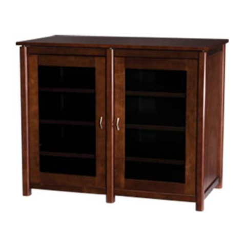
Assembly instructions for Model: CFV69
Thank you for choosing Sanus Systems Component Furniture. Please check carefully to make sure there are no missing or
defective parts. Never use defective parts. Improper assembly may cause damage or serious injury. If you have any ques-
tions regarding this product, contact Sanus at 800.359.5520 or visit www.sanus.com. Our customer service representatives
can quickly assist you with missing or damaged parts. Replacement parts for Sanus products purchased through authorized
dealers can be shipped directly to you. Please call Sanus Systems before returning products to the point of purchase.
Required Tools: Phillips screw driver
NOTE: Check to make sure all of the parts and hardware are accounted for.
Hardware: Shown at actual size.
Sanus Systems 2221 Hwy 36 West, Saint Paul, MN 55113 02.16.06 (000022)
Customer Service: 800.359.5520. See complementary Sanus products at www.sanus.com
Carpet Spike & Nut - A
Qty. 4
Back Panel Bolt - D
Qty. 12
Back Panel Spacer - C
Qty. 12
Cam Pin - B
Qty. 8
Dowel - H
Qty. 6
Shelf Pin - G
Qty. 8
Glass Shelf Pin - F
Qty. 4
Mounting Block Screw - E
Qty. 8
Threaded Cam Pin - I
Qty. 4 Isolation Pad - L
Qty. 8
Barrel Nut Bolt - K
Qty. 4
Barrel Nut - J
Qty. 4
Knob Bolt - O
Qty. 2
Wood Screw - N
Qty. 4
Bottom Shelf Pin - M
Qty. 4
Knob - P
Qty. 2
Allen Key - S
Qty. 1
Hinge Plate Screw - R
Qty. 8
Hinge Screw - Q
Qty. 8
Parts:
Foot - T
Qty. 4 Cntr. Panel Mtg. Block - U
Qty. 4 Bottom Shelf Retainer - V
Qty. 2 Hinge - W
Qty. 4 Hinge Plate - X
Qty. 4
Top - Y
Qty. 1
Bottom Shelf - Z
Qty. 1
Front Rail - AA
Qty. 2 Back Rail - BB
Qty. 2
Outer Back Panel - CC
Qty. 2
Glass Shelf - FF
Qty. 2
Isolation Shelf - EE
Qty. 2
Center Back Panel - DD
Qty. 1
Side Panel - GG
Qty. 2 Right Center Divider - II
Qty. 1
Left Center Divider - HH
Qty. 1
Center Panel - JJ
Qty. 1 Side Door - KK
Qty. 2
Step 1: Add feet
WARNING: The ends of the Carpet Spikes are very sharp and may scratch floors or furniture. All sharp objects
can be hazardous to children. For this reason Sanus Systems provides the carpet spikes as an option. Sanus
Systems will not be liable for damage or injury.
Add a Foot (T) to the Pillar of each Side Panel (GG) as shown in Diagram 1. If you wish to install the Carpet Spikes (A),
thread each Carpet Spike into the Foot as seen in Diagram 1. To adjust the height of the Carpet Spike, simply thread it in or
out; then, snug the Nut against the base of the Foot to lock the Carpet spike in place.
Diagram 1
Step 2: Attach the lower Front and Back Rails to the first Side Panel
NOTE: Make sure the flange on the Front Rail (AA) faces the back of the unit.
Attach the Front Rail (AA) to the Side Panel (GG) by sliding the Clamp down the groove in the Side Panel Pillar as shown in
Top View A. Once the Front Rail is positioned at the bottom of the groove and resting on the Foot (T), tighten theAllen Bolt
on the back side of the Front Rail so the clamp widens to hold the Front Rail firmly in place.
NOTE: Make sure the arrow on each Cam is facing the hole in the outside of the Back Rail (BB).
Insert two Cam Pins (B) into each end of the Back Rail (BB) as shown in the Detail View of Diagram 2. Insert the Cam Pins
until there is a small space between the head of the Cam Pin and the Back Rail.
Attach the Back Rail (BB) by sliding the Cam Pins (B) down the groove on the Side Panel (GG) Pillar as shown in Top
View B. Once the Back Rail is resting on the Foot, tighten the Cams labeled in the Detail View of Diagram 2 to hold them in
place. Make sure the Back Rail is oriented so the threaded holes near the ends are on the top, and the Cams face inside
the cabinet, as shown in Diagram 2.
Diagram 2
Top View A
(Front Left Corner) Top View B
(Back Left Corner)
Allen
Bolt
Clamp
AA
GG BB
GG
Cam BB
B
Pillar
T
A
GG
Spike
Nut
Detail View
GG
AA BB
Cam
Pin
(B)
AA Flange
T
Step 3: Add second Side Panel Assembly
Attach the second Side Panel Assembly (GG) by sliding the clamp in the Front Rail (AA) and the Cam Pins (B) in the Back
Rail (BB) down the grooves in the Pillars on the Side Panel until they are at the bottom of the Pillar and resting on the Foot
(T). Use theAllen Key (S) to tighten theAllen Bolt in the back of the Front Rail to widen the clamp and secure it to the Pillar.
Tighten the two Cams in the Back Rail (BB) to secure it to the Pillar.
Top View Top View
(Front Right Corner) (Back Right Corner)
Diagram 3
Step 4: Add Bottom Shelf
Thread a Bottom Shelf Pin (M) into the Side Panel (GG) as shown in Diagram 4. Repeat this process until all four Bottom
Shelf Pins have been inserted into both Side Panels.
Press fit the Bottom Shelf (Z) until it is locked into the Bottom Shelf Pins (M).
Diagram 4
BB
AA
GG
BB
AA
Allen
Bolt
Clamp
GG Allen
Bolt
GG
Cam
Pin
(B)
GG
Z
M
GG
ZGG
T
T
Step 5: Add Center Dividers
Insert a Barrel Nut (J) into the top and bottom of the Left and Right Center Dividers (HH,II) as in Detail A, Diagram 5.
NOTE: Make sure the threaded hole in the Barrel Nut (J) lines up with the hole in the back of the Center Dividers
(HH,II), and the arrow on the Cam is pointing toward the hole in the bottom as in Detail B, Diagram 5.
Insert four Threaded Cam Pins (I) into the Bottom Shelf (Z) as in Detail C, Diagram 5.
Tighten each Threaded Cam Pin (I).
Attach the Center Dividers (HH,II) to the Bottom Shelf (Z); then, tighten each Cam with a phillips screw driver, turning the
Cam clockwise.
Diagram 5
HH
II
Z
Detail A Detail B
Detail C
HH or II
J
Cam
IZ
Step 6: Add Top Rails
NOTE: Make sure the Flange on the Front Rail (AA) faces the back of the unit.
Attach the Front Rail (AA) to the Side Panel Assemblies (GG) by sliding the clamp down the groove in each Side Panel
Pillar as done in Step 2. When Front Rail (AA) is level with the tops of the Center Dividers (HH,II), tighten the Allen Bolt on
the back side of the Front Rail to expand the clamp, thus holding the Front Rail firmly in place.
NOTE: Make sure the arrow on each Cam is facing the hole in the outside of the Back Rail (BB).
Insert two Cam Pins (B) into each end of the Back Rail (BB) until there is a small space between the head of the Cam Pin
and the Back Rail as shown in Diagram 6.
Attach the Back Rail (BB) by sliding the Cam Pin (B) down the groove on the Side Panel Pillar. Once the top of the Back
Rail is level with the top of the Center Dividers (HH,II), tighten each Cam with a phillips screw driver, turning the Cam
clockwise.
Diagram 6
AA Flange
Step 7: Add Barrel Nut Bolts
NOTE: You may need to loosen Cams tightened in Step 6 to Line up the holes. If you do, make sure to tighten them
when finished with this Step.
Thread the Barrel Nut Bolts (K) through the Back Rail (BB) and into the Center Divider Panels (HH,II); then,tighten the
Barrel Nut Bolts (K) until the Back Rail (BB) is secured to the Center Divider Panels (HH,II).
Diagram 7
HH II
AA
BB BB
Cam
B
GG
GG
II BB HH
BB
K
Step 8: Add Bottom Shelf Retainer
Gently rotate the cabinet so it is resting on its back; then, using the Wood Screws (N) secure the Bottom Shelf Retainers
(V) to the Bottom Shelf (Z).
Diagram 8
Step 9: Add the Back Panels
Insert a Back Panel Bolt (D) through the Outer Back Panels (CC), Center Back Panel (DD), and a Spacer (C); then, thread
it into the Back Rail (BB). Repeat the process until all 12 Back Panel Bolts are attached to the Back Rails. Tighten the Back
Panel Bolts.
Diagram 9
NVZNV
CDBB
CC
DD
CC
BB
CC
Step 10: Add Top
Insert a Dowel (H) into each hole in the bottom of the Top (Y).
Align the Dowels (H) in the bottom of the Top (Y) with the holes in the Center Dividers (HH,II) and the pillars on the Side
Panels (GG); then, press fit the Top onto the Side Panels, and Center Dividers.
Diagram 10
Step 11: Add Isolation Pads to Isolation Shelf
NOTE: Make sure the soft side of the Isolation Pad is facing toward the shelf when inserting it into the Isolation
Shelf.
Pull the adhesive backing from the soft side of the Isolation Pads (L) and press them into the holes in the Isolation
Shelf (EE).
Diagram 11
HH
H
Y
H
II
GG
GG
L
EE
Step 12: Add Isolation Shelves
Insert two Shelf Pins (G) per Side Panel Assembly (GG) and two Shelf Pins per Center Divider (HH, II) at the desired
height.
Align the holes on the bottom side of the Isolation Shelves (EE) with the Shelf Pins (G), and place the Isolation Shelf on the
Shelf Pins.
Repeat the process for the second Isolation Shelf.
You can level the Isolation Shelves by adjusting the Screw in the Shelf Pin with an Allen Key; then, locking it with the Nut.
Diagram 12
Step 13: Add Glass Shelf
Insert four Glass Shelf Pins (F) at the desired height into the Center Dividers (HH,II).
Place the Glass Shelf (FF) on the Glass Shelf Pins.
Diagram 13
G
Screw
HH
EE
GG G
GG
EE
II
Nut
GG EE
HH FFF II
F
FF
Step 14: Add Center Panel Mounting Blocks
Attach the Center Panel Mounting Blocks (U) to the Center Dividers (HH,II) by threading the Mounting Block Screws (E)
through the Mounting Blocks and into the Center Dividers.
Tighten each Mounting Block Screw with a phillips screw driver.
Repeat until all four Mounting Blocks are in place.
Diagram 14
Step 15: Attach Center Panel
Press the Center Panel (JJ) onto the Mounting Blocks (U).
Diagram 15
HH U
II
U
E
U
JJ
U
U
Step 16: Prepare the Doors
Insert a Knob Bolt (O) through the backside of the Side Door (KK) and thread it into the Knob (P). Tighten the Knob until it
is flush with the front side of the Side Door. Perform this procedure for both Side Doors.
Diagram 16
Step 17: Attach Hinge to Side Door
Attach the Hinges (W) to the Side Doors (KK) by threading a Hinge Screw (Q) through each hole in the Hinge and into the
Side Door.
Tighten each Hinge screw until the Hinge is secure to the Side Door. Perform this procedure for both Doors.
Diagram 17
O
KK
P
KK
W
Q
Step 18: Add Side Doors
Attach the Hinge Plates (X) by threading a Hinge Plate Screw (R) through each hole in the Hinge Plate and into the Side
Panel (GG). Repeat this process until all four Hinge Plates are attached; then, tighten the Hinge Plate Screws with a phillips
screw driver.
NOTE: To attach each Hinge (W) to its Hinge Plate (X), the bolt along
the back center of the Hinge Plate must be loose during installation.
The slot on the end of the Hinge (W) will fit around the bolt on the Hinge Plate (X). The top and bottom Hinges should engage
at the same time. Once the two parts of the Hinge are mated, tighten the bolt on the Hinge Plate. Perform this procedure for
both Doors. Diagram 18
Step 19: Hinge Adjustment
Each hinge Assembly is adjustable in multiple directions.
Side Adjustment Depth Adjustment Height Adjustment
Sanus Systems 2221 Hwy 36 West, Saint Paul, MN 55113 02.16.06 (000022)
Customer Service: 800.359.5520. See complementary Sanus products at www.sanus.com
Diagram 19
This bolt must be loose.
W
R
X
+ 0.5 mm
- 3.5 mm
+ 0.5 mm
- 2.5 mm
+/- 1.5 mm
GG

Other Sanus Systems Indoor Furnishing manuals
Sanus Systems NF203 Installation guide

Sanus Systems

Sanus Systems NF203 Installation guide

Sanus Systems CFA56 User manual

Sanus Systems

Sanus Systems CFA56 User manual

Sanus Systems T20/20 User manual

Sanus Systems

Sanus Systems T20/20 User manual

Sanus Systems DFV50 User manual

Sanus Systems

Sanus Systems DFV50 User manual

Sanus Systems Accurate Furniture AFV48 User manual

Sanus Systems

Sanus Systems Accurate Furniture AFV48 User manual

Sanus Systems DFAV230 User manual

Sanus Systems

Sanus Systems DFAV230 User manual

Sanus Systems PFV47 User manual

Sanus Systems

Sanus Systems PFV47 User manual

Sanus Systems JFBD1 User manual

Sanus Systems

Sanus Systems JFBD1 User manual
Sanus Systems Sanus Natural AV Foundations NFAV230 User manual

Sanus Systems

Sanus Systems Sanus Natural AV Foundations NFAV230 User manual

Sanus Systems NFV249 User manual

Sanus Systems

Sanus Systems NFV249 User manual

Sanus Systems NF203 User manual

Sanus Systems

Sanus Systems NF203 User manual

Sanus Systems EFVS-II User manual

Sanus Systems

Sanus Systems EFVS-II User manual

Sanus Systems Sanus Foundations BFV145-B1 User manual

Sanus Systems

Sanus Systems Sanus Foundations BFV145-B1 User manual

Sanus Systems Sanus Steel Furniture SFV49  SFV49 SFV49 User manual

Sanus Systems

Sanus Systems Sanus Steel Furniture SFV49 SFV49 SFV49 User manual

Sanus Systems SFV65 User manual

Sanus Systems

Sanus Systems SFV65 User manual

Sanus Systems NFCD User manual

Sanus Systems

Sanus Systems NFCD User manual

Sanus Systems WFA37 Installation guide

Sanus Systems

Sanus Systems WFA37 Installation guide

Sanus Systems Sanus Platinum Video Furniture PFPL  PFPL... User manual

Sanus Systems

Sanus Systems Sanus Platinum Video Furniture PFPL PFPL... User manual

Sanus Systems WFV66 User manual

Sanus Systems

Sanus Systems WFV66 User manual
Sanus Systems CFA56 User manual

Sanus Systems

Sanus Systems CFA56 User manual

Sanus Systems AFDV User manual

Sanus Systems

Sanus Systems AFDV User manual

Sanus Systems PFV36sb-01 User manual

Sanus Systems

Sanus Systems PFV36sb-01 User manual
Sanus Systems JFBD1 User manual

Sanus Systems

Sanus Systems JFBD1 User manual

Sanus Systems VMCT User manual

Sanus Systems

Sanus Systems VMCT User manual

Popular Indoor Furnishing manuals by other brands

U-Line H-3636 Assembly

U-Line

U-Line H-3636 Assembly

Rapid Racking Garment Rack Assembly guide

Rapid Racking

Rapid Racking Garment Rack Assembly guide

World Market Netanya 597165 Assembly instructions

World Market

World Market Netanya 597165 Assembly instructions

Union Home CANGGU LVR00093 manual

Union Home

Union Home CANGGU LVR00093 manual

Opitec EasyLine Trivet quick start guide

Opitec

Opitec EasyLine Trivet quick start guide

MAJA Möbel SOUNDCONCEPT 7770 manual

MAJA Möbel

MAJA Möbel SOUNDCONCEPT 7770 manual

LAZBOY Power Storage operating instructions

LAZBOY

LAZBOY Power Storage operating instructions

Habitat Ivoine 808427 manual

Habitat

Habitat Ivoine 808427 manual

Renson Fixscreen Minimal Solar Frequently asked questions

Renson

Renson Fixscreen Minimal Solar Frequently asked questions

IKEA IDÅSEN manual

IKEA

IKEA IDÅSEN manual

Dux Alicia Sofa Assembly instructions

Dux

Dux Alicia Sofa Assembly instructions

Cooper Lighting 196HO specification

Cooper Lighting

Cooper Lighting 196HO specification

Franke RODX606 Installation and operating instructions

Franke

Franke RODX606 Installation and operating instructions

Sauder Graham Hill 422811 manual

Sauder

Sauder Graham Hill 422811 manual

WIEMANN 991720 quick start guide

WIEMANN

WIEMANN 991720 quick start guide

Home Decorators Collection BEVERLY 20303-VS43EC-AT Assembly instructions

Home Decorators Collection

Home Decorators Collection BEVERLY 20303-VS43EC-AT Assembly instructions

Powell 697-726A Assembly instructions

Powell

Powell 697-726A Assembly instructions

LÜTTENHÜTT Fenne 17 Assembly instructions

LÜTTENHÜTT

LÜTTENHÜTT Fenne 17 Assembly instructions

manuals.online logo
manuals.online logoBrands
  • About & Mission
  • Contact us
  • Privacy Policy
  • Terms and Conditions

Copyright 2025 Manuals.Online. All Rights Reserved.