3
Table of Contents
ECAIA ionizer S / ECAIA ionizer S+ .....................................................................4
A Scope of delivery ECAIA ionizer S ......................................................................5
B Name and description of individual parts ......................................................... 6
1 Installation (water inlet connector and device configuration) .......................... 8
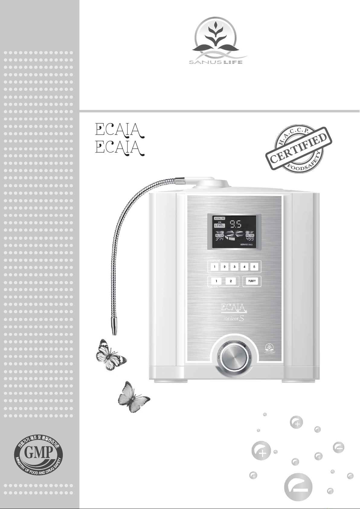
1.1 Using the quick release fastener ....................................................................................... 8
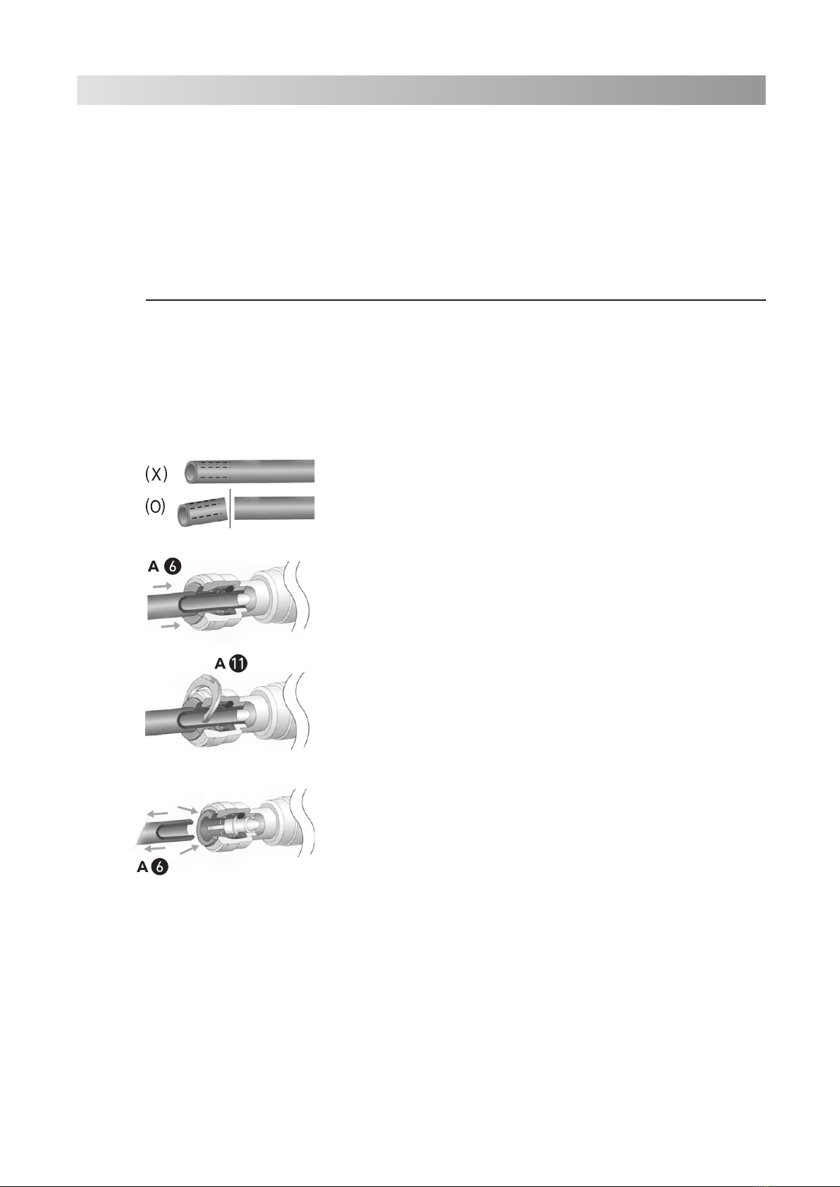
1.2 Sieve for tap water supply hose......................................................................................... 9
1.3 Temporary connection to the water tap ........................................................................... 9
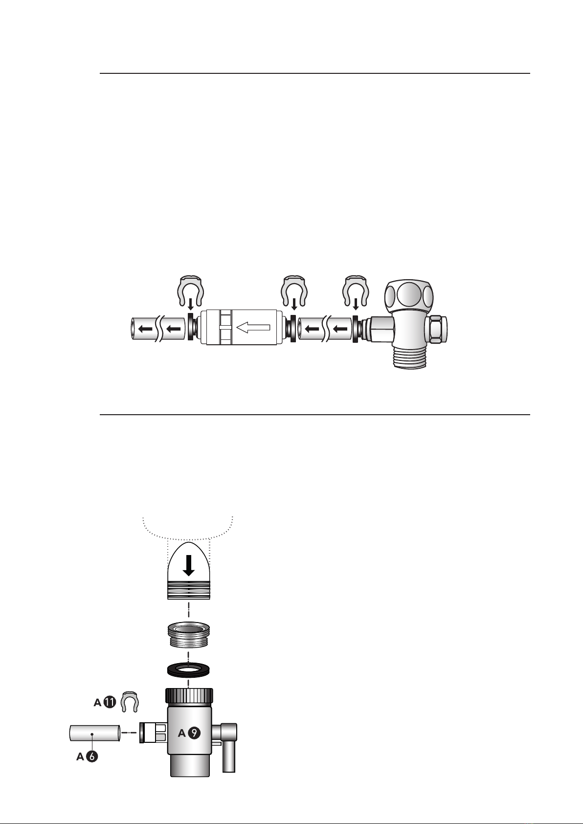
1.4 Permanent connection to the angle valve (appliance in above-counter position) ... 10
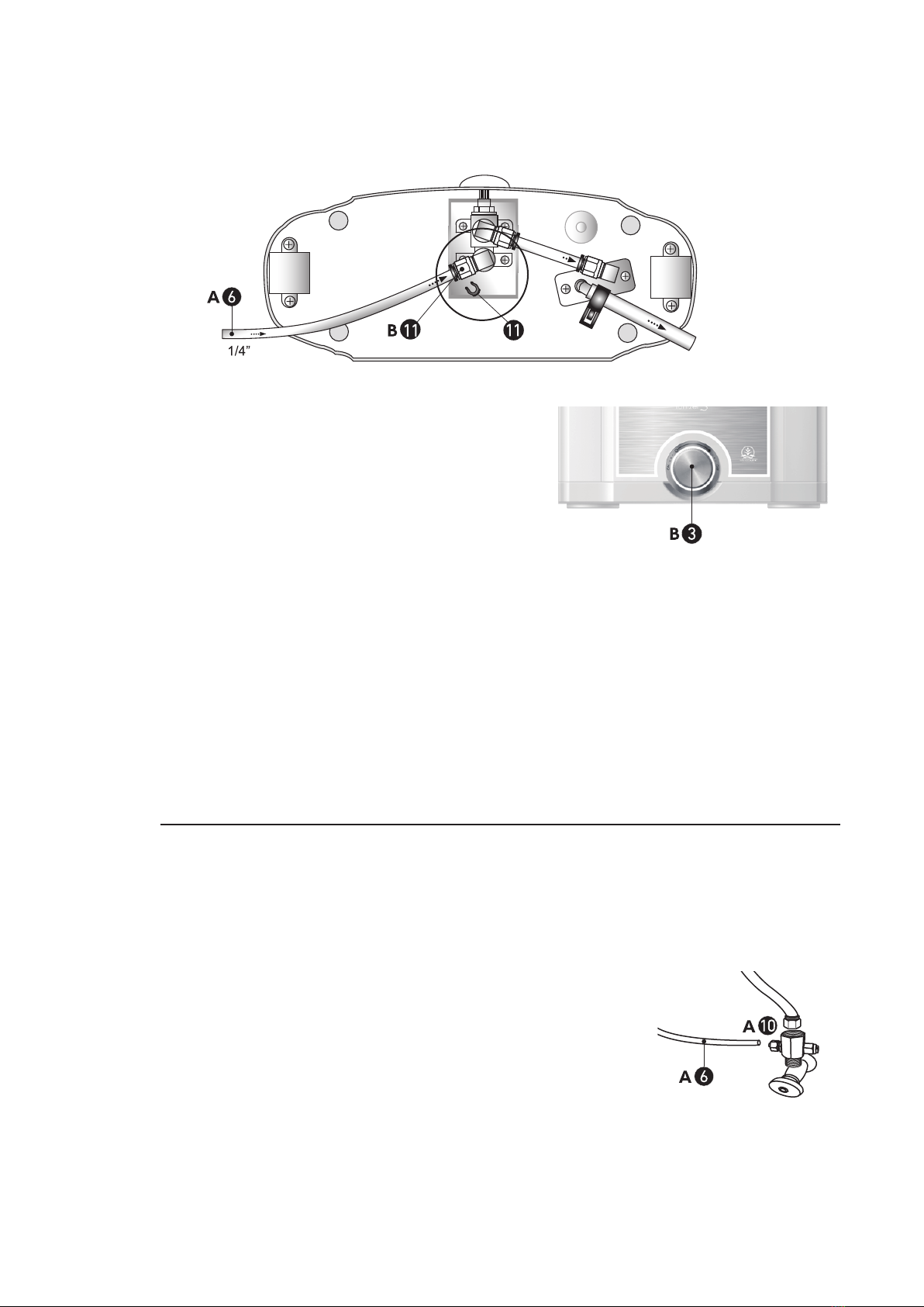
1.5 Permanent connection to the angle valve (ECAIA ionizer S+; appliance in
below-counter position; using the additional ECAIA ionizer S faucet)....................... 12
1.6 ECAIA ionizer S wall mounting ....................................................................................... 12
1.7 Assembly of the alkaline outlet hose and the acidic water tap ................................... 13
1.8 Before use .......................................................................................................................... 14
1.9 Language settings ............................................................................................................ 14
1.10 Volume configuration ....................................................................................................... 15
1.11 Flow rate configuration .................................................................................................... 16
1.12 Description of the buttons ............................................................................................... 17
1.13 Control of the ionization performance ........................................................................... 18
1.14 Setting ionization performance ....................................................................................... 19
1.15 Lower water outlet (B-12) configuration ......................................................................... 21
2 ECAIA water production ...................................................................................22
2.1 Alkaline ionized water ...................................................................................................... 22
2.2 Acidic ionized water ......................................................................................................... 23
2.3 Filtered water only ............................................................................................................ 23
2.4 Proper use of ECAIA water .............................................................................................. 24
3 Filter and filter replacement .............................................................................25
3.1 Filter shelf-life .................................................................................................................... 25
3.2 Filter replacement ............................................................................................................. 26
4 Maintenance and care .......................................................................................28
4.1 Self-cleaning function ....................................................................................................... 28
4.2 Descaling ............................................................................................................................ 29
4.3 Cleaning and disinfection ................................................................................................ 32
5 Safety instructions ............................................................................................33
6 Error and problem handling .............................................................................35
7 FAQs .................................................................................................................37
7.1 When should you measure the pH value of the ECAIA water? ................................... 37
7.2 Does the ECAIA ionizer S also work with hard water? ................................................. 37
7.3 Does the ECAIA ionizer S also work when using a descaling system? ...................... 37
7.4 What is the ORP value or the redox potential? ............................................................. 37
7.5 Can bacteria accumulate in the ECAIA ionizer S and thus
contaminate the water? .................................................................................................... 38
7.6 Does the ECAIA ionizer S also filter limescale? ............................................................ 38