54
EN
2 Scope of delivery ECAIA ionizer S faucet
1 Table of contents
ECAIA ionizer S faucet
C Scope of delivery ECAIA ionizer S faucet ....................................................................2
D ECAIA ionizer S faucet - Display ...................................................................................2
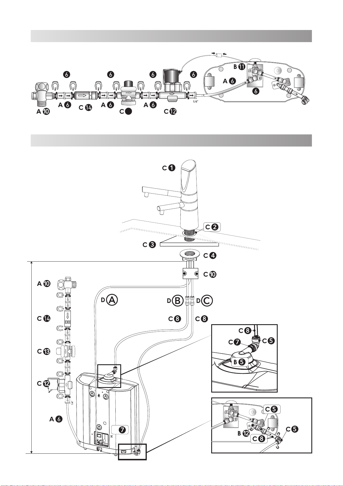
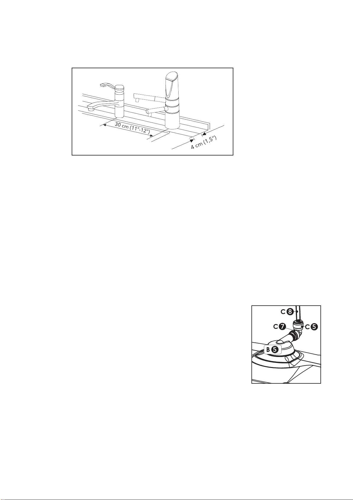
E Installation diagram (4.1) ................................................................................................3
F Installation diagram (4.2) ................................................................................................3
1 Table of contents ............................................................................................................. 4
2 Scope of delivery ECAIA ionizer S faucet ..................................................................... 4
3 ECAIA ionizer S faucet - Display ....................................................................................5
4 Installation of ECAIA ionizer S+ and ECAIA ionizer S faucet ......................................6
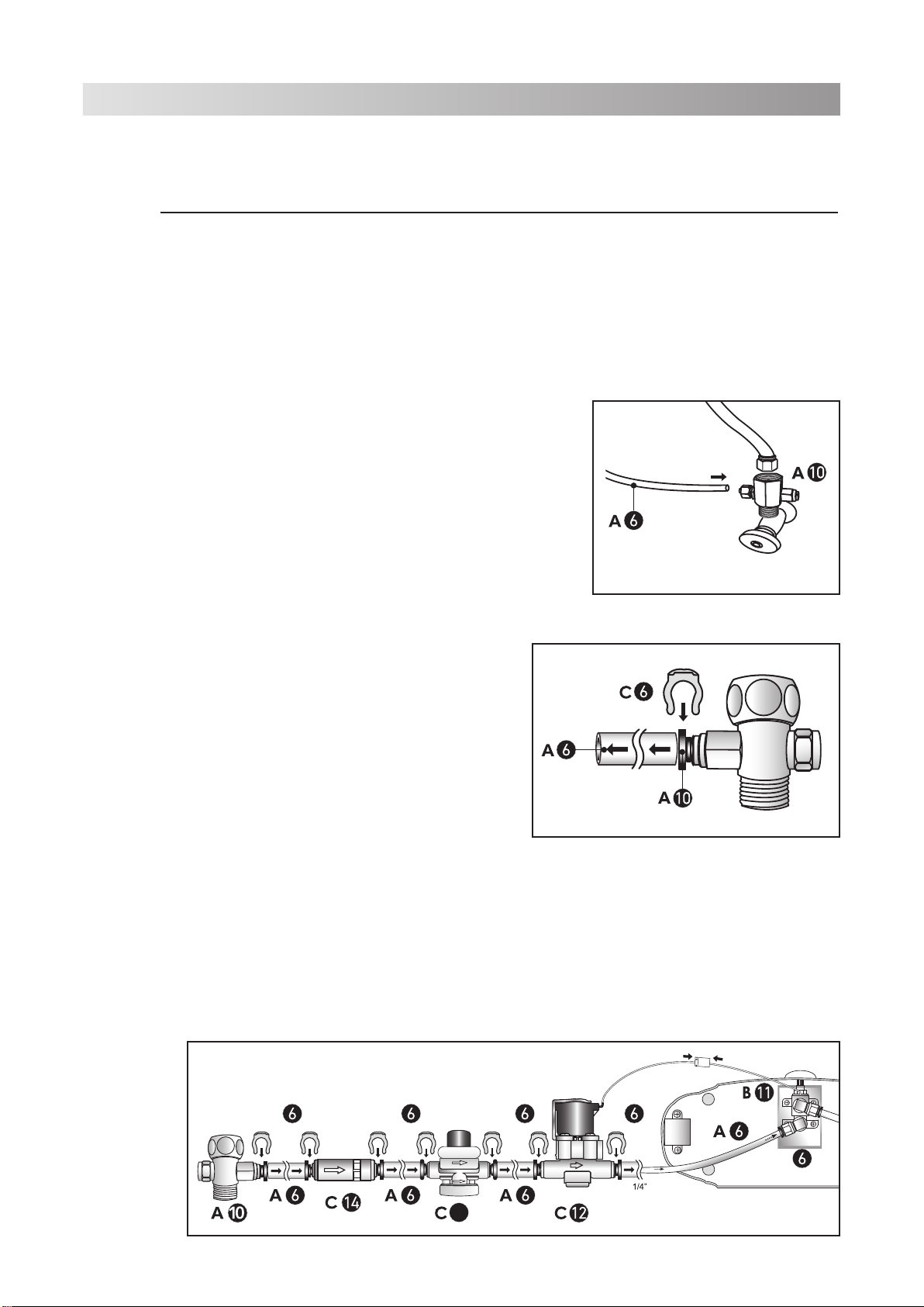
4.1 Permanent connection to the angle valve (ECAIA ionizer S+;
appliance in below counter position)........................................................................... 6
4.2 Installation of the additional ECAIA ionizer S faucet ...................................................7
4.3 Reprogramming the ECAIA ionizer S control to ECAIA ionizer S+............................ 9
4.4 Reprogramming the ECAIA ionizer S+ control to ECAIA ionizer S..........................11
4.5 Operation of ECAIA ionizer S faucet ...........................................................................12
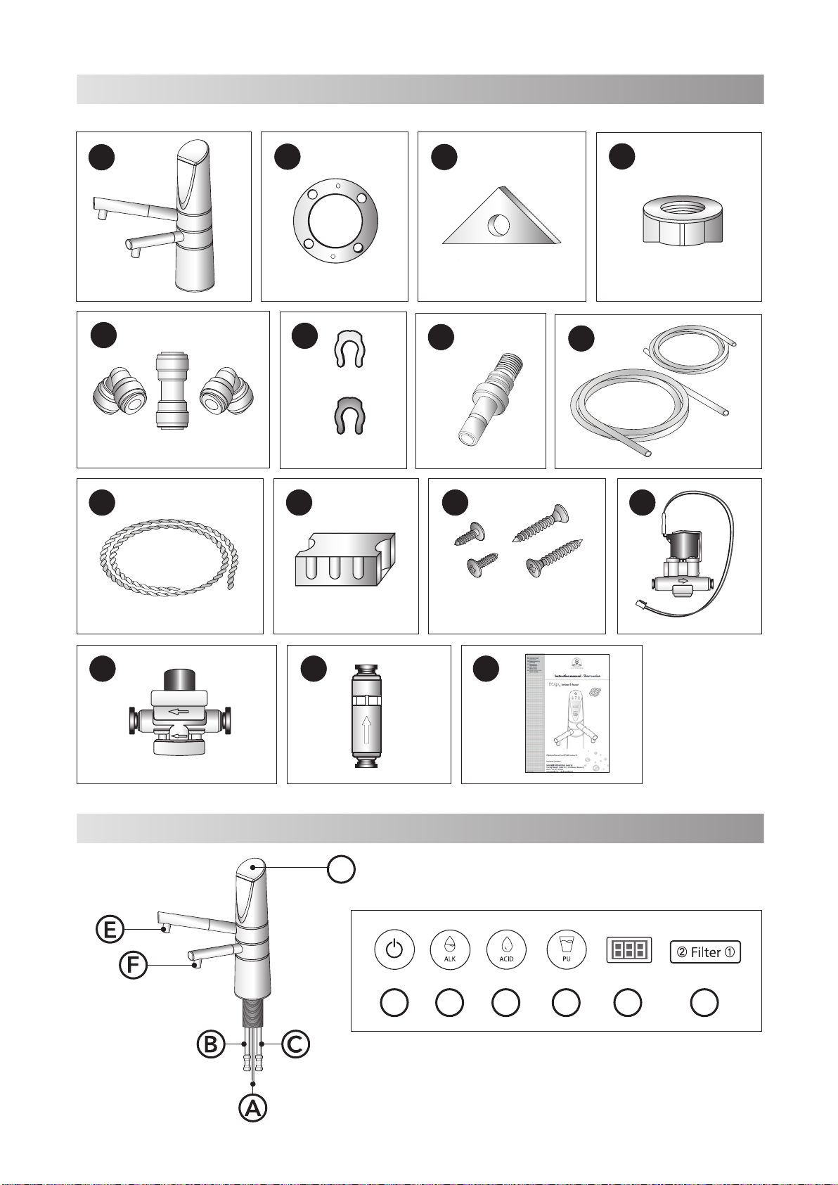
The following items are included in the scope of delivery (see Figure C on page 2).
2-way water tap - ECAIA ionizer S faucet
Seal for faucet
Reinforcing plate
Fixing nut
Quick release fastener:
1 x adapter 5/16" to 1/4"
1 x angle adapter 90° 5/16" to 5/16”
1 x angle adapter 90° 1/4" to 1/4”
Safety clips for quick release fastener:
12 x 1/4"
4 x 5/16"
Outlet adapter for alkaline water 5/16"
Water outlet hose:
1 x outlet hose for alkaline water 5/16"
1 x outlet hose for acidic water 1/4"
Cord band
Hose fixing panel (2 parts)
Screw for hose fixing panel (C-10);
2 x 3x8mm
2 x 4x16mm
Solenoid valve
Water pressure reducing valve
Filter for tap water supply hose 1/4“
Instruction manual (short version)