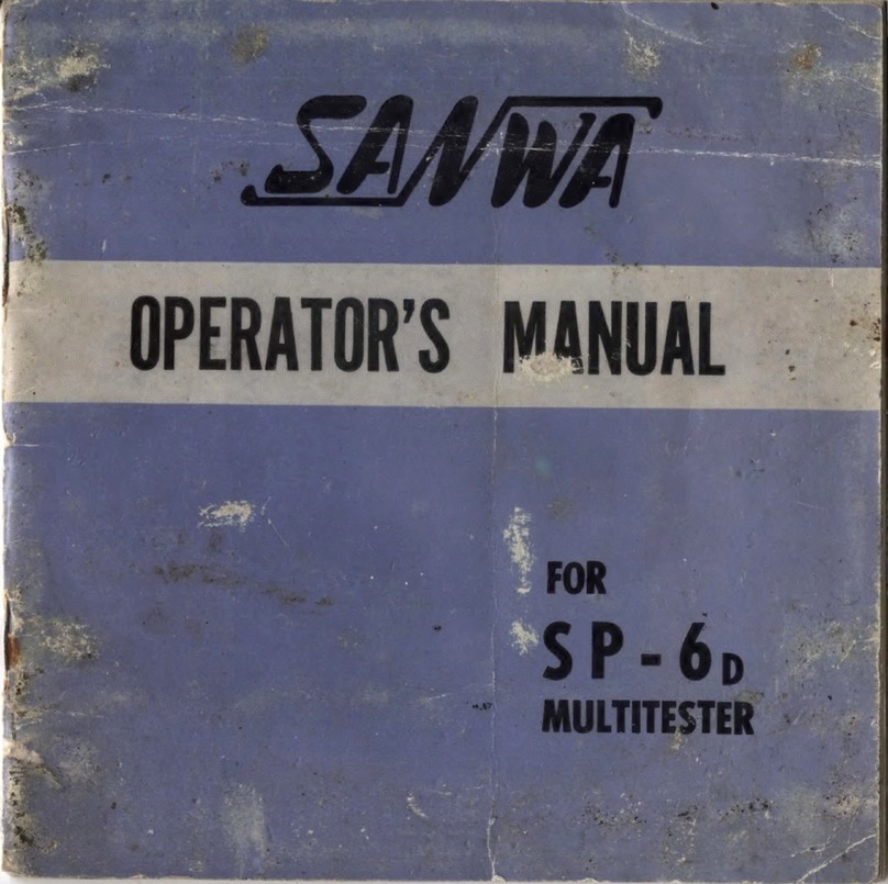
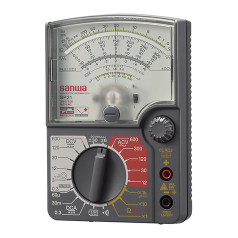
Sanwa U-50D User manual

f-% i 1


CONTENTS
GENERAL DESCRIPTION
1 Introduction .................................................................................... 2
2 Specifications.......................................................................................... 3
GENERAL INSTRUCTIONS
1 Selection of the Range ..................................................................... 4
2 Test Lead Connections ..................................................................... 4
3 Replacement of atteries ........................................................ 5
4 Reading the Scale................................................................................. 5
5 Meter Movement Protection............................................................. 5
6 Other Precautions................................................................................. 7
OPERATION
1 DC Voltage Measurements ............................................................. 8
2 AC Voltage Measurements
.............................................................
11
3 Internal Resistance of the Voltage Range .................................14
4 DC Current Measurements
.............................................................
16
5 Resistance Measurements
.................................................................
19
6 Volume Level Measurements .........................................................23
7 Capacity and High Resistance Measurements
............................
28
SUPPLEMENTARY DATA
1 Schematic Diagram ..............................................................................31
2 Arrangement of Parts (Rear View).................................................32
3 List of Main Parts ..............................................................................33
1

GENERAL DESCRIPTION
1 Introduction
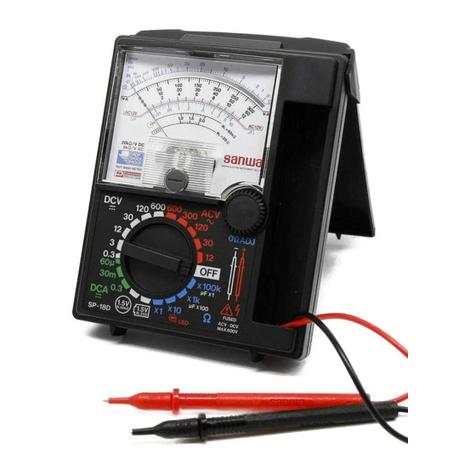
The U-50d is a pocket-size, high performance circuit
tester equipped with a meter movement of 35 micro
amperes in sensitivity.
The high internal resistance of the DC range accurately
measures voltage of high impedance circuits.
The acrylic front cover admits full light on the scale dial
with a mirror to obtain accurate reading.
The meter movement is doubly protected from damage.
The protection circuit electrically safeguards the move
ment against accidental overcurrent, and, mechanically,
the moving element is supported by spring-backed jewel
bearings to absorb shock.
Use of the battery sheaths eliminates reading error
regardless of the battery armour, magnetic or non
magnetic.
Measurement ranges of DC voltage and current can be
extended by the use of accessories available separately.
2

2 Specifications.
a Measurement Ranges Available.
DC voltage: 0. IV 0. 5V 5V 50V 250V lkV (20kn/V)
AC voltage : 2. 5V 10V 50V 250V 1000V (8kn/V)
DC current: 50/iA 0. 5mA 5mA 50mA 250mA
Resistance: Range R xl R x 10 R x 100 Rx IK
Midscale - son soon 5k n 50k n
Minimum - in ion loon lkn
Maximum- 5kn 50kn 500k n 5Mn
Volume level: — 20~ + 62d
Capacity:
Megohm: 0. 0001~0. 2/iF | use external power.
l~500M n 1
b Internal atteries. Two 1.5V dry cells. (UM-3, or equivalent)
c Allowance.
DC voltage:
AC voltage:
DC current:
Resistance :
d Size & Weight.
Within ±3% f. s. d.
Within ±4% f. s. d. (±62; for 2.5V)
Within ±3Cg f. s. d.
Within ±3°o of scale length.
131x89x43 mm & 425 gr

GENERAL INSTRUCTIONS
1 Selection of the Range
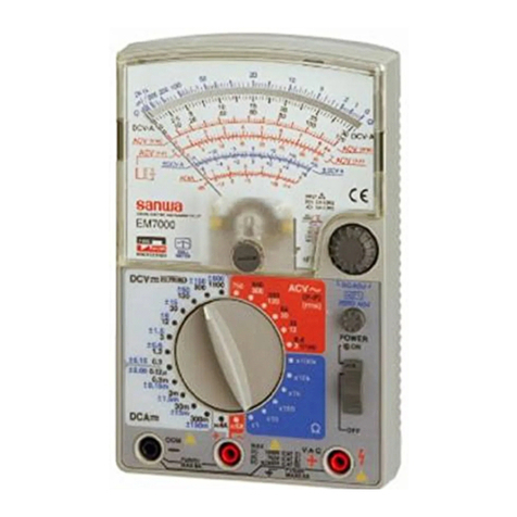
Ranges are selected by rotating the selector switch.
They are arranged around the knob, resistance ranges
on the top, AC voltage ranges on the right, DC voltage
ranges on the left, and DC current ranges on the bottom.
2 Test Lead Connections
For measurements, as a rule, the red lead is inserted in
the jack marked + and the black lead in the jack
marked —. The jack marked 0 1 V • 50//A ( + ) is for
the red lead connection for measurements on the DC 0.1
volt and 50 microampere ranges.
efore the test leads are connected to the circuit to
be measured, confirm the position of the selector
switch. If a voltage is checked when the switch is set
at a resistance or current range, the meter movement,
shunt resistor or rectifier can be permanently damaged.
L
— 4 —
j

3 Replacement of Batteries
Exhausted batteries should be immediately replaced,
because the electrolyte might leak and corrode the
internal components. For replacement, see OPERATION
-5, Note.
4 Reading the Scale
The meter should be placed level for correct reading.
Look at the scale right over where the pointer falls exact
ly over its image in the mirror.
5 Meter Movement Protection
The meter movement of the U-50o is completely pro
tected against voltages below 1000 volts which might
be accidentally impressed on any measurement range, only
by having some resistor or the rectifier burnt out. The
following table shows the resistors subject to getting
burnt when AC 1000 volts is impressed on each range :
— 5 —

Tester ranges Resistors subject
to burn Part Nos.
R x 149H R18
R x 10 505a R17
R x 100 5. 56ka R16
R x IK 47. 3k a R15
DC 0. 1V(5(VA) ?a R25
DC 0. 5V 8k R10
DC 5 V 90k a R7
DC 0. 5mA 841H • 84. 2a • 5. 41ka Rll • R12 • R19
DC 5mA 84. 2a R12
DC 50mA 7.5a R13
DC 250mA i.87a R14
AC 2. 5V 14.5-10. lka R9
AC 10V ook a R8
AC 50V 320k a R6
CAUTION. When a resistor is burnt out through
misapplication, and if the connection
mistake be left as it is, some other
resistor as well as the protection circuit,
or the meter movement itself would
suffer damage.
6

6 Other Precaurions.
a The selector switch should not be rotated leaving
the test leads connected to power: the movement
or the internal components could be damaged.
b Avoid allowing the meter to receive severe shock
or vibration. Do not leave it where there is high
temperature or moisture, or strong magnetic field.
c Do not rub the acrylic surface, or clean it with
cleaning material: anti-electrification coating will
come off to cause erroneous reading.
7

OPERATION
1 DC Voltage Measurements
DC voltage ranges are mostly used for measurements of
batteries, ( + ) power, plate, screen-grid and cathode
voltages of radio/TV receivers and amplifiers. Their
circuits generally have minus potential grounded, though
pnp transistor circuits, their plus potential.
For measurements, go through the following procedure:
a Zero Correction. efore making a measurement,
confirm the pointer to be exactly on zero of the
scale left If it is off the position, adjust it by the
8

b Range Selection. The selector switch can be
rotated to any one of the six DCV positions.
When in doubt as to the approximate voltage
present, always start with the highest range. After
the first reading, the switch can be reset to a lower
range for a more accurate reading. (Fig. 1-2)
For accurate measurements, use a range which will
allow the pointer to fall within the right hand half
of the scale.
corrector screw at the base of the scale dial. (Fig. 1-1)
Measurement of Proper range to be used
250-1000 volts 1000V
50-250 volts 250V
5-50 volts 50V
0.5-5 volts 5V
0. 1-0. 5 volts 0.5V
0-0. 1 volts 0. IV

c Test Lead Connections. See GENERAL INST
RUCTIONS^.
The test leads connected to the meter are applied
across the voltage to be measured, the red lead to
plus and the black lead to minus potential of the
load. In most cases, minus side is earthed or
connected to the chassis. When measuring, the
black lead may be fixed to the chassis, and voltage
is checked by applying the red lead to the check
point. (Fig. 1-3 & -4)
With pnp transistor circuits, the plus potential of
the battery is earthed, and the connections of the test
leads are reversed.
Wrong connections deflect the pointer to the left.
Just reverse the connections if this occurs.
d Scale Reading. Use the black scale just below the
mirror marked DCV»mA for all DC voltage measure
ments. (Fig. 1-5)
— 10 —

Ranges Scale to read : Multiplied by
0. IV 0 - 10 0.01
0.5V 0 - 50 0.01
5 V 0 - 50 0.1
50 V 0- 50 1
250 V 0- 250 1
1000V 0- 10 100
2 AC Voltage Measurements
AC voltage ranges are mostly used for checking the
mains, secondary voltages of a power transformer, etc.
Audio frequency voltages of 30-5000Hz can be meas
ured without trouble, but error might occur for higher
frequencies. The pointer will vibrate for frequencies
lower than 30Hz making it impossible to read. The
meter is calibrated for sinusoidal AC(RMS), so error
will also occur for non-sinusoidal voltages.
11 —

b Range Selection. The selector switch can be
rotated to any one of the five ACV positions.
When in doubt as to the approximate voltage
present, always start with the highest range. After
the first reading, the switch can be reset to a lower
range for a more accurate reading. (Fig. 2-2)
a Zero Correction. See 1-a. (Fig. 2-5;
I
Fig 2 i
To obtain an accurate reading, use a range which
will allow the pointer to fall within the right hand
half of the scale.

Measurement of Proper range to be used
250-1000 volts 1000V
250V
50V
10V
2.5V
50-250 volts
10-50 volts
2.5-10 volts
0-2.5 volts
c Test Lead Connections. See GENERAL INST
RUCTIONS^.
The test leads connected to the meter are applied
across the voltage to be checked. Since alternating
current is being measured, the readings are correct
to which side of the voltage the test leads are con
nected. (Fig. 2-3 & -4)
d Scale Reading. Use the red scale third from the
top marked AC 10V UP for all AC voltage measure
ments except for the 2.5 volt range, for which the
black scale below marked AC 2 5V is used. (Fig. 2-5)
13 —

Range Scale to read Multiplied by
2.5 V 0 -2 .5 1
10V 0 - 10 1
50V 0 - 50 1
250V 0 - 250 1
1000 V 0 - 10 100
3 Internal Resistance of a Voltage Range
Voltage is measured applying the test leads in parallel
with the power. Current energy (current consumption
of a voltmeter) can cause the pointer to give erroneous
reading.
Current consumption is inversely proportional to the
internal resistance of the meter: the bigger the resistance,
the less the current consumption.
As a rule, the internal resistance of a voltmeter is ex
pressed by resistance per volt using the symbol of „Q/V.
Therefore, the internal resistance of a certain voltage
range is known by the voltage value multiplied by the
Q/V
of the meter. For instance, the overall internal
resistance of the U-50o being 20,000 ohms per volt for
— 14 —

DC, the internal resistance of the 250 volt range is
250X20,000 = 5,000,000[Q) = 5,000(kl2), or 5 megohms.
When the plate or screen-grid voltage of a triode or
pentode of high impedance load and high amplification
factor along with small circuit current is checked by a
meter of small internal resistance, considerable current
flows from the meter into the series load resistance of the
tube. As a consequence, there is greater voltage drop,
and the meter reads lower than the true value: the con
nection of the meter upsets the circuit to be checked.
Error can be minimized by the use of a meter of high
internal resistance, but unless it is infinite, some error
is inevitable even if a vacuum tube voltmeter be used
for checking such a circuit.
The internal resistance of a meter little affects the check
ing of the DC voltage of (-f-) power, or plate and
screen-grid of a power tube, because their impedances are
smaller than the meter impedance. It is the control grid
voltage that is disturbed by voltage measurement.
— 15 -

a Zero Correction. See 1-a. (Fig. 3-1)
4 DC Current Measurements.
b Range Selection. The selector switch can be
rotated to any one of the five current ranges
prescribed. When in doubt as to the approximate
current present, always start with the highest range.
The switch can be reset to a lower range for a
more accurate reading. (Fig. 3-2)
To obtain an accurate reading, use a range which
will allow the pointer to fall within the right hand
half of the scale.
— lti —

Measurement of Proper range
to be used
50 - 250mA 250(mA)
5 - 50mA 50 (mA)
0.5 - 5mA 5(mA)
0. 05 - 0. 5mA 0. 5(mA)
0 -0. 05mA 50 (/i A)
c Test Lead Connections. See GENERAL INST
RUCTIONS^.
efore taking a measurement, the circuit to be
checked is opened, and the meter is connected in
series with the load by way of the test leads, the red
lead to plus and the black lead to minus potential.
(Fig. 4-3 & -4)
d Scale Reading. Use the black scale just below the
mirror marked OCV*mA for all DC current meas
urements. It is used in common with DC voltage
measurements.
— 17 —

Range | Scale to read Multiplied by
50m A 0 - 50 1
0.5mA 0 - 50 0.01
5mA 0 - 50 0.1
50mA 0 - 50 1
250mA 0 - 250 1
Note. For measurement of a low resistance circuit,
the internal resistance of the current range
used is connected in series with it resulting
in current decrease to cause erroneous
reading.
— 18 —
Table of contents
Other Sanwa Test Equipment manuals
Popular Test Equipment manuals by other brands

Wildlife Acoustics
Wildlife Acoustics Ultrasonic Calibrator quick start guide
iCarsoft
iCarsoft Honda/Acura Multi-system Scanner i990 user guide
Hanatek
Hanatek Incline Plane Tester operating manual
Lutron Electronics
Lutron Electronics RT-606 Operation manual
YOKOGAWA
YOKOGAWA DLM3022 user manual

Schleibinger
Schleibinger CDF manual
Hioki
Hioki FT4310 instruction manual
Keysight Technologies
Keysight Technologies S8780A Getting started guide
DAKOTA ULTRASONICS
DAKOTA ULTRASONICS PR-9 Operation manual
Lutron Electronics
Lutron Electronics DL-9954 Operation manual

Humanetics
Humanetics Hybrid III 5th Female user manual

Parker
Parker icountBS user manual
