Sanwa SP21 User manual

DRAWING No SP21 18-1805 2040 2040
取扱説明書
INSTRUCTION MANUAL
SP21
マルチテスタ
MULTITESTER

DRAWING No SP21 18-1805 2040 2040
目 次
【1】安全に関する項目〜ご使用前に必ずお読みください〜
【2】用途と特長
【3】各部の名称
【4】指示の読み取り方
【5】機能説明
【6】測定方法
〜
【7】保守管理について
【8】アフターサービスについて
【9】仕 様

DRAWING No SP21 18-1805 2040 2040
CONTENTS
【1】
SAFETY PRECAUTIONS:Before use,read the following safety precautions
…… 2
1-1 Explanation of Warning Symbols …………………………… 2
1-2 Warning Instruction for safe use …………………………… 2
1-3 Maximum Overload Protection Input ……………………… 4
【2】APPLICATION AND FEATURES ……………………………… 5
2-1 Application …………………………………………………… 5
2-2 Features ……………………………………………………… 5
【3】NAME OF COMPONENT UNITS……………………………… 6
【4】SCALE READING ……………………………………………… 7
【5】DESCRIPUTION OF FUNCTIONS …………………………… 9
5-1 Knob and Adjuster …………………………………………… 9
5-2 How to Use the Stand ……………………………………… 9
【6】MEASUREMENT PROCEDURE ……………………………… 11
6-1 Start-up Inspection …………………………………………… 11
6-2 How to Setup Range(Selection of a appropriate range)
… 13
6-3 Preparation for Measurement ……………………………… 13
6-4 Voltage Measurement ……………………………………… 15
6-4-1 DCV Measurement( )
……………………………… 15
6-4-2 ±DCV Measurement(±DCV )
…………………… 17
6-4-3 ACV Measurement(〜)
……………………………… 19
6-5 DCA Measurement( )
……………………………………21
6-6 Resistance Measurement(Ω)
……………………………23
6-7 Battery check …………………………………………………25
6-8 Checking Continuity( )
……………………………………27
6-9 Measuring Capacity(μF)
…………………………………29
6-10 DC High Voltage measurement(Optional HV Probe)
……31
6-11 End of Measurement …………………………………………34
【7】MAINTENANCE …………………………………………………34
7-1 Maintenance and Inspection…………………………………34
7-2 Calibration………………………………………………………34
7-3 How to Replace Battery and Fuse …………………………35
7-4 Storage …………………………………………………………38
【8】AFTER-SALE SERVICE …………………………………………38
8-1 Repair …………………………………………………………38
8-2 For Information or Enquiries …………………………………40
8-3 Sanwa Web Site ………………………………………………40
【9】SPECIFICATIONS ………………………………………………42
9-1 General Specification
…………………………………………42
9-2 Optional Accessories …………………………………………42
9-3 Measurement Range and Accuracy…………………………44
DRAWING No SP21 18-1805 2040 2040
【1】
安全に関する項目〜ご使用の前に必ずお読みください〜
1
-
1 警告マークなどの記号説明
〜
1
-
2 安全使用のための警告文
警 告

DRAWING No SP21 18-1805 2040 2040
To ensure that the meter is used safely,Be sure to observe
the instruction when using the instrument.
Protection circuit may be undermined by unjustifiable usage that
does not the guidelines in the instruction manual.
1Never use meter on the electric circuit that exceed 6 kVA.
2Pay special attention when measuring the voltage of AC 33
Vrms46.7 Vpeakor DC 70 V or more to avoid injury.
3Never apply an input signals exceeding the maximum rating
input value.
4Never use meter for measuring the line connected with
equipmenti.e.motorsthat generates induced or surge
voltage since it may exceed the maximum allowable voltage.
1
SAFETY PRECAUTIONS:Before use,read the following safety precautions
This instruction manual explains how to use your multimeter
SP21 safely. Before use,please read this manual thoroughly. After
reading it,keep it together with the product for reference to it when
necessary.
The instruction given under the headingWARNING CAUTION
must be followed to prevent accidental burn or electrical shock.
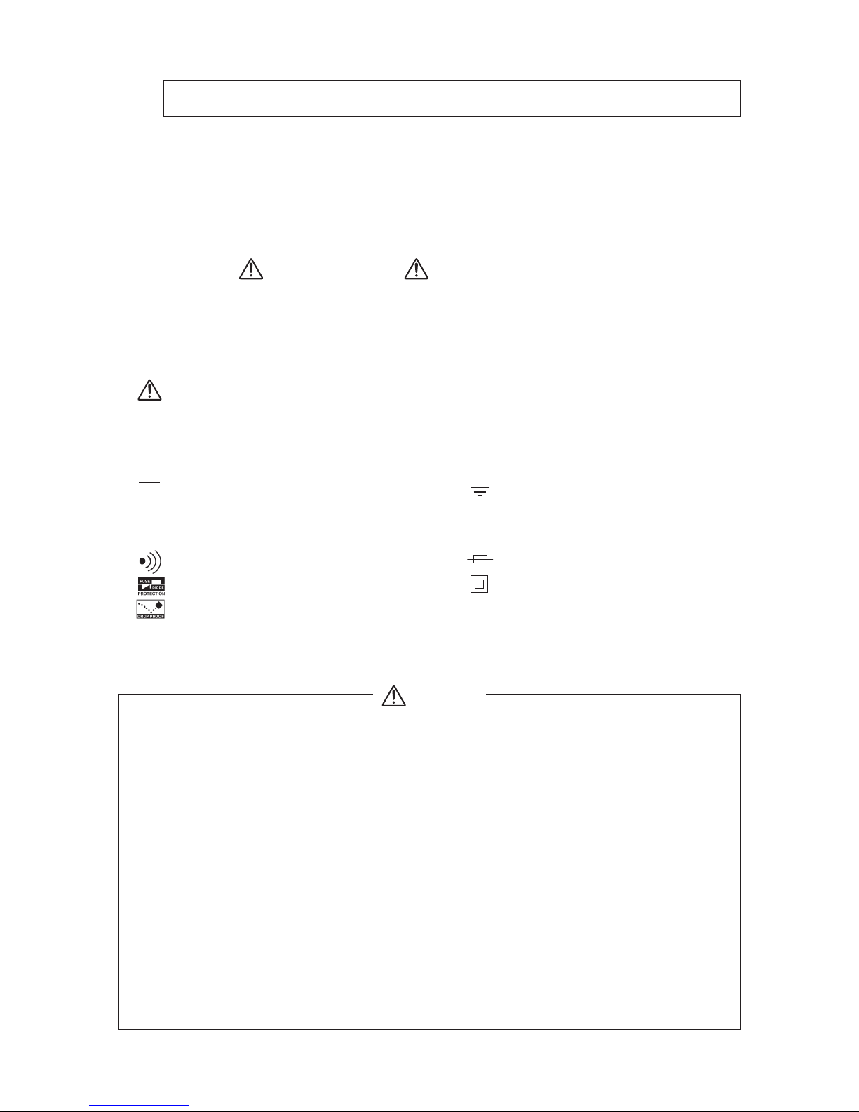
1-1 Explanation of Warning Symbols
The meaning of the symbols used in this manual and attached to
the product is as follows.
Very important instruction for safe use.
The warning messages are intended to prevent accidents to
operating personnel such as burn and electrical shock.
The caution messages are intended to prevent damage to
the instrument.
DC Voltage Glaund
AC Voltage Plus input
Resistance Minus input
Continuity Fuse
Fuse & Diode protection Double insulation
Drop proof
1-2 Warning Instruction for safe use
WARNING
Table of contents
Other Sanwa Test Equipment manuals


Popular Test Equipment manuals by other brands


Redtech
Redtech TRAILERteck T05 user manual

Venmar
Venmar AVS Constructo 1.0 HRV user guide

Test Instrument Solutions
Test Instrument Solutions SafetyPAT operating manual

Hanna Instruments
Hanna Instruments HI 38078 instruction manual

Kistler
Kistler 5495C Series instruction manual

Waygate Technologies
Waygate Technologies DM5E Basic quick start guide

StoneL
StoneL DeviceNet CK464002A manual

Seica
Seica RAPID 220 Site preparation guide

Kingfisher
Kingfisher KI7400 Series Training manual

Kurth Electronic
Kurth Electronic CCTS-03 operating manual

SMART
SMART KANAAD SBT XTREME 3G Series user manual

Agilent Technologies
Agilent Technologies BERT Serial Getting started