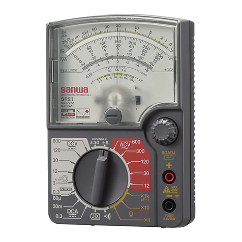
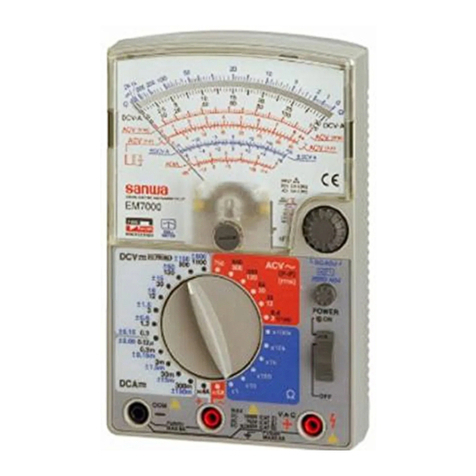
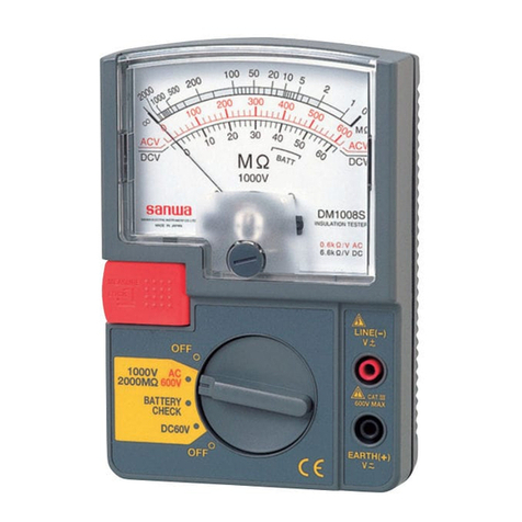
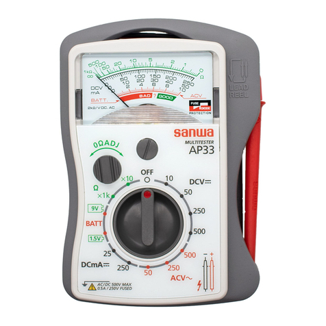
Sanwa SP-18D User manual

−
1
−
注意マークについて
安全のため、この説明書をよくご覧ください。
特に警告文は火傷
(やけど)や感電など、人身事故を防止するた
めのものです。注意文は本器を壊すおそれのあるお取り扱いに
ついての注意です。必ずお守りください。
高電圧が印加されるため、注意してください。
各部の名称
−
2
−
以下の項目は、やけど
...
や感電
..
などの人身事故を防止するための
ものです。本器をご使用する際には必ずお守りください。
1. 6kVAを超える電力ラインでは使用しないこと。
2. AC33Vrms(46.7Vpeak)またはDC70V以上の電圧は人体に危険
なため注意すること。
3. 最大定格入力値を超える信号は入力しないこと。
4. 最大過負荷入力値を超えるおそれがあるため、誘起電圧、サー
ジ電圧の発生する
(モータなど)ラインの測定はしないこと。
5. 本体またはテストリードが傷んでいたり、壊れている場合は
使用しないこと。
6. リヤケースをはずした状態では使用しないこと。
7. ヒューズは必ず指定定格および仕様のものを使用すること。
ヒューズの代用品を用いたり短絡することは絶対にしない
こと。
8. 測定中はテストリードのつばよりテストピン側を持たない
こと。
9. 測定中は他のファンクションまたは他のレンジに切り換えた
り、プラグを差し換えたりしないこと。
10. 測定ごとのレンジおよびファンクション確認を確実に行う
こと。
11. 本器または手が水などでぬれた状態での使用はしないこと。
12. テストリードは指定タイプのものを使用すること。
13. 内蔵電池および内蔵ヒューズ交換を除く修理・改造は行わな
いこと。
14. 年1回以上の点検は必ず行うこと。
15. 屋内で使用すること。
安全測定のための警告文
−
3
−
警告
測定ごとの「レンジ確認」を、確実に行ってください。
測定標準
●メータの0位調整:指針が0位置に合うよう、メータ0位調整器を回
します。中形マイナスねじ回しを用います。
●レンジ切換えつまみにより目的の測定レンジを選定します。
直流電圧(DCV )の測定 最大測定電圧DC600V
電池などの電圧を、以下の順序で測ります。
1. レンジ切換えつまみを、最適な位置(メモ参照)に合わせる。
2. 被測定回路のマイナス電位側に黒テストピンを、プラス電位側に
赤テストピンをそれぞれ当てる。
3. メータの振れを読みとる。
注意
電圧は負荷と並列接続で
測定します。
最適なレンジ位置:6Vを測定する場合は12Vレンジ、15Vを測定す
る場合は30Vレンジのように、測定する値より大きく、かつ近い
レンジを選びます。
測定値の見当がつかない場合は、最大レンジ
(600V)で測定してみます。
●乾電池やボタン型電池の電圧を単体の状態で測定する場合は、6頁
の「電池負荷電圧の測定」をご参照ください。
●脈流電圧の測定では、その平均値を指示します。
メ モ
−
4
−
交流電圧(ACV〜)の測定 最大測定電圧AC600V
電灯線などの電圧を、以下の順序で測ります。
1. レンジ切換えつまみを最適な位置(3頁のメモ参照)に合わせる。
2. 被測定回路にテストピンを、赤黒に関係なく当てる。
3. メータの振れを読みとる。
●波形の影響:正弦波以外の波形測定では、誤差を生じます。
●周波数の影響:周波数が高くなると誤差が大きくなります。
AC12Vレンジは70kHz
以下、AC30Vレンジは
20kHz以下でご使用く
ださい。
●インバータ電源回路の測定:
実際の電圧値より大き
く指示するなど、誤動
作することがあります。
直流電流(DCA )の測定 最大測定電流DC0.3A
警告
電流測定は、負荷と直列になるよう接続します。
そして電圧をかけることのないよう、ご注意ください。
DC0.3Aまでの電流を以下の順序で測ります。
1. レンジ切換えつまみを、最適な位置(3頁のメモ参照)に合わせる。
2. 被測定回路を切離し、被測定回路のマ
イナス電位側に黒テストピン、プラス
電位側に赤テストピンをそれぞれ接続
する。
3. メータの振れを読みとる。
回路を切りはなす
−
5
−
抵抗(Ω)の測定 最大測定抵抗200MΩ
警告
電圧が加わっている電路の抵抗測定はできません。
0〜200MΩの抵抗を、以下の順序で測ります。
1. レンジ切換えつまみを最適な位置に合わせる。
・×1レンジ:0〜200Ω程度の測定に用いる。
・×10レンジ:20Ω〜2kΩ程度の測定に用いる。
・×1kレンジ:2kΩ〜200kΩ程度の測定に用いる。
・×100kレンジ:200kΩ〜200MΩの測定に用いる。
2. テストピンの赤黒をショートして、指針が0Ωに振れるよう、0Ω
調整つまみを回して合わせる。
(指針が0Ωまで振れないときは、
内蔵電池を交換する)
3. 赤黒テストピンを、被測定抵抗に当てる。
4. メータの振れを読みとる。
●Ωレンジの極性:Ωレンジでは、赤テス
トピンがマイナス電位に、黒テストピン
がプラス電位になります。したがって、
ダイオードの導通テストでは、赤テスト
ピンをカソード側に、黒テストピンをア
ノード側に当ててチェックします。
●本器のΩレンジは3Vで動作させていますから、LEDの点灯テストが
できます。×10レンジでのテストが最適です。
●テストピンに指を触れて測定すると人体の抵抗の影響を受け誤差
を生じます。(特に×1kと×100kレンジ)
●ヒューズの抵抗:定格(0.5A)より小さなヒューズや消弧剤入りヒュー
ズなどをご使用になると、ヒューズ抵抗の影響で、×1レンジの0Ω
調整ができません。同仕様、同定格のヒューズをご使用ください。
注:×1レンジでは、電池の消費電流が大きく、指針が1度
行った0Ω調整点からズレることがあります。
−
6
−
電池負荷電圧の測定
●の測定(RL=20Ω)
マンガン電池R20
(単1形),R14(単2形),R6(単3形)やアルカリ電
池LR20(単1形),LR14(単2形),LR6(単3形)の、20Ω負荷時にお
ける電圧を測定できます。
したがって、使用状態に近い電池チェックが行えます。
1. レンジ切換えつまみを 位置に合わせる。
2. 被測定電池に、赤黒テストピンを当てる。
3. メータの振れを読みとる。
1.5V
1.5V
注意
ボタン型電池の測定はしな
いでください。
●の測定(RL=60kΩ)
アルカリボタン電池(LR43,LR44など)や酸化銀ボタン電池
(SR43,SR44など)などのボタン電池の電圧測定を、 位置にレ
ンジ切換えつまみを合わせ、前項同様に測定します。
静電容量(μF)の測定
大容量コンデンサの概略値を測定します。
1. コンデンサの端子をショートして、
電荷を放電する。
2. レンジ切換えつまみで、μF×1か、μF×100を選定する。
3. 抵抗(Ω)レンジ同様、0 Ω調整をする。
4. テストピンをコンデンサの端子に当てる。
(有極性コンデンサでは、
●極側がテストピンの黒となるようにする)
5. メータ指針の振れの最大到達点をμF目盛で読みとる。
注:電気二重層コンデンサの測定はできません。
1.5V
1.5V
−
7
−
目盛板の読みとりかた
ご使用のレンジ 読みとり倍率
Ω×100k ×100k
Ω×1k ×1k
Ω×10 ×10
Ω×1 ×1
DCV30 ×0.1
DCV3 ×0.01
DCV0.3 ×0.001
ACV300 ×1
ACV30 ×0.1
DCA0.3 ×0.001
DCA30m ×0.1
DCV600 ×10
ACV600 ×10
DCA60μ ×1
①
②
③
ご使用のレンジ 読みとり倍率
DCV120 ×10
DCV12 ×1
ACV120 ×10
ACV12 ×1
μF×100 ×100
μF×1 ×1
×1
×1
④
⑤
⑥
⑦
⑧
1.5V
1.5V
*1. DCV.DCA.ACVの各レンジ
は、V.A目盛線とこの数字列
で指示値を求めます。
*2. AC12Vレンジ専用目盛です。
−
8
−
ハンドストラップ、保護カバー、テストリードについて
ハンドストラップの取付けかた
1. 取付けねじをゆるめて、リヤケ
ースをパネルからはずします。
2. ハンドストラップの金具側を、
パネル上方の突起部にはめます。
(右図)
3. リヤケースを元どおりパネルに
しっかりはめ、ねじ止めします。
保護カバーの使い方
1. 本器を使わないと
きには、パネル面
へ取付けて、保管
してください。
(a図)
2. 測定をするときに
は、リヤケース面
へピッタリ取付け
ます。(b図)のように先端部をパネル上方に結合して、スタンド
としても使用できます。
テストリードの収納
本器を使わないときには、右図のようにテス
トリードを収納スペースに収納してください。
収納方法は、リード線を小さく3回ほど巻き、
収納スペースに入れ、その後でテスト棒をテ
ストピン側から入れると容易に行えます。
−
9
−
電池、ヒューズの交換方法
内蔵電池の交換方法
1. 取付けねじをゆるめリヤケースをパネル
からはずします。
2. 消耗した電池を2本ともはずし、新品の
電池と交換します。
の極性をまちがえぬよう注意し、
電池ホルダにしっかり入れてください。
3. リヤケースをパネルにねじ止めします。
内蔵ヒューズの交換方法
ΩやDCA、 レンジに誤って電灯線電圧
(100V)などを加えますと、ヒューズが切れ
て回路を保護します。
Ωレンジでメータを振らせる操作をしても(5頁参照)
、メータがまった
く振れない原因は、ヒューズの切れがほとんどです。
1.5V
警告
●ヒューズは安全や性能を維持するため、同定格のもの
(0.5A/250V)をご使用ください。
(入手しにくい場合は、
当社へご注文ください)
また、別定格のヒューズを用いたりヒューズホルダ端子
間を銅線などで短絡することは絶対にしてはいけません。
●リヤケースをはずしたとき、ヒューズおよび電池以外の、
内部の部品や配線に手を触れないでください。
1. ヒューズの交換は、リヤケースをはずし、回路基板上のホルダか
ら熔断したヒューズを抜きとり、新品ヒューズと差換えます。
2. リヤケースを元どおりねじ止めしてから、各レンジの指示が正常
かどうかをチェックします。
●内蔵電池左側の予備ヒューズをご使用ください。
(上図参照)
−
10
−
お取扱い上の一般的なご注意
1. 振動:モータバイク積載など過度な振動は、メータ故障の原因に
なります。避けてください。
2. 環境:直射日光下、高温(60℃以上)
、多湿(85%以上)
、結露す
る場所に長時間、置かないでください。
3. 帯電: メータカバーは、帯電防止処理がしてあります。
布などで強くこすらないでください。
長年のご使用で帯電した場合は、応急処置として、中性洗
剤をカバー表面に塗ると効果があります。
4. 保守:本品のお手入れは、筆や布で、軽く払う程度にとどめ、シン
ナーやアルコールなどは避けてください。
別売付属品
●
クリップアダプタ CL
−
11型
●ICテストクリップ TL
−
8IC型
最大過負荷保護入力値
ファンクション(レンジ)
最大定格入力値
各レンジ□
最大目盛値
DC1000V
AC750V
またはPEAKMAX1100V
DC,AC200V
またはPEAKMAX250V
各レンジ□
最大目盛値
各レンジ□
最大目盛値
●電流・電圧
入力禁止
DC2V
最大過負荷保護入力値
DCV120〜600
ACV120〜600
DCV0.3〜30
ACV12〜30
DCA
Ω
※
注意:AC電圧はサイン波の実効値で規定。※印は 5 秒間以内。
1.5V
1.5V
−
11
−
仕様
・測定範囲および許容差
許容差保証温湿度範囲:23±2℃、75%RH以下
測定の種類 最大目盛値 許容差 備 考
直流電圧
(DCV )
交流電圧
(ACV〜 )
直流電流
(DCA )
抵 抗
(Ω)
電 池
負荷電圧
静電容量
(μF)
0.3
3−12−30
−120−600
最大目盛値の
±3%以内
内部抵抗 5kΩ
内部抵抗
20kΩ/V
12−30−120
−300−600
最大目盛値の
±3%以内
内部抵抗 9kΩ/V
周波数特性
(変動値3%以内)
12Vレンジ30〜70kHz
30Vレンジ30〜20kHz
60μ−30m−0.3 最大目盛値の
±3%以内
電圧降下
0.3V
(ヒューズ抵抗除く)
2k−20k−2M
(×1)(×10)(×1k)
目盛の長さの
±3%以内 中央目盛 20Ω
最大目盛 2kΩ
開放電圧 3V
200M
(×100k)
目盛の長さの
±5%以内
2.0V 負荷抵抗 20Ω−−
2.0V −− 負荷抵抗 60kΩ
10−1000 概略値 充電々流による
最大振れ指示
(注)・標準姿勢(メータ指針が水平の状態に対して±5°
以内)での許
容差です。保護カバーにて、本器を傾斜させて使用した場合
(8頁参照)多少誤差が増加することがあります。
・交流電圧は正弦波交流の場合。
出荷時の電池について
工場出荷時にモニター用電池が組み込まれておりますので、記載
された電池寿命に満たないうちに切れることがあります。
モニター用電池とは製品の機能や性能をチェックするための電池
のことです。
取扱説明書1、予備ヒューズ1
(本体内蔵)、ハンド
ストラップ1
R6(単3形) 1.5V×2本
0.5A/250V φ5×20mm 速断ヒューズ
内部磁石式トートバンド機構の可動コイル形
半波整流
23±2℃,75%RH以下 結露のないこと
0〜43℃,80%RH以下 結露のないこと
−10〜50℃,70%RH以下 結露のないこと
30Hz〜80kHzの間で±3%以内(AC12Vレンジ)
−
12
−
・一般仕様
項 目 仕 様
メータ
外形寸法
本体重量
回路保護
内蔵電池
内蔵ヒューズ
メータ
AC整流方式
許容差保証温湿度範囲
使用温湿度範囲
保存温湿度範囲
周波数の影響
耐電圧
標準付属品
耐衝撃型トートバンドメータを搭載
商用電源AC250Vまでの電圧を、全レンジに5秒間
印加しても、ヒューズで保護します。
(くり返し
印加すると、ダイオードが劣化することがある)
電気回路とリヤケース間に、AC3kVを1分間加え、
試験後電気的または機械的な損傷がないこと。
159.5×129×41.5mm
約320g
用途と特徴
●
用途:本器は小容量電路の測定用に設計された携帯用の回路計で
す。小形の通信機器や家電製品、電灯線電圧や各種電池の測
定などに適します。
●特長:①メータに軽量、小形、高感度、耐ショックタイプのトート
バンド機構のものを搭載し、
携帯用として優れております。
②高抵抗(最大200MΩ)の測定ができます。
説明書中の仕様や内容については予告なしに変更中止することがございますのでご了承ください。
修理用テストリード
TL-61Tc
−
13
−
アフターサービスについて
保証期間について
本製品の保証期間は、お買い上げの日より3年間です。
ただし、日本国内で購入し日本国内でご使用いただく場合に限ります。
また、製品本体の許容差は1年保証、製品付属の電池、ヒューズ、テ
ストリード等は保証対象外とさせていただきます。
有償修理について
1. 修理をご依頼の前に:ご確認ください。
●内蔵ヒューズの切れ
●内蔵電池の消耗
●テストリードの断線
2. 修理期間:本品の補修性能部品の最低保有期間は、製造打切後6年
間です。(修理期間も準じます)
3. 修理費用:修理や輸送費用が製品価格よりかさむ場合もあります
ので、事前に発売元へご相談ください。
4. 送り先は:下記あてに「修理品在中」としてお送りください。
三和電気計器株式会社・羽村工場サービス課
〒205-8604 東京都羽村市神明台4−7−15
TEL(042)554−0113
お問合わせ先
三和電気計器
(株)
東京本社:TEL(03)3253−4871 FAX(03)3251−7022
大阪営業所:TEL
(06)6631−7361 FAX
(06)6644−3249
お客様計測相談室: 0120−51−3930
受付時間 9:30〜12:00 13:00〜17:00
(土日祭日を除く)
三和電気計器(株)ホームページ:http://www.sanwa-meter.co.jp
交換部品のご案内
●
交換用ヒューズ
交換ヒューズのお求めは上記三和電気計器株式会社・羽村工場サー
ビス課あてに、代金+送料分の切手を添えて型名、部品名を明記し
てご注文ください。
〈サイズ〉 〈定 格〉 〈単 価〉 〈送 料〉
φ5×20mm 0.5A/250V ¥40
(税込¥42) ¥120
(10本まで)
保証書
ご氏名
ご住所
様
TEL
保証期間
ご購入日 年 月より 3 年間
型 名
製造
No.
SP-18D
この製品は厳密なる品質管理を経てお
届けするものです。
本保証書は所定項目をご記入の上保管
していただき、アフターサービスの際
ご提出ください。
※本保証書は再発行はいたしませんの
で大切に保管してください。
保証規定
保証期間中に正常な使用状態のもとで、万一故障が発生した場合には無償で修理いたし
ます。ただし下記事項に該当する場合は無償修理の対象から除外いたします。
記
1. 取扱説明書と異なる不適当な取扱いまたは使用による故障
2. 当社サービスマン以外による不当な修理や改造に起因する故障
3. 火災水害などの天災を始め故障の原因が本計器以外の事由による故障
4. 電池の消耗による不動作
5. お買い上げ後の輸送、移動、落下などによる故障および損傷
6. 本保証書は日本国において有効です。
This warranty is valid only within Japan.
年 月 日 修理内容をご記入ください。
※無償の認定は当社において行わせていただきます。
〒
本社=東京都千代田区外神田2
−
4
−
4
・電波ビル
郵便番号=101-0021・電話=東京(03)3253−4871
(代)
仕様
ご使用方法
SP-18D
MULTITESTER
取扱説明書
このたびは、サンワテスタSP-18D型をお求めいただき、誠にあり
がとうございます。
ご使用前に、この説明書をお読みのうえ、正しく安全にお使いくだ
さるよう、お願いいたします。特に、安全測定のためのご注意
(2頁)
と、ご使用方法
(3〜6頁)
は重要です。
なお、この説明書は製品と一緒にして、大切に保存してください。
本社=東京都千代田区外神田2
−
4
−
4・電波ビル
郵便番号=101-0021・電話=東京(03)3253−4871豎
大阪営業所=大阪市浪速区恵美須西2
−
7
−
2
郵便番号=556-0003・電話=大阪(06)6631−7361豎
SANWA ELECTRIC INSTRUMENT CO.,LTD.
Dempa Bldg,Sotokanda2-Chome Chiyoda-Ku,Tokyo,Japan
15-110720402040
植物油インキを使用しています。

Measurement Range and Accuracy
Accuracy assurance range : 23±2ºC 75%RH max.
No condensation
Attitude : Horizontal (±5º)
ACV accuracy in the case of sine wave AC.
Function Full scale value Accuracy Remarks
DCVCV
0.3
3-12-30-120-600
±3%
against
full scale
Input impedance 5kΩ
Input impedance 20kΩ/V
ACV 〜
12-30-120-300-600
±3%
against
full scale
Input impedance 9kΩ/V
Freq. (within ±3% f.s.)
30 Hz-70kHz (12V range)
30 Hz-20kHz (30V range)
60µ-30m-0.3
±3%
against
full scale
DCACV
Voltage drop 0.3V
Not including the resist-
ance of the fuse
Ω
2k-20k-2M
(X1) (X10) (X1k)
200M
(X100k)
±3% of arc
±5% of arc
Center value 20Ω
Max. value 2kΩ
Release voltage 3V
Battery
load
voltage
2.0V
2.0V
Load resistance 20Ω
Load resistance 60kΩ
Capacity
(µF) 10-1000
Pointer indication of the
maximum move by
charged current in the
capacitor.
Factory-preinstalled built-in battery
A battery for monitoring is preinstalled before shipping, therefore
it may run down sooner than the battery life specified in the
instruction manual.
The ”battery for monitoring” is a battery to inspect the functions
and specifications of the product.
Accessories Instruction manual 1, Hand strap 1,
Spare fuse 1 (contained in the rear case)
General Specification
Items Specification
Drop shock proof Taut-band structure is adopted in the meter section.
The meter section is designed to withstand shock.
Cricuit protection
The circuit is proected by fuse even when voltage of up
to AC 250V is impressed on each range for 5 seconds.
Internal battery
Internal fuse
R6 (IEC) or UM-3 1.5V X 2
0.5A/250V Ø5 X 20mm Fast acting fuse
Accuracy assurance
Temperature/Humidity range
23±2ºC, 75%RH max. no condensation
Operating temperature
and humidity range
0 ~ 43ºC, 80%RH max. no condensation
Withstand voltage
Dimensions and weight
3kV AC (1min.) between input test pin and case
159.5 X 129 X 41.5 mm/ approx. 320g
Optional Accessories
Alligator clip CL-11 IC test clip TL-8IC
APPLICATION AND FEATURE
Application
This instrument is portable multitester designated for meas-
urement of weak current circuits.
Feature
•Our technology has made it possible to measure high
resistance (up to maximum 200MΩ) with low voltage.
•Band meter of drop shock type with high sensitivity has
been employed.
The specifications described in this manual are subject to
chage without notice.
Repair test leads
TL-61Tc
Thank you for purchasing a SANWA tester, Model SP-18D. You are
kindly requested to thoroughly read this manual before use for
safety. Especially, "SAFETY INFORMATION" and "MEASURING
PROCEDURE" are important. Keep this manual together with the
tester not to lose it.
SANWA ELECTRIC
INSTRUMENT CO.,LTD.
Dempa Bldg.,Sotokanda2-Chome
Chiyoda-Ku,Tokyo,Japan
SAFETY PRECAUTIONS
This instruction manual explains how to use your multitester SP-18D,
safely.
Before use, please read this manual thoroughly. After reading it, keep it
together with the product for reference to it when necessary.
The instruction given under the heading ”
WARNING
” ”
CAUTION
”
must be followed to prevent accidental burn or electrical shock.
Warning Instruction for Safe Use
To ensure that the meter is used safely, be sure to observe the
instruction when using the instrument.
Please be careful that the protection circuit may be undermined by
unjustifiable usage that does not follow the guidelines in the instruc-
tion manual.
11. Never use the meter on the electric circuits that exceed 6kVA.
12. Pay special attention when measuring the voltage of AC 33 Vrms
(46.7V peak) or DC 70V or more to avoid injury.
13. Never apply an input signals exceeding the maximum rating input
value.
14. Never use the meter for measuring the line connected with equip-
ment (i.e. motors) that generates induced or surge voltage since it
may exceed the maximum allowable voltage.
15. Never use the meter if the meter or test leads are damaged or broken.
16. Never use uncased meter.
17. Be sure to use a fuse of the specified rating or type. Never use a
substitute of the fuse or never make a short circuit of the fuse.
18. Always keep your fingers behind the finger guards on the probe
when making measurements.
19. Be sure to disconnect the test pins from the circuit when changing
the function or range.
10. Before starting measurement, make sure that the function and
range are properly set in accordance with the measurement.
11. Never use the meter with wet hands or in a damp environment.
12. Never open rear case except when replacing batteries or fuse. Do
not attempt any alteration of original specifications.
13. To ensure safety and maintain accuracy, calibrate and check the
tester at least once a year.
14. Indoor use.
WARNING
PRECAUTION
1Avoid giving the tester any excessive shock or vibration by
loading it on the motorbike and the like.
2Keep off dust and moisture from the tester.
3Do not leave the tester for a long time in places of a high
temperatrue (higher than 55ºC) a high humidity (higher
than 80%), and dew condensation.
4The meter cover is treated with antistatic coating. Do not
wipe it hard or clean it with volatile solvent. Use a soft
brush to remove dust.
MAXIMUM OVERLOAD PROTECTION INPUT
Function (Range) Maximu rating
input value
DC1000V, AC750V
or PEAK MAX 1100V
*DC, AC200V
or PEAK MAX 250V
Maximum overload
protection input
Note : AC voltage is regulated by rms value of sinusoidal wave.
”*” is within 5 second.
1.5V
DCV120〜600
ACV120〜600
DCV0.3〜30
ACV12〜30
DCA30m/0.3
DCA60µ
Ω
Full scale
value at
the ranges
Voltage and current
input prohibited
DC2V
Measuring DCV
1Set the range selector knob to
an appropriate DCV range.
2Apply the black test pin to the
minus potential of measured
circuit and the red test pin to
the plus potential.
3Read the move of the pointer
by V and A scale.
MEASURING PROCEDURE
WARNING
Confirm the range to use before measurement.
Preparation for Measurement
1Adjustment of meter zero position:
Turn the zero position adjuster so that the pointer may align
right to the zero position.
2Range selection:
Select a range proper for the item to be measured set the
range selector knob accordingly.
When determining a measuring range, select such one for
higher voltage than the value to be measured as well as
where the pointer of a meter moves to a considerable extent.
However, select the maximum range and measure in case
the extent of value to be measured can not be predicted.
NOTE
Measuring ACV 〜
1Turn the range selector knob to an appropriate ACV range.
2Apply the test pin to the measured circuit.
3Read the move of the pointer by V and A scale. (Use AC
12V scale for 12V range only.)
•Since this instrument employs
the means value system for its
AC voltage measurement circuit,
AC waveform other than sine
wave may cause error.
•There occurs error under such
frequencies other than specified
in the specification.
Measuring DCA
1Turn the range selector knob to an appropriate DCA range.
2Take out measured circuit and apply the black test pin to
the minus potential of meas-
ured circuit and the red test
pin to the plus potential.
3Read the move of the pointer
by V and A scale.
WARNING
Connect the meter in series with the load.
Cut off.
Measuring Ω
1Turn the range selector knob to an appropriate Ωrange.
2Short the red and black test pins and turn the 0Ωadjuster so
that the pointer may align exactly to 0Ω. (If the pointer fails
to swing up to 0Ωeven when the 0Ωadjuster is turned
clockwise fully, replace the internal battery with a fresh one.)
3Apply the test pin to measured
resistance.
4Read the move of the pointer by
Ωscale.
Note:The polarity of + and - turns
reverse to that of the test pins
when measurement is done in
Ωrange.
Note:Be sure to use the same rated fuse. In case a fuse other
than the same rated one (see “SPECIFICATIONS“) is
used, error in indication occurs and/or circuit protection
is made unable.
Note:Operating voltage of Ωrange for this tester is 3V and,
accordingly, operator can make lighting test of LED.
X10 range is optimum for the test.
WARNING
Do not measure a resistance in a circuit where a
voltage is present.
Battery Test ,
1Set the selector knob to or .
2Apply the black test pin to the (-)
battery terminal and red test pin to
the (+) battery terminal.
3Read the move of the pointer
or scale.
•range: 20Ωload
For measure the cylindrical type
battery (R03, R6, R14, R20, LR03,
LR6, LR14, LR20, etc.)
•range: 60kΩload
For measure the button type battery (SR43, SR44, LR43,
LR44, PR41, PR44, etc.)
Measuring Capacity µF
1Set the range selector knob to µF X1 or
µF X100.
2Measure capacitance by applying the
test pin to the capacitor to be measured
after 0Ωadjustment made in the
same manner as in the resistance
measurement.
3The pointer moves full scale by the charge current to the
capacitor. However, the pointer starts gradual returning from a
certain point. Read the indicated maximum value on µF scale.
Note:Be sure to short circuit the both ends of the capacitor for
discharge prior to the initial measurement or in such case
to measure after the measurement was once made.
Note:Pay due attention to the polarity (+ and -) of the capacitor.
(Connect + side of the capacitor to black test pin of the
tester.)
SCALE READING
ΩX100k X 100k
ΩX1k X1k
ΩX10 X10
ΩX1 X1
DCV 30 X 0.1
DCV 3 X 0.01
DCV 0.3 X 0.001
ACV 300 X 1
ACV 30 X 0.1
DCA 0.3 X 0.001
DCA 30m X 0.1
DCV 600 X 10
ACV 600 X 10
DCA 60 µ X 1
DCV 120 X 10
DCV 12 X 1
ACV 120 X 10
ACV 12 X 1
µF X 100 X 100
µF X 1 X 1
X1
X1
1.5V
1.5V
NAMES OF COMPONENTS
BODY COVER, TEST LEADS, HAND STRAP
Use of Cover (example for the body cover)
When this tester is out of use:
Attach the cover to the panel face for safekeeping.
When measuring:
Attach it either to the rear case side
or use it as a stand as illustrated.
Store of Test Leads
When placing the test leads in the
storing space, roll it 3 times, then put
in the test pin side first for store in
the place (test lead store space) as
illustrated.
Attachment of Hand Strap
1Loosen the screw fixing the rear
case and remove it.
2Hand strap is attached to con-
necting point.
3Put back the rear case was and
fix it with the screw.
MAINTENANCE
How to Replace Battery
1Loosen the screw fixing the rear
case and remove it.
2Replace R6 (UM-3) dry battery.
3Put back the rear case where it
was and fix it with the screw.
How to Replace Fuse
If an overload above lighting voltage
(about 100V) is applied to DCA and
Ωranges, the fuse is blown to
protect the circuit.
1Loosen the screws fixing the rear case and remove it.
2Pull out the fuse out of holder on the circuit board and replace it.
3Put back the rear case where it was and tighten the screws.
4Check and see whether or not indications of respective
ranges are normal (check other parts for any failures).
WARNING
•Be sure to use the fuse in same rating (0.5A/250V)
so as to ensure safety and performance of tester.
•Do not absolutely use the fuse in different rating or
short-circuit fuse holder terminals with copper wire.
•When operator removes the rear case, do not touch
the internal parts or wire with hand.
Warranty and Provision
Sanwa offers comprehensive warranty services to its end-users
and to its product resellers. Under Sanwa's general warranty
policy, each instrument is warranted to be free from defects in
workmanship or material under normal use for the period of
one (1) year from the date of purchase.
This warranty policy is valid within the country of purchase only,
and applied only to the product purchased from Sanwa author-
ized agent or distributor.
Sanwa reserves the right to inspect all warranty claims to deter-
mine the extent to which the warranty policy shall apply. This
warranty shall not apply to fuses, test leads, disposables batter-
ies, or any product or parts, which have been subject to one of
the following causes:
1. A failure due to improper handling or use that deviates
from the instruction manual.
2. A failure due to inadequate repair or modification by peo-
ple other than Sanwa service personnel.
3. A failure due to causes not attributable to this product
such as fire, flood and other natural disaster.
4. Non-operation due to a discharged battery.
5. A failure or damage due to transportation, relocation or
dropping after the purchase.
Repair
Customers are asked to provide the following information
when requesting services:
1. Customer name, address, and contact information
2. Description of problem
3. Description of product configuration
4. Model Number
5. Product Serial Number
6. Proof of Date-of-Purchase
7. Where you purchased the product
1) Prior to requesting repair,please check the following:
Capacity of the built-in battery, polarity of installation and
discontinuity of the test leads.
2) Repair during the warranty period:
The failed meter will be repaired in accordance with the
conditions stipulated in Warranty and Provision.
3) Repair after the warranty period has expired:
In some cases, repair and transportation cost may become
higher than the price of the product. Please contact Sanwa
authorized agent / service provider in advance.
The minimum retention period of service functional parts
is 6 years after the discontinuation of manufacture. This
retention period is the repair warranty period. Please
note, however, if such functional parts become unavail-
able for reasons of discontinuation of manufacture, etc.,
the retention period may become shorter accordingly.
4) Precautions when sending the product to be repaired
To ensure the safety of the product during transporta-
tion, place the product in a box that is larger than the
product 5 times or more in volume and fill cushion mate-
rials fully and then clearly mark ”Repair Product
Enclosed” on the box surface. The cost of sending and
returning the product shall be borne by the customer.
SANWA web site
http://www.sanwa-meter.co.jp
E-mail: [email protected]
SPECIFICATIONS AFTER-SALE SERVICE
MEASURING PROCEDURE
SP-18D
MULTITESTER
INSTRUCTION MANUAL
Table of contents
Other Sanwa Test Equipment manuals

