Sanwa SP-6D User manual

wees’
SP-Gp
Multitester

TABLE
OF
CONTENTS
GENERAL
DESCRIPTION
GENERAL
MAINTENANCE
METER
MOVEMENT
PROTECTION
OPERATION
ac
NGS,
CO
a
iS
ne
a
ue
SN
ee
8
2:
Selecting
the
RANG)
«+e
yor}
+
bp
re
ge
«op
den
cos
ait
ns
cee-
sav
ncutapbe,
-
deines
ch
duen
~
3.
Test
Lead
Connections
-:---:
a
SS
ee
eT
eet
ae
a
irg
et
ete
4.
.DC
Voltage
Measurements:
+++;
<96tes
enauills
-22nsesien-d+>ash'ereans
9
hs
AR,
Aeeiehaele:
MEM
e
tide
te.
«5ci-\
nase’
Covmrh
Cnbede)
(cl
<CMINS
ran
nrohied'
12
6.
DC
Current
Measurements
a
clah
seca
seis
bagasse
s
scenes
ekpeneaire
Bevcccevece
14
7.
Internal
Resistance
of
Voltage
Ranges
----:+---.sesssesseeeceeeeeees
16
3S.
Resmtance
’
Measusberernts
-502..0050050.202..22,2
82.
BAe
oa
18
9.
Volume
Level
Measurements
-c--.tciiiccccccicccudecesevecececetceccce
93
10.
Capacity,
Inductance
and
High
Resistance
Measurements-::-:-
28
SUPPLEMENTARY
DATA
1.
Schematic
Diagram
:
Se
ubaEy
eda
CeE
HK
eee
AST
bRe
cueess
it
see
S
ssid
4k
ee
-33
Zz,
Arrangement
of
Parts
(Rear
View)-+-++++:
ean
ke
tees
sspandoaa
hc
Sarobgiar
oe
+34
3.
List
of
Main
PATtSe+0-teereeseeeteseeeseeterteneeteeecieneceneeeeereeeee
35

SANWA
MULTITESTER
SP-6p
GENERAL
DESCRIPTION
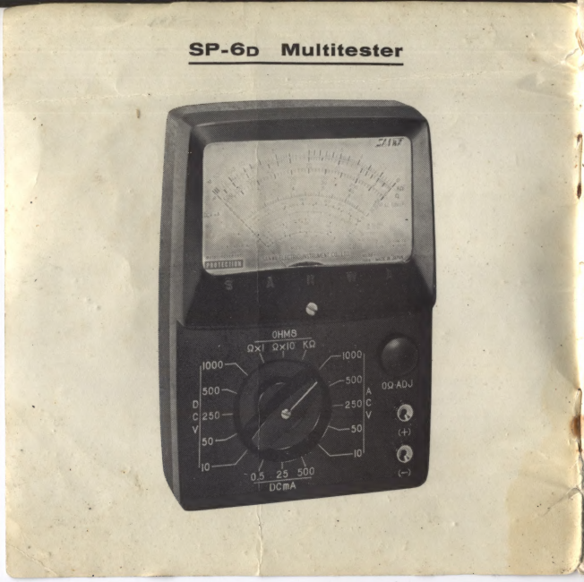
1.
Introduction.
Built
of
choice
materials
and
for
its
dependable
perfor-
mance,
the
§P-6p
Multitester
assures
you
of
unfailing
electrical
engineering
service.
Functional
design
of
the
SP-6p
renders
it
a
standard
pocket-size
circuit
tester
of
rotary
switching
system
containing
the
following
features:
a.
The
meter
movement
is
doubly
protected
from
_
damage.
The
protection
circuit
electrically
safeguards
the’
movement
against
accidental
overcurrent,
and
mechanically
the
moving
element
is
supported
by
spring-backed
jewel
bearings
to
absorb
shock.
»
oS
me

b.
The
low
resistance
range
measures
0,2
ohm
at
minimum.
c.
The
wide
scale
dial
admits
full
light
for
easy
reading.
|
d.
Ranges
are
readily
selected
by
a
single-control
rotary
switch.
e.
The
battery
sheaths
eliminate
reading
error
for
all
types
of
cells,
magnetic
or
nonmagnetic
armoured.
An
electric
circuit
tester
is
a
precision
instrument.
To
avoid
misuse,
read
this
booklet
carefully
before
you
Operate
your
meter.
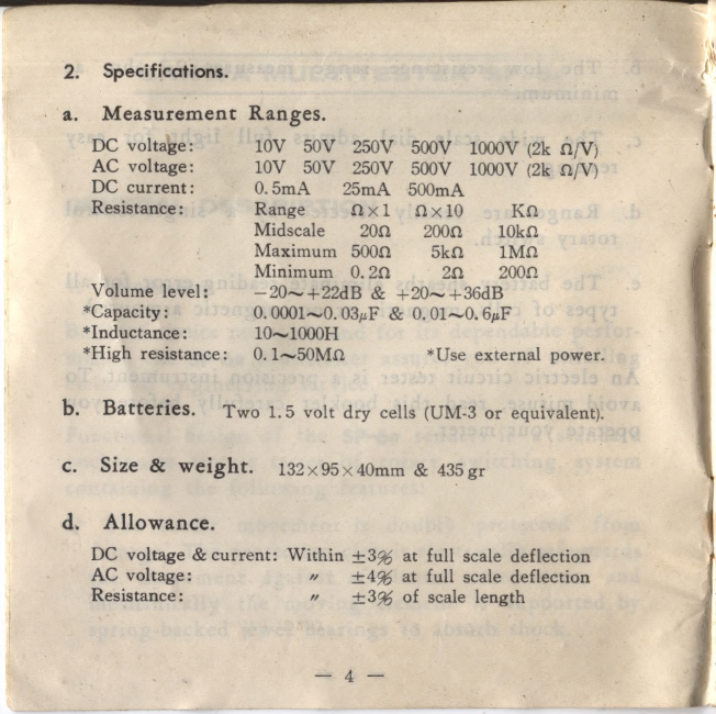
2.
Specifications.
:
|
|
j
x
a.
Measurement
Ranges.
DC
voltage:
10V
50V
250V
500V
1000V
(2k
a/V)
_
AC
voltage:
10V
SOV
250V
500V_
1000V
(2k
2/V)
DC
current:
0.5mA
25mA
500mA
Resistance:
Range
Qx1
2x10
KQ
Midscale
202
2002
10ka
Maximum
5000
5ka
1MQ
Minimum
0.20
20,
2002
Volume
level:
—20~+22dB
&
+20~+36dB
*Capacity
:
0.
0001~0.
03uF
&
0.01~0.
6yF
*Inductance:
10~1000H
*High
resistance:
0.1~50M0Q
*Use
external
power.
b.
Batteries.
Two
1.5
volt
dry
cells
(UM-3
or
equivalent).
c.
Size
&
weight.
132x95x40mm
&
435
¢r
d.
Allowance.
DC
voltage
&
current:
Within
+3
at
full
scale
deflection
AC
voltage:
vw
+49%
at
full
scale
deflection
Resistance:
vw
+39%
of
scale
length

GENERAL
MAINTENANCE
.
‘
Before
applying
the
test
leads
to
a
circuit,
always
confirm
the
range
to
be
used.
Misapplication
of
an
ohm
or
current
range
for
a
voltage
measurement
will
burn
a
shunt,
resistor
or
the
rectifier
rendering
the
meter
out
of
use.
For
accurate
measurements
of
voltage
and
current,
choose
a
range
which
will
allow
the
pointer
to
fall
within
the
right
hand
half
of
the
scale.
For
instance,
1.5
and
9
volt
batteries
should
be
checked
on
the
DC
10
volt
range,
while
the
power
distribution
line
of
220
volts,
on
the
AC
250
volt
range.
Less
accu-
rate
are
the
readings
on
the
left
hand
half.
When
checking
an
unknown
voltage
or
current,
always
start
with
the
highest
range
to
safeguard
the
meter
movement
from.
getting
overloaded.
After
the
first
reading,
the
switch
can
be
reset
to
a
lower
range
for
a
more
accurate
reading.
—
5
—
Aer
.
2
He
ts
sy
a
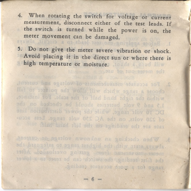
4.
When
rotating
the
switch
for
voltage
or
cutrent
|
measurement,
disconnect
either
of
the
test
leads.
If
the
switch
is
turned
while
the
power
is
on,
the
meter
movement
can
be
damaged,
5.
Do
not
give
the
meter
severe
vibration
ot
shock.
Avoid
placing
it
in
the
direct
sun
or
where
there
is
high
temperature
or
moisture.
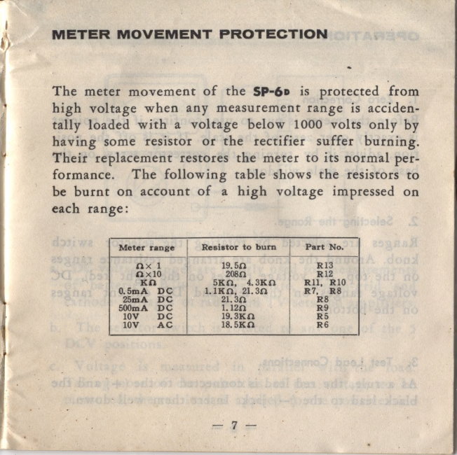
METER
MOVEMENT
PROTECTION
am
The
meter
movement
of
the
$P-6p
is
protected
from
high
voltage
when
any
measurement
range
is
acciden-
tally
loaded
with
a
voltage
below
1000
volts
only
by
having
some
resistor
or
the
rectifier
suffer
burning.
Their
replacement
restores
the
meter
to
its
normal
per-
formance.
The
following
table
shows
the
resistors
to
be
burnt
on
account
of
a
high
voltage
impressed
on
each
range:
|
Meter
range
Resistor
to
burn
Part
No.
ax
i
19.50
RI3
ax10
2082
R12
Ka
5KQ,
4.3K2
Rll,
R10
0.5mA
DC
11KQ,
21.30
R7,
R8
2mA
DC
21.32
R8
500mA
DC
1.120
RY
10V
DC
19.3KQ
R5
10V
AC
18.5KQ
R6
OPERATION
--:—
3
|
[Yo
See
5
pisioker
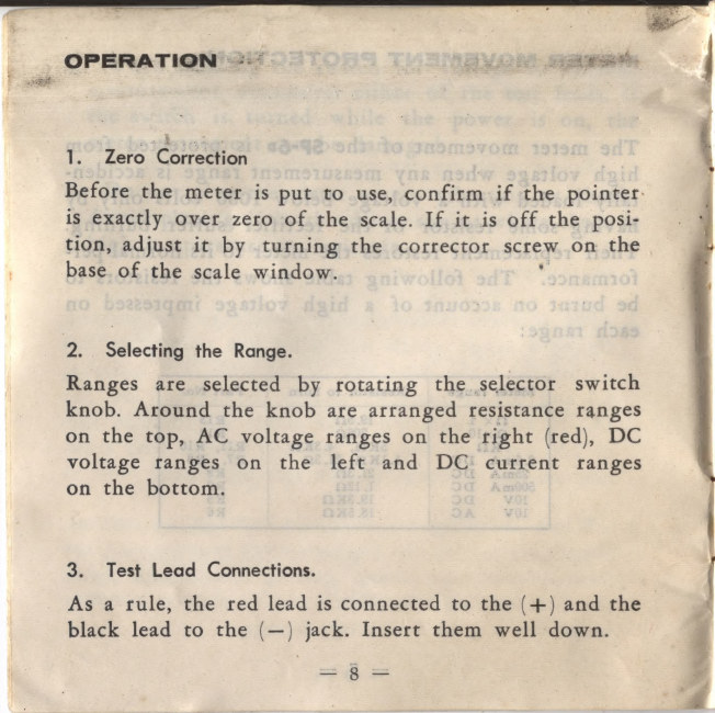
1.
Zero
Correction
Before
the
meter
is
put
to
use,
confirm
if
the
pointer.
is
exactly
over
zero
of
the
scale.
If
it
is
off
the
posi-
tion,
adjust
it
by
turning
the
corrector
screw
on
the
base
of
the
scale
window.
-
Selectiig
the
Range.
Ranges
are
selected
by
rotating
the
selector
eed
knob.
Around
the
knob
are
arranged
resistance
a
on
the
top,
AC
voltage
ranges
on
the
right
(red),
D
voltage
ranges
on
the
left
and
DC
current
ae
on
the
bottom.
3.
Test
Lead
Connections.
As
a
tule,
the
red
lead
is
connected
to
the
(+)
and
the
-
black
lead
to
the
(—)
jack.
Insert
them
well
down.
=
3
=
-
ee
ee
an
ae
Power
he
ee,
|
“A:
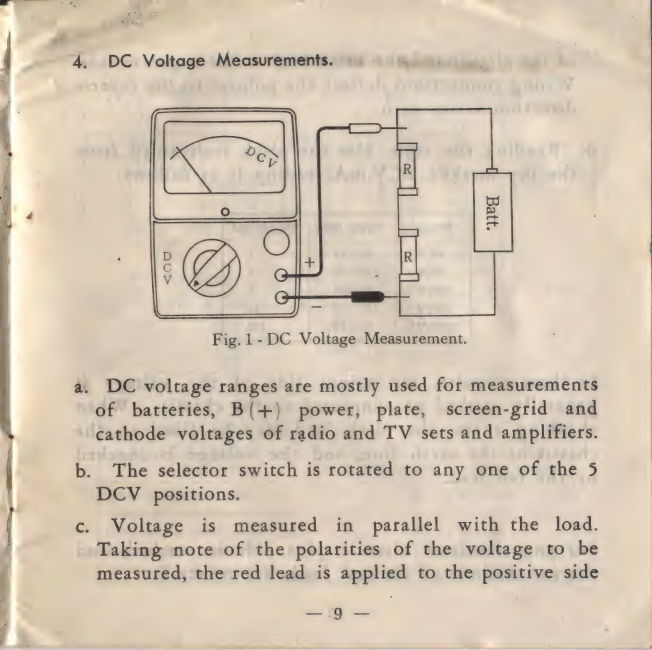
DE
Voltage
Measurements.
=
=
-
Fig.
1-DC
Voltage
Measurement.
a.
DC
voltage
ranges
are
mostly
used
for
measurements
of
batteries,
B(+)
power,
plate,
screen-grid
and
cathode
voltages
of
radio
and
TV
sets
and
amplifiers.
b.
The
selector
switch
is
rotated
to
any
one
of
the
5
DCV
positions.
c.
Voltage
is
measured
in
parallel
with
the
load.
Taking
note
of
the
polarities
of
the
voltage
to
be
-measured,
the
red
lead
is
applied
to
the
positive:
side
—
G9
—

Tr
ancients.
Ns
=
ge
RO
a
aii.
wi
of
the
circuit
and
the
black
lead
to
the
negative
side.
A
Wrong
connections
deflect
the
pointer
to
the
reverse
direction
across
zero.
j
d.
Reading
the
scale.
Use
the
black
scale
third
from
the
top
marked
DCV.mA
reading
it
as
follows:
Range
|
Scale
line
|
Multiplied
'
10(V)
0—
10
1
50(V)
0—
50
1
250(V)
0—250
1
500(V)
0—
50
10
1000(V)
0—
10
100
In
these
circuits,
the
minus
side
of
the
voltage
is
generally
earthed
or
connected
to
the
chassis.
When
checking
them,
the
black
lead
may
be
fixed
to
the
chassis
or
the
earth
line,
and
the
voltage
is
checked
by
the
red
lead.
For
pnp
transistor
circuits,
plus
side
is
earthed,
and
the
connections
of
the
test
leads
are
reversed.
or
Ls.
my
CTS
area
.
ee
ep
7
N
ev
7
7
(Vs)
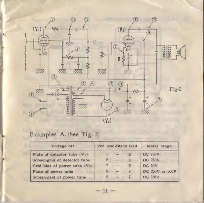
Examples
A.
(See
Fig.
2)
Voltage
of:
|
Red
lead-Black
lead
|
Meter
range
Plate
of
detector
tube
(V1)
5
—
E
DC
250V
Screen-grid
of
detector
tube
6
—
E
DC
250V
Grid
bias
of
power
tube
(V2)
7.
—
E
DC
50V
Plate
of
power
tube
8
aa
7
DC
250V
or
500V
9
a
7
DC
250V
Screen-grid
of
power
tube
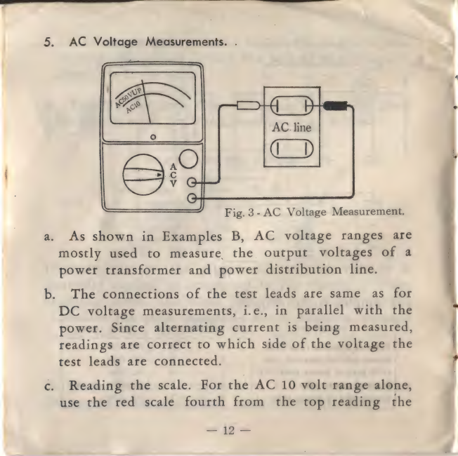
5.
AC
Voltage
Measurements.
.
a.
Fig.
3-
AC
Voltage
Measurement.
As
shown
in
Examples
B,
AC
voltage
ranges
are
mostly
used
to
measure
the
output
voltages
of
a
power
transformer
and
power
distribution
line.
b.
The
connections
of
the
test
leads
are
same
as
for
¢:
DC
voltage
measurements,
i.e.,
in
parallel
with
the
power.
Since
alternating
current
is
being
measured,
readings
are
correct
to
which
side
of
the
voltage
the
test
leads
are
connected.
|
Reading
the
scale.
For
the
AC
10
volt
range
alone,
use
the
red
scale
fourth
from
the
top
reading
the
é
figures
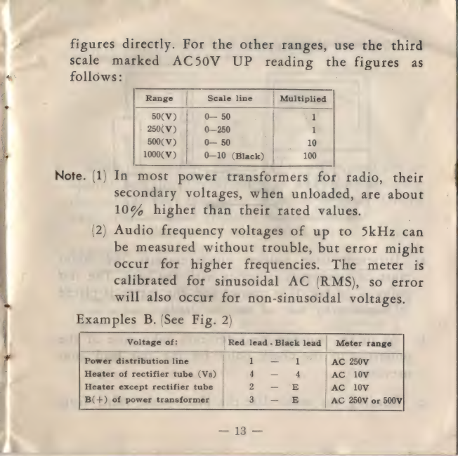
directly.
For
the
other
ranges,
use
the
chit
scale
marked
ACS50V
UP
reading
the
figures
as
4
follows:
Range
|
-
Seale
line
sacar)
-
50(V)
0—
50
1
-
250(V)
0—250
500(V)
oO—
50
oo
a
1000('V
)
0—10
(Black)
100
Note.
(1)
In
most
power
transformers
for
radio,
their
secondary
voltages,
when
unloaded,
are
about
10%
higher
than
their
rated
values.
(2)
Audio
frequency
voltages
of
up
to
5kHz
can
be
measured
without
trouble,
but
error
might
occur
for
higher
frequencies.
The
meter
is
calibrated
for
sinusoidal
AC
(RMS),
so
error
will
also
occur
for
non-sinusoidal
voltages.
Examples
B.
(See
Fig.
2)
Voltage
of:
|
Red
lead.
Black
lead
|
Meter
range
1
1
AC
250V
Heater
of
rectifier
tube
(Vs)
4
4
AC
10V
Heater
except
rectifier
tube
2
—
E
AC
10V
B(+)
of
power
transformer
3
E
AC
250V
or
500V
r
Powér
distribution
line
|

6.
DC
Current
Measurements.
~~
Poy
Fig.
4-
DC
Current
Measurement.
a.
Different
from
voltage’
measurememts,
the
meter
must
be
connected
in
series
with
the
load.
The
test
point
(x
in
Fig.
1)
is
opened
and
the
meter
is
placed
in
between
by
way
of
the
test
leads.
b.
As
in
DC
voltage
measurements,
take
note
of
the
polarities
of
the
check
point
for
the
test
lead
con-
nections.
|
c.
Reading
the
scale.
Use
the
black
scale
third
from
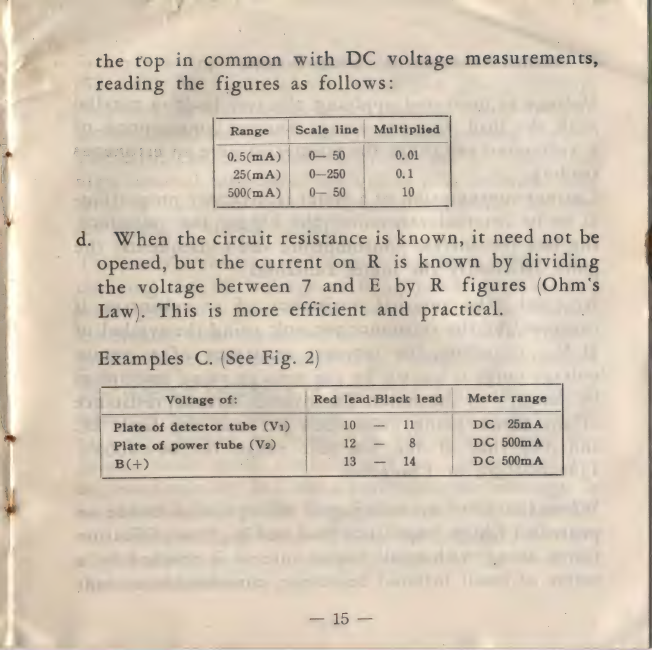
_
~~
the
top
in
common
with
DC
voltage
measurements,
reading
the
figures
as
follows:
Range
|
Scale
line
|
Multiplied
*
0.5(mA)|
0}
50
|
0.01
f
25(mA)
|
0-250
0.1
500(mA)
|
0—
50
10
d.
When
the
circuit
resistance
is
known,
it
need
not
be
opened,
but
the
current
on
R
is
known
by
dividing
the
voltage
between
7
and
E
by
R
figures
(Ohm's
;
Law).
This
is
more
efficient
and
practical.
:
Examples
C.
(See
Fig.
2)
Voltage
of:
|
Red
lead-Black
lead
|
Meter
range
Plate
of
detector
tube
(V1)
|
wOLSt'*
11
DC
2%mA
Plate
of
power
tube
(V2)
12
—
8
DC
500mA
B(+)
13
—
14
DC
500mA

7.
Internal
Resistance
of
Voltage
Ranges.
Voltage
is
measured
applying
the
test
leads
in
parallel
with
the
load.
Current
energy
(current
consumption
of.
a
voltmeter)
can
cause
the
pointer
to
give
an
erroneous
reading.
Current
consumption
of
a
meter
is
inversely
proportion-
al
to
its
internal
resistance:
the
bigger
the
resistance,
the
less
the
current
consumption,
and
pers
aa
eh
the
more
efficiently
the
meter
functions.
As
a
rule,
the
internal
resistance
of
a
voltmeter
is
expressed
by
the
resistance
per
volt
using
the
symbol
of
Q/V.
Therefore,
the
internal
resistance
of
a
certain
voltage
range
is
known
by
the
voltage
value
multiplied
by
the
Q/V
of
the
meter.
The
overall
internal
resistance
of
the
SP-6p
being
2000
ohms
pet
volt
for
both
DC
and
AC,
that
of
the
500
volt
range
is
500
2000=
1,000,000
(Q),
or
1
megohm.
When
the
plate
or
screen-grid
voltage
of
a
triode
or
pentode
of
high
impedance
load
and
high
amplification
factor
along
with
small
circuit
current
is
checked
by
a
meter
of
small
internal
resistance,
considerable
current
-
Whi
i
so

oe
ae
EL
Sie
flows
from
the
meter
into
the
series
load
resistance
of
the
tube.
As
a
consequence,
there
is
a
greater
voltage
drop
and
the
meter
reads
lower
than
the
true
value:
the
connection
of
the
meter
upsets
the
circuit
being
checked.
The
error
can
be
minimized
by
the
use
of
a
meter
of
high
internal
resistance,
but
unless
it
is
infinite,
some
error
is
inevitable
even
if
a
valve
voltmeter
be
used
for
checking
such
a
circuit.
The
internal
resistance
of
a
meter
has
little
effect
when
checking
the
DC
voltage
of
B(+)
power
or
plate
and
screen-grid
of a
power
tube
because
their
impedances
are
smaller
than
the
meter
impedance:
it
is
the
control
grid
voltage
that
is
disturbed
by
voltage
measurement.
The
internal
resistance
of
a
voltage
range,
is
propor-
tionately
bigger
for
higher
voltages
and
readings
are
naturally
higher
on
them.
On
the
other
hand,
the
pointer
tends
more
towards
left
on
account
of
the
decreased
current,
and
less
accurate
are
the
readings.
In
consideration
of
it,
the
voltage
values
of
radio
and
TV
sets
are
usually
given
specifying
the
internal
resistance
of
the
meter
and
its
voltage
ranges
to
be
used
for
their
measurements.

8.
Resistance
Measurements.
a.
The
selector
switch
can
be
rotated
to
any
one
of
the
3
résistance
ranges.
Q
x1
is
for
measurements
of
0-50
ohms,
Q
«10
for
50-2k
ohms,
and
KQ
for
2k-1M
ohms.
For
an
accurate
measurement,
use
a
range
which
will
allow
the
pointer
to
fall
near
the
middle
of,
the
ohm
scale.
Fig.
5-
Resistance
Measurement.
(Zero
ohm
adjustment)
—
i
ei
ee
Se
ae
=
=
SE
AS
=e
ag
2h,
Other Sanwa Test Equipment manuals


