manuals.online logo
Brands
  1. Home
  2. •
  3. Brands
  4. •
  5. Sanyo
  6. •
  7. Air Conditioner
  8. •
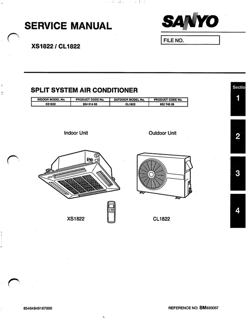
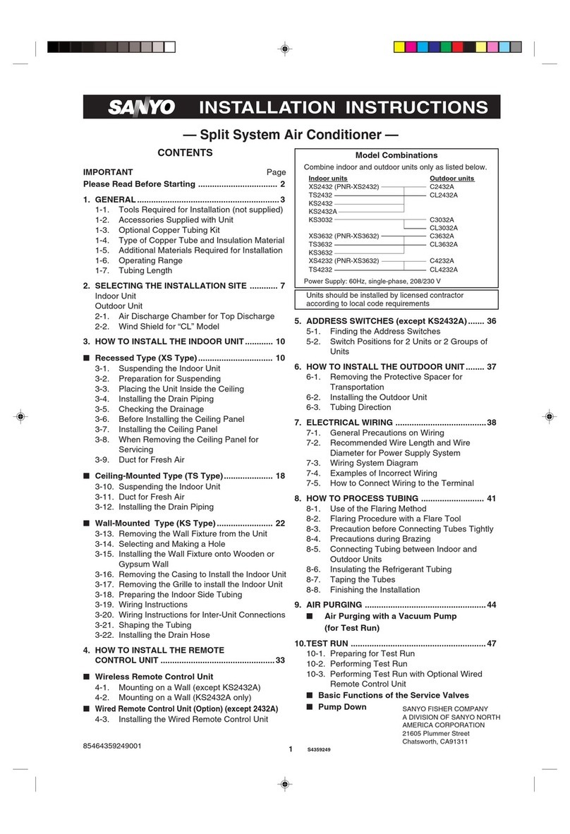
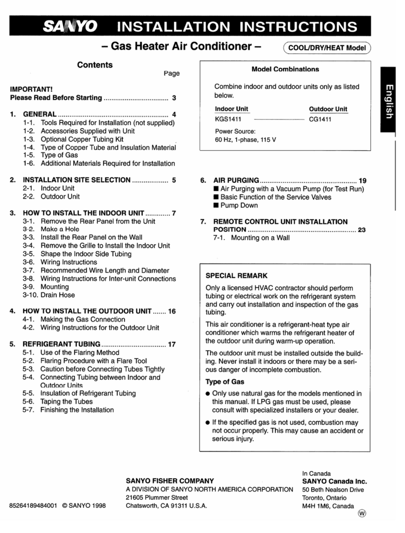
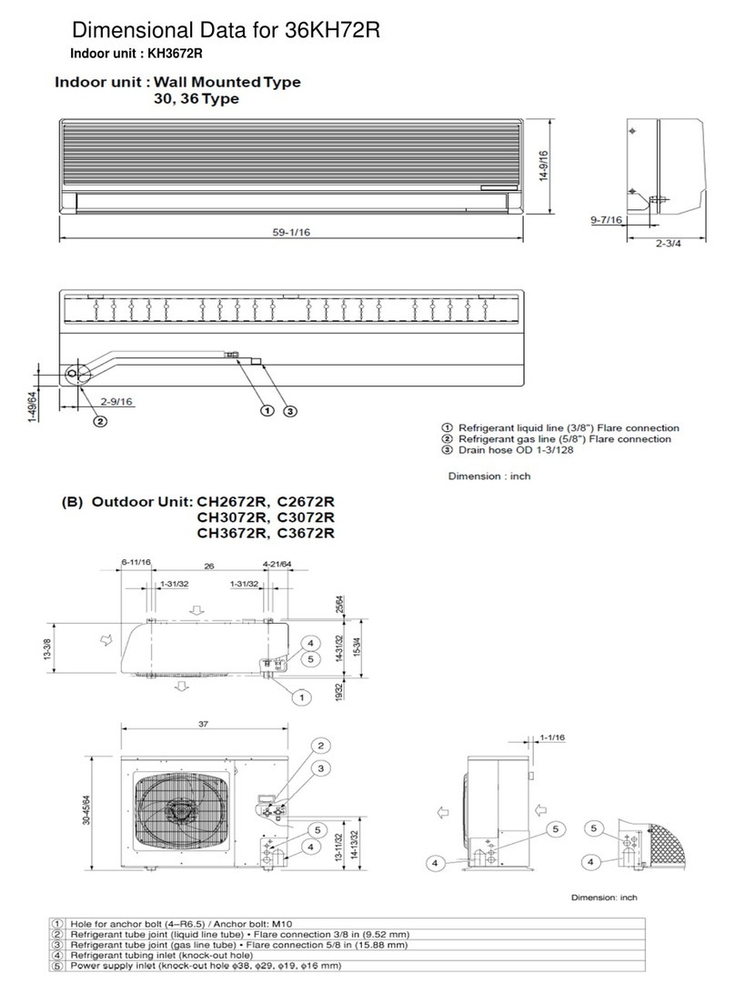
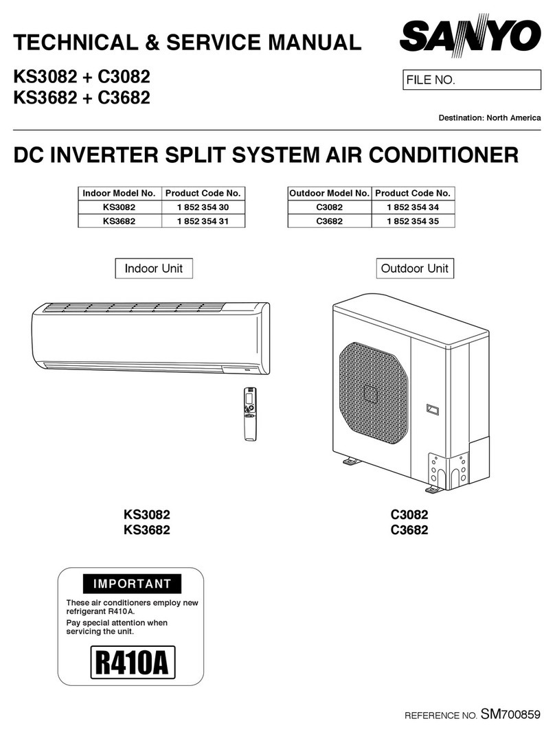
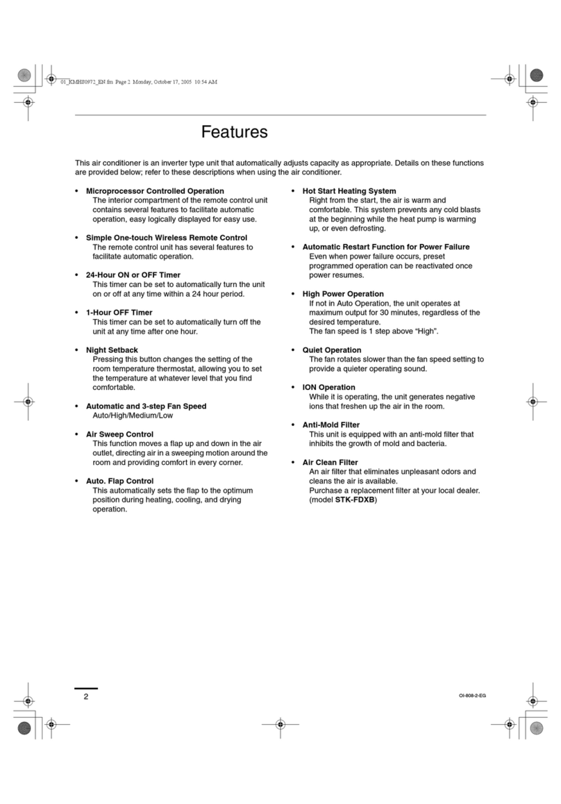
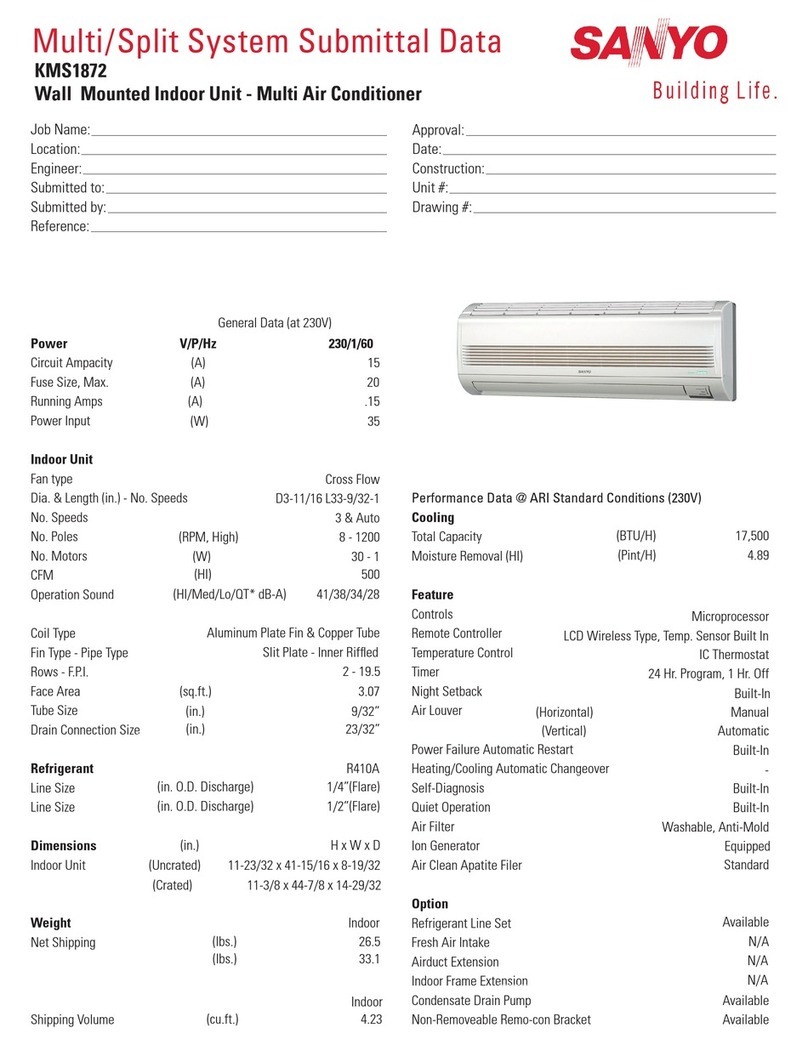
  9. Sanyo ECO-i CHDZR07263 Series User manual

Sanyo ECO-i CHDZR07263 Series User manual

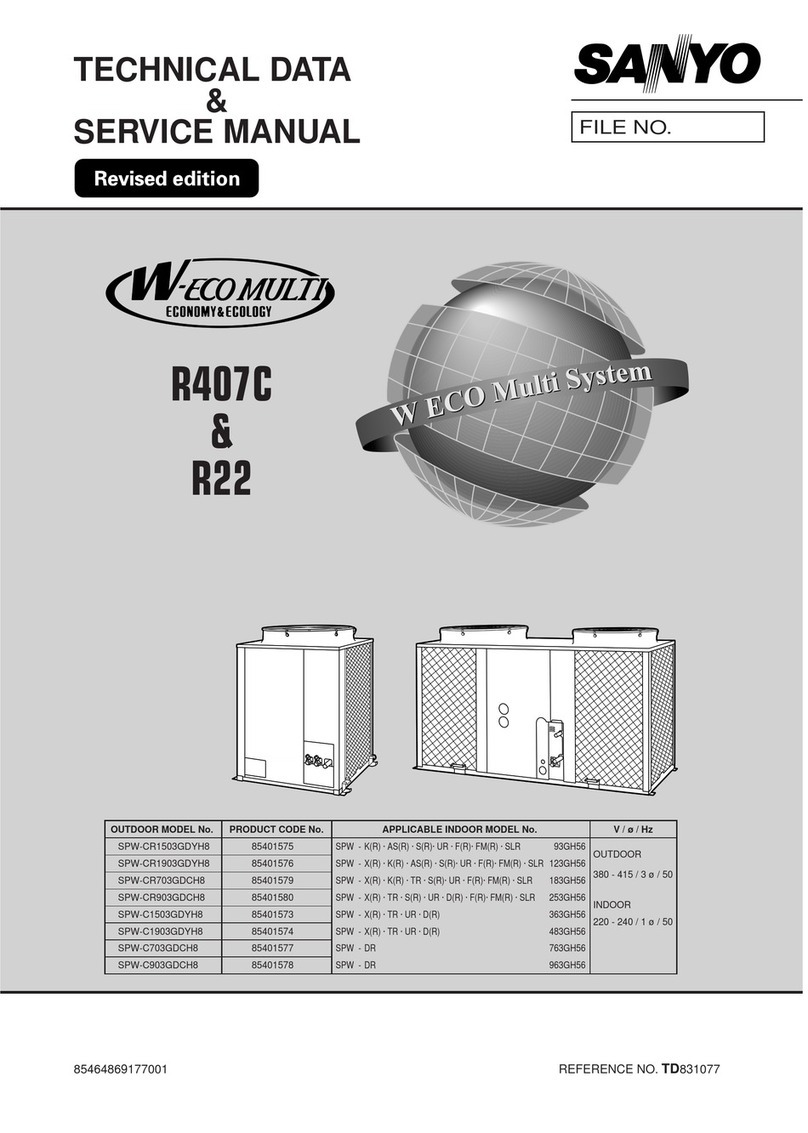
Outdoor Units
Refrigerant R410A is used in the outdoor units.
9672Class
C
ECO-i W-3WAY CHDZ07263
CHDZ09663
CHDZR07263
CHDZR09663
85464849281000 REFERENCE NO. SM830181-00
Indoor Units
Class 9 12 15 18 2419 36 5448
UM Slim Concealed
Duct Type UMHX0762 UMHX1262UMHX0962 UMHX1562 UMHX1862
XM 4-Way Air Discharge
Mini Semi-Concealed XMHX1252 XMHX1852
U Concealed Duct Type UHX0762 UHX1262UHX0962 UHX1562 UHX1862 UHX2462 UHX3662 UHX4862 UHX5462
X4-Way Air Discharge
Semi-Concealed XHX1252 XHX1852 XHX2452 XHX3652
A1-Way Air Discharge
Semi-Concealed AHX0752 AHX1252AHX0952
T Ceiling-Mounted THX1252 THX1852 THX2452
DConcealed-Duct High
Static Pressure DHX3652 DHX4852
FHX0762 FHX1262FHX0962 FHX1562 FHX1862 FHX2462F
FMHX0762 FMHX1262
FMHX0962 FMHX1562 FMHX1862 FMHX2462
FM Concealed-Floor
Standing Type
KHX0752 KHX1252KHX0952K KHX1862 KHX1962**
**
KHX2452
7
3-WAY ECO-i
MULTI SYSTEM
CHDZ07263
CHDZ09663
CHDZR07263
CHDZR09663
*
*
* Salt-Air Damage Resistant Specifications.
** Necessary to install the External Electronic Expansion Valve Kit (Optional:ATK-SVRK56BA).
SERVICE MANUAL
Wall-Mounted Type
Floor-Standing Type
SM83018100.indbaSM83018100.indba 2010/03/0119:23:242010/03/0119:23:24
i
Please Read Before Starting
This air conditioning system meets strict safety and operat-
ing standards. As the installer or service person, it is an
important part of your job to install or service the system so
it operates safely and efficiently.
Carefully read this instruction booklet before beginning.
Follow each installation or repair step exactly as shown.
Observe all local, state, and national electrical codes.
This symbol refers to a hazard or
unsafe practice which can result
in personal injury or product or
property damage.
In Case of Improper Installation
When Wiring
ELECTRICAL SHOCK CAN CAUS
SEVERE PERSONAL INJURY OR DEATH.
ONLY A QUALIFIED, EXPERIENCED
ELECTRICIAN SHOULD ATTEMPT TO
WIRE THIS SYSTEM.
E
• Do not supply power to the unit until all wiring and tubing
are completed or reconnected and checked.
• Highly dangerous electrical voltages are used in this sys-
tem. Carefully refer to the wiring diagram and these
instructions when wiring. Improper connections and inad-
equate grounding can cause accidental injury or death.
•
When Installing…
…In a Room
Properly insulate any tubing run inside a room to preven
“sweating” that can cause dripping and water damage to
walls and floors.
t
…In Moist or Uneven Locations
…
…In a Snowy Area (for Heat Pump-type Systems)
Install the outdoor unit on a raised platform that is higher
than drifting snow. Provide snow vents.
•
• Keep all tubing runs as short as possible.
• Use the flare method for connecting tubing.
• Apply refrigerant lubricant to the matching surfaces of
the flare and union tubes before connecting them, then
tighten the nut with a torque wrench for a leak-free con-
nection.
• Check carefully for leaks before starting the test run.
When Servicing
•
• Keep your fingers and clothing away from any moving
parts.
•
•
• Confirm after installation that no refrigerant gas is leak-
ing. If the gas comes in contact with a burning stove,
gas water heater, electric room heater or other heat
source, it can cause the generation of poisonous gas.
IMPORTANT!
For safe installation and trouble-free operation, you must:
Pay close attention to all warning and caution notices
given in this manual.
This symbol refers to a hazard or
unsafe practice which can result
in severe personal injury or death.
WARNING
CAUTION
If Necessary, Get Help
These instructions are all you need for most installation
sites and maintenance conditions. If you require help for a
special problem, contact our sales/service outlet or your
certified dealer for additional instructions.
The manufacturer shall in no way be responsible for
improper installation or maintenance service, including fail-
ure to follow the instructions in this document.
SPECIAL PRECAUTIONS
WARNING
Ground the unit following local electrical codes.
Connect all wiring tightly. Loose wiring may cause over-
heating at connection points and a possible fire hazard.
When Transporting
Be careful when picking up and moving the indoor and outdoor
units. Get a partner to help, and bend your knees when lifting
to reduce strain on your back. Sharp edges or thin aluminum
fins on the air conditioner can cut your fingers.
Use a raised concrete pad or concrete blocks to provide a
solid, level foundation for the outdoor unit. This prevents
water damage and abnormal vibration.
In an Area with High Winds
Securely anchor the outdoor unit down with bolts and a
metal frame. Provide a suitable air baffle.
When Connecting Refrigerant Tubing
Ventilate the room well, in the event that is refrigerant
gas leaks during the installation. Be careful not to allow
contact of the refrigerant gas with a flame as this will
cause the generation of poisonous gas.
Turn the power OFF at the main power box (mains)
before opening the unit to check or repair electrical parts
and wiring.
Clean up the site after you finish, remembering to check
that no metal scraps or bits of wiring have been left
inside the unit being serviced.
CAUTION
Ventilate any enclosed areas when installing or testing
the refrigeration system. Escaped refrigerant gas, on
contact with fire or heat, can produce dangerously toxic
gas.
•
•
•
•
•
SM83018100.indbbSM83018100.indbb 2010/03/0119:23:252010/03/0119:23:25
ii
Check of Density Limit
The room in which the air conditioner is to be
installed requires a design that in the event of refrig-
erant gas leaking out, its density will not exceed a set
limit.
The refrigerant (R410A), which is used in the aircondition-
er, is safe, without the toxicity or combustibility of ammonia,
and is not restricted by laws imposed to protect the ozone
layer. However, since it contains more than air, it poses the
risk of suffocation if its density should rise excessively. Suf-
focation from leakage of refrigerant is almost non-existent.
With the recent increase in the number of high density
buildings, however, the installation of multi air conditioner
systems is on the increase because of the need for effec-
tive use off loor space, individual control, energy conserva-
tion by curtailing heat and carrying power, etc.
Most importantly, the multi air conditioner system is able
to replenish a large amount of refrigerant compared to
conventional individual air conditioners. If a single unit of
the multi air conditioner system is to be installed in a
small room, select a suitable model and installation pro-
cedure so that if the refrigerant accidentally leaks out, its
density does not reach the limit (and in the event of an
emergency, measures can be made before injury can
occur).
ASHRAE and the International Mechanical Code of the
ICC as well as CSA provide guidance and define safe-
guards related to the use of refrigerants, all of which define
a Refrigerant Concentration Level (RCL) of 25 pounds
per 1,000 cubic feet for R410A refrigerant.
For additional guidance and precautions related to
refrigerant safety, please refer to the following documents:
International Mechanical Code 2009 (IMC-2009)
(or more recently revised)
ASHRAE 15
ASHRAE 34
SM83018100.indbcSM83018100.indbc 2010/03/0119:23:252010/03/0119:23:25
—
CONTENTS
—
Section 1: CONTROL FUNCTIONS. . . . . . . . . . . . . . . . . . . . . . . . . . . . . . . . . . . . . . . . . . 1-1
1. Introduction . . . . . . . . . . . . . . . . . . . . . . . . . . . . . . . . . . . . . . . . . . . . . . . . . . . . . . . . . . . . . 1-2
2. Selecting Outdoor Unit for Operation . . . . . . . . . . . . . . . . . . . . . . . . . . . . . . . . . . . . . . . . . 1-3
3. Compressor Control . . . . . . . . . . . . . . . . . . . . . . . . . . . . . . . . . . . . . . . . . . . . . . . . . . . . . . 1-4
4. Special Controls . . . . . . . . . . . . . . . . . . . . . . . . . . . . . . . . . . . . . . . . . . . . . . . . . . . . . . . . 1-11
5. Other Controls . . . . . . . . . . . . . . . . . . . . . . . . . . . . . . . . . . . . . . . . . . . . . . . . . . . . . . . . . . 1-16
6. Operation of Solenoid Valves . . . . . . . . . . . . . . . . . . . . . . . . . . . . . . . . . . . . . . . . . . . . . . 1-17
7. Outdoor Unit Electronic Control Valves [MOV1, MOV2, MOV4] . . . . . . . . . . . . . . . . . . . . 1-19
8. Outdoor Fan Control . . . . . . . . . . . . . . . . . . . . . . . . . . . . . . . . . . . . . . . . . . . . . . . . . . . . . 1-21
9. Demand Control . . . . . . . . . . . . . . . . . . . . . . . . . . . . . . . . . . . . . . . . . . . . . . . . . . . . . . . . 1-22
10. Indoor Unit Control of the Electronic Control Valve . . . . . . . . . . . . . . . . . . . . . . . . . . . . . . 1-23
11. Solenoid Valve Kit Control . . . . . . . . . . . . . . . . . . . . . . . . . . . . . . . . . . . . . . . . . . . . . . . . . 1-25
12. Indoor Special Control . . . . . . . . . . . . . . . . . . . . . . . . . . . . . . . . . . . . . . . . . . . . . . . . . . . 1-26
13. Discharge Temperature . . . . . . . . . . . . . . . . . . . . . . . . . . . . . . . . . . . . . . . . . . . . . . . . . . . 1-27
14. Current Protection . . . . . . . . . . . . . . . . . . . . . . . . . . . . . . . . . . . . . . . . . . . . . . . . . . . . . . . 1-28
15. Low Oil Alarm . . . . . . . . . . . . . . . . . . . . . . . . . . . . . . . . . . . . . . . . . . . . . . . . . . . . . . . . . . 1-29
16. Pressure Sensor Failure . . . . . . . . . . . . . . . . . . . . . . . . . . . . . . . . . . . . . . . . . . . . . . . . . . 1-30
17. Backup Operation . . . . . . . . . . . . . . . . . . . . . . . . . . . . . . . . . . . . . . . . . . . . . . . . . . . . . . . 1-31
18. Service Maintenance Functions . . . . . . . . . . . . . . . . . . . . . . . . . . . . . . . . . . . . . . . . . . . . 1-33
19. Other Functions . . . . . . . . . . . . . . . . . . . . . . . . . . . . . . . . . . . . . . . . . . . . . . . . . . . . . . . . 1-36
Section 2: OUTDOOR UNIT REPAIR PROCEDURES . . . . . . . . . . . . . . . . . . . . . . . . . . . 2-1
1. Removing Panels . . . . . . . . . . . . . . . . . . . . . . . . . . . . . . . . . . . . . . . . . . . . . . . . . . . . . . . . 2-2
2. Removing Electrical Component Box and Duct . . . . . . . . . . . . . . . . . . . . . . . . . . . . . . . . . 2-3
3. Discharging Compressor Oil . . . . . . . . . . . . . . . . . . . . . . . . . . . . . . . . . . . . . . . . . . . . . . . . 2-5
4. Backup Operation . . . . . . . . . . . . . . . . . . . . . . . . . . . . . . . . . . . . . . . . . . . . . . . . . . . . . . . . 2-6
5. Recovering Refrigerant . . . . . . . . . . . . . . . . . . . . . . . . . . . . . . . . . . . . . . . . . . . . . . . . . . . . 2-9
6. Checking for Leakage After Repair . . . . . . . . . . . . . . . . . . . . . . . . . . . . . . . . . . . . . . . . . . 2-14
7. Evacuating System . . . . . . . . . . . . . . . . . . . . . . . . . . . . . . . . . . . . . . . . . . . . . . . . . . . . . . 2-15
8. Charging Compressor Oil . . . . . . . . . . . . . . . . . . . . . . . . . . . . . . . . . . . . . . . . . . . . . . . . . 2-16
9. Pumping Out Refrigerant from Outdoor Unit . . . . . . . . . . . . . . . . . . . . . . . . . . . . . . . . . . . 2-20
10. Compressor . . . . . . . . . . . . . . . . . . . . . . . . . . . . . . . . . . . . . . . . . . . . . . . . . . . . . . . . . . . 2-23
11. High and Low Pressure Sensors . . . . . . . . . . . . . . . . . . . . . . . . . . . . . . . . . . . . . . . . . . . 2-35
12. Replacing 4-way valve . . . . . . . . . . . . . . . . . . . . . . . . . . . . . . . . . . . . . . . . . . . . . . . . . . . 2-36
Section 3. OUTDOOR UNIT MAINTENANCE REMOTE CONTROLLER . . . . . . . . . . . . 3-1
1. Overview . . . . . . . . . . . . . . . . . . . . . . . . . . . . . . . . . . . . . . . . . . . . . . . . . . . . . . . . . . . . . . . 3-2
2. Functions . . . . . . . . . . . . . . . . . . . . . . . . . . . . . . . . . . . . . . . . . . . . . . . . . . . . . . . . . . . . . . . 3-3
3. Ordinary Display Controls and Functions . . . . . . . . . . . . . . . . . . . . . . . . . . . . . . . . . . . . . . 3-4
4. Monitoring Operations . . . . . . . . . . . . . . . . . . . . . . . . . . . . . . . . . . . . . . . . . . . . . . . . . . . . . 3-9
5. Outdoor Unit Alarm History Monitor . . . . . . . . . . . . . . . . . . . . . . . . . . . . . . . . . . . . . . . . . 3-11
6. Mode Settings . . . . . . . . . . . . . . . . . . . . . . . . . . . . . . . . . . . . . . . . . . . . . . . . . . . . . . . . . . 3-12
iii
SM83018100.indbiiSM83018100.indbii 2010/03/0119:23:252010/03/0119:23:25
Section 4. REMOTE CONTROLLER FUNCTIONS . . . . . . . . . . . . . . . . . . . . . . . . . . . . . 4-1
1. Simple Settings Function . . . . . . . . . . . . . . . . . . . . . . . . . . . . . . . . . . . . . . . . . . . . . . . . . . . 4-2
2. Detailed Settings Function. . . . . . . . . . . . . . . . . . . . . . . . . . . . . . . . . . . . . . . . . . . . . . . . . . 4-4
3. Remote Controller Servicing Functions . . . . . . . . . . . . . . . . . . . . . . . . . . . . . . . . . . . . . . . 4-15
Section 5. TROUBLE DIAGNOSIS . . . . . . . . . . . . . . . . . . . . . . . . . . . . . . . . . . . . . . . . . . 5-1
1. Contents of Remote Controller Switch Alarm Display . . . . . . . . . . . . . . . . . . . . . . . . . . . . . 5-2
2. Outdoor Unit Control Panel LED Display . . . . . . . . . . . . . . . . . . . . . . . . . . . . . . . . . . . . . . 5-4
3. Remote Controller Servicing Functions . . . . . . . . . . . . . . . . . . . . . . . . . . . . . . . . . . . . . . . 5-5
4. 3-WAY ECO-i Alarm Codes . . . . . . . . . . . . . . . . . . . . . . . . . . . . . . . . . . . . . . . . . . . . . . . . . 5-7
5. Blinking Inspection Display on the Remote Controller . . . . . . . . . . . . . . . . . . . . . . . . . . . 5-27
6. Inspection of Parts . . . . . . . . . . . . . . . . . . . . . . . . . . . . . . . . . . . . . . . . . . . . . . . . . . . . . . 5-28
7. Test Pin . . . . . . . . . . . . . . . . . . . . . . . . . . . . . . . . . . . . . . . . . . . . . . . . . . . . . . . . . . . . . . . 5-29
8. Thermister Characteristics Curve . . . . . . . . . . . . . . . . . . . . . . . . . . . . . . . . . . . . . . . . . . . 5-30
iv
SM83018100.indbiiiSM83018100.indbiii 2010/03/0119:23:252010/03/0119:23:25
1
1- 1
3-WAY ECO-i SYSTEM
Control Functions
Contents
1. CONTROL FUNCTIONS
1. Introduction . . . . . . . . . . . . . . . . . . . . . . . . . . . . . . . . . . . . . . . . . . . . . . . . . . . . . . . . . . . 1-2
2. Selecting Outdoor Unit for Operation . . . . . . . . . . . . . . . . . . . . . . . . . . . . . . . . . . . . . . 1-3
3. Compressor Control . . . . . . . . . . . . . . . . . . . . . . . . . . . . . . . . . . . . . . . . . . . . . . . . . . . . 1-4
4. Special Controls . . . . . . . . . . . . . . . . . . . . . . . . . . . . . . . . . . . . . . . . . . . . . . . . . . . . . . 1-11
5. Other Controls . . . . . . . . . . . . . . . . . . . . . . . . . . . . . . . . . . . . . . . . . . . . . . . . . . . . . . . 1-16
6. Operation of Solenoid Valves . . . . . . . . . . . . . . . . . . . . . . . . . . . . . . . . . . . . . . . . . . . 1-17
7. Outdoor Unit Electronic Control Valves [MOV1, MOV2, MOV4] . . . . . . . . . . . . . . . . 1-19
8. Outdoor Fan Control . . . . . . . . . . . . . . . . . . . . . . . . . . . . . . . . . . . . . . . . . . . . . . . . . . 1-21
9. Demand Control . . . . . . . . . . . . . . . . . . . . . . . . . . . . . . . . . . . . . . . . . . . . . . . . . . . . . . 1-22
10. Indoor Unit Control of the Electronic Control Valve . . . . . . . . . . . . . . . . . . . . . . . . . 1-23
11. Solenoid Valve Kit Control . . . . . . . . . . . . . . . . . . . . . . . . . . . . . . . . . . . . . . . . . . . . . . 1-25
12. Indoor Special Control . . . . . . . . . . . . . . . . . . . . . . . . . . . . . . . . . . . . . . . . . . . . . . . . . 1-26
13. Discharge Temperature . . . . . . . . . . . . . . . . . . . . . . . . . . . . . . . . . . . . . . . . . . . . . . . . 1-27
14. Current Protection . . . . . . . . . . . . . . . . . . . . . . . . . . . . . . . . . . . . . . . . . . . . . . . . . . . . 1-28
15. Low Oil Alarm . . . . . . . . . . . . . . . . . . . . . . . . . . . . . . . . . . . . . . . . . . . . . . . . . . . . . . . . 1-29
16. Pressure Sensor Failure . . . . . . . . . . . . . . . . . . . . . . . . . . . . . . . . . . . . . . . . . . . . . . . 1-30
17. Backup Operation . . . . . . . . . . . . . . . . . . . . . . . . . . . . . . . . . . . . . . . . . . . . . . . . . . . . . 1-31
18. Service Maintenance Functions. . . . . . . . . . . . . . . . . . . . . . . . . . . . . . . . . . . . . . . . . . 1-33
19. Other Functions . . . . . . . . . . . . . . . . . . . . . . . . . . . . . . . . . . . . . . . . . . . . . . . . . . . . . . 1-36
SM83018100.indb1SM83018100.indb1 2010/03/0119:23:252010/03/0119:23:25
1
1- 2
1. Introduction
3-WAY ECO-i SYSTEM
Control Functions
The 3-WAY ECO-i is a system that allows multiple outdoor units to be connected. The outdoor units all contain
inverter compressors, and the system does not utilize the sub units that were used in earlier systems.
The outdoor unit where the unit No. is set to “1” includes the CCU (command controller unit) functions that are used
to control the entire system. As a result, the system will not operate if no outdoor unit has been set as unit No. “1.”
Required settings for Test Run
Outdoor unit No. 1 Outdoor unit Nos. 2
At time of shipment On-site setting At time of shipment On-site setting
System address 1 System 1 ~ 30 1 Not necessary
No. of indoor units 1 1 ~ 40 units 1 Not necessary
No. of outdoor units 1 1 ~ 3 units 1 Not necessary
Unit No. 1 Unit No. 1 1 Unit Nos. 2
This system can be expanded to connect a maximum of 3 outdoor units. (The system maximum capacity is 24
Ton.)
The CCU functions are disabled at all units except the unit that is set as unit No. 1. Therefore no problems will
result even if the system address, No. of indoor units, and No. of outdoor units settings are made at the other units.
However, making these settings may be convenient for manual backup operation, as it eliminates the necessity of
making the settings again if unit No. 1 fails. (If unit No. 1 fails, and the power supply to it is interrupted, it will be nec-
essary to set a different unit as unit No. 1 in order to use manual backup operation.)
SM83018100.indb2SM83018100.indb2 2010/03/0119:23:252010/03/0119:23:25
1
1- 3
3-WAY ECO-i SYSTEM
Control Functions
2. Selecting an Outdoor Unit for Operation
2-1. Outdoor Unit Operating Rules
Because in this system all outdoor units contain an inverter compressor, ordinarily there is no absolute order of
priority for compressor operation. Therefore there is no order of priority for the outdoor units.
However, it is possible to operate the outdoor units in sequence, beginning with unit No. 1, by using the outdoor
unit maintenance remote controller to change the outdoor unit EEPROM settings.
* For information concerning EEPROM settings, refer to the field application functions.
2-2. Delayed Start of Outdoor Units
(1) Delayed start of outdoor units in the same system
If it is necessary to operate the compressors simultaneously at multiple outdoor units, each outdoor unit will
start, beginning with unit No. 1, after a delay of a number of seconds equivalent to the outdoor unit address.
The units do not start simultaneously.
This is in order to reduce the load on the power receiving equipment.
Outdoor unit
address 1
Outdoor unit
address 2
(2) Delayed start for each system
At the time of factory shipment, delayed start for each system is not set to occur. Therefore when systems are
linked and multiple systems are selected for start simultaneously by the central control device, all systems will
begin operating simultaneously. For this reason, a function is included to delay the start time for each system
address when systems are linked and multiple systems are selected for start by the central control device.
In order to enable this delay time, it must be set in the EEPROM for each system. Those systems where this
setting has been made will start after a delay according to their system addresses.
* For information concerning EEPROM settings, refer to the field application functions.
2-3. Outdoor Unit Stop Rules
(1) Simultaneous stop of multiple outdoor units
When all outdoor units, or multiple outdoor units, must stop, the units stop at the same time. However,
depending on the communications timing, a difference of approximately 10 seconds may occur.
(2) Stopping individual outdoor units
●The last unit to stop operating is the outdoor unit that contains the inverter compressor with the shortest
amount of operating time.
●If the indoor load decreases, and it becomes necessary to reduce the number of operating outdoor units, the
compressors are stopped individually, in sequence. When all compressors installed in an outdoor unit have
stopped, that outdoor unit also stops.
Starts after 1 second Starts after 2 seconds
SM83018100.indb3SM83018100.indb3 2010/03/0119:23:252010/03/0119:23:25
1
1- 4
3. Compressor Control
3-WAY ECO-i SYSTEM
Control Functions
3-1. Compressors Mounted in the Outdoor Units
[CHDZ07263, CHDZR07263, CHDZ09663, CHDZR09663]
Capacity 72 96
Installed
compressor
Compressor 1 Rotary DC Inverter DC Inverter
Compressor 2 Scroll
–
5 hp
Constant
speed INVINV
Compressor 2 Compressor 1Compressor 1
Type 96Type 72
3-2. Compressor Selection Rules
Because all outdoor units in this system contain an inverter compressor, ordinarily there is no absolute order of
priority for compressor operation.
(1) Normal compressor operation sequence (set at time of shipment)
At least one inverter compressor is always operating in order to make fine adjustments to the system
lower-limit capacity. When multiple outdoor units are connected, each unit contains an inverter compressor.
Therefore, the inverter which operates is the inverter with the shortest amount of operating time. After the first
inverter compressor has started, the remaining inverter compressors and constant-speed compressors start
operating in order of the compressors which have the shortest amount of operating time.
* Immediately after installation, all compressors have an operating time of zero. In this case, the compressors
start in the following sequence: Inverter compressor > Constant-speed compressor.
<Details>
The A/C units are selected with consideration for the maximum load. Therefore, in most cases the maximum
capacity is not required. Ordinarily, the operating range of an inverter compressor is approximately 25 Hz – 90
Hz, however operating efficiency declines somewhat in the high-frequency operating range. With consideration
for these characteristics, control of inverter compressors in this system is divided into two ranges, according
to the frequencies. Ordinarily, for reasons of efficiency, the upper limit for operation is approximately 50 Hz. If
greater capacity is required, the next compressor is started. When all compressors are operating and greater
capacity is required, the inverter compressors are operated at frequencies above approximately 50 Hz. This
control may increase the lifetimes of the inverter compressors and refrigerant oil.
* If the number of connected outdoor units is small, the number of inverter compressors is also small. Therefore,
the compressors may operate at a high frequency even when the load is not large.
(2) Sequential operation beginning from unit No. 1
By using the outdoor unit maintenance remote controller to change the outdoor unit EEPROM settings, it is
possible to start the units in sequence, beginning from unit No. 1.
* For information concerning EEPROM settings, refer to the field application functions.
hp = horsepower
SM83018100.indb4SM83018100.indb4 2010/03/0119:23:252010/03/0119:23:25
1
1- 5
3-WAY ECO-i SYSTEM
Control Functions
3. Compressor Control
3-3. Compressor Capacity Control
The compressor operating conditions vary depending on the indoor unit operating conditions and on the effects
of indoor heat load, outside temperature, and other factors. Unit No. 1 (CCU) calculates the required capacity
according to these operating conditions, and allocates the capacity requirement among the outdoor units,
according to the compressor start/stop rules. Fine adjustments to system capacity control are made by the inverter
compressors. (Depending on the conditions, all inverter compressors may be operating for fine adjustment.)
3-4. Inverter Compressor Capacity Control
(1) The inverter compressor has a center limit value and upper limit value for the operating frequency. These limits
are set for each outdoor unit capacity.
(2) The inverter frequency during operation may be lower than the frequency listed above due to overload current
protection control. In this case, the inverter frequency lower limit is 22 Hz.
* If Quiet mode is selected, the inverter may stabilize at a frequency lower than those stated above.
For information about Quiet mode, refer to the field application functions.
3-5. Forced Compressor Stop
After a compressor stops, it will not start for a period of 3 minutes (3 minutes forced OFF). However, this does not
apply when the compressor was forced to stop as the result of a control operation during the special controls (start
control, defrost control, refrigerant oil recovery control, etc.) which are described later.
3-6. Roadmap Control
(1) The below controls are performed according to the pressure sensor on the outdoor unit, and the 2 temperature
sensors attached to the indoor unit heat exchanger.
* With roadmap control, the pressure detected by the pressure sensor is converted to saturation temperature.
A temperature that has been converted to saturation temperature is called the pressure sensor temperature.
(2) These controls are performed every 30 seconds.
(3) The temperatures used to determine the area (A, AB, B, C) for the evaporation temperature control shown in
the figure on the next page, and for condensation temperature control, may vary depending on the relationships
among factors including the difference between the room temperature setting and the indoor unit air intake
temperature (= air intake temperature difference) and the difference between the air discharge temperature
setting and the air discharge temperature (= air discharge temperature difference).
(4) Definitions of evaporation temperature and condensation temperature
Evaporation temperature (Te): Lowest heat exchanger temperature (E1, E3) at any indoor unit
Condensation temperature (Tc): Highest temperature among the outdoor unit pressure sensor temperature and
the heat exchanger temperatures (E1) at all indoor units where the heating
thermostat is ON.
Ordinarily, this is the outdoor unit pressure sensor temperature. (If multiple
outdoor units are connected, this is the highest outdoor unit pressure sensor
temperature.)
* E3 temperature is not used for condensation temperature detection, because it may indicate the temperature
of superheated gas.
SM83018100.indb5SM83018100.indb5 2010/03/0119:23:262010/03/0119:23:26
1
1- 6
3. Compressor Control
3-WAY ECO-i SYSTEM
Control Functions
3-6-1. Evaporation Temperature (Te) Control: Control of Indoor Units Operating in Cooling Mode
51.9
51.8
41.1
41.0
35.6
35.4
˚F
*
Horsepower increase
permitted Area A
Area AB
Horsepower increase
permitted
Horsepower increase
prohibited
Horsepower decrease Area C
60.8
53.6
51.8
45.5
41.0
35.6
0
Maximum requirement level [L]
Depending on the maximum requirement level of the indoor unit, the judgment
temperatures for each area may vary as shown in the figure (example).
Area B
15 30
(1) For indoor units that are operating in Cooling mode, if one unit is selected for a test run, then the air
intake temperature difference (difference between the room temperature setting and indoor unit air intake
temperature) is ignored, and areas B and C are considered to be area A for control purposes. (This is used for
additional charging, test run checks, etc.)
For this reason, vapor may be discharged if the test run continues for a long period of time, however this does
not indicate a problem. In addition, the test run is canceled automatically after 1 hour.
(2) Even within the same area, the compressor capacity varies depending on the refrigerant temperature.
(3) For 6 minutes after the compressors start, area C is considered to be area B for control purposes.
(4) During special control, control of the compressor capacity according to Te is not performed.
(5) If the thermostat turns OFF while Te is within area C, the next time the compressor starts it may restart from a
lower capacity.
(6) When the area changes to area C, area C is considered to be area B for control purposes for the first 6
minutes, even if the horsepower is the minimum value within the range where capacity control is possible
(operation with inverter frequency of 25 Hz only). Subsequently if C area continues, the thermostat turns OFF.
SM83018100.indb6SM83018100.indb6 2010/03/0119:23:262010/03/0119:23:26
1
1- 7
3-WAY ECO-i SYSTEM
Control Functions
3. Compressor Control
3-6-2. Condensation Temperature (Tc) Control:
Control when there are indoor units operating in Heating mode
–0.1
118.5
118.4
118.4
116.6
109.4
107.6100.4
98.6
116.6
116.4
015 30
*
PX = 125.6 ˚F
PX
Thermostat OFF
Horsepower decrease
Horsepower increase
prohibited
Horsepower increase
permitted Area AB
Area B
Area C
Area D
Area A
Horsepower increase
permitted
112.8
113.0
Depending on the maximum requirement level
of the indoor unit, the judgment temperatures
for each area may vary as shown in the figure
(example). Maximum requirement level [L]
(1) For indoor units which are operating in Heating mode, if one unit is selected for a test run, the air intake
temperature difference is ignored, however Tc control is performed according to the figure above in order to
prevent excessive load. (This is used for test run checks, etc.)
(2) Even within the same area, the compressor capacity varies depending on the refrigerant temperature.
(3) Temperature PX is the coefficient value used to correct for any deviation with the high pressure or condensation
temperature. It may vary. (At the time of shipment it is 125°F.)
(4) If the condensation temperature (Tc) enters area D and the thermostat turns OFF, the next time the compressor
starts it may restart from a lower capacity.
(5) When the area changes to area C, area C is considered to be area B for control purposes for the first 6
minutes, even if the horsepower is the minimum value within the range where capacity control is possible
(operation with inverter frequency of 25 Hz only). Subsequently if C area continues, the thermostat turns OFF.
3-6-3. Control of condensation temperature and evaporation temperature during mixed cooling/heating
operation
During mixed cooling/heating operation, the control maintains a heat balance with a target evaporation temperature
(Te) for the Cooling mode indoor units of 35 ~ 42°F and a target condensation temperature (Tc) for the Heating
mode indoor units of 116 ~ 118°F.
Heat balance control is performed by varying the compressor capacity and heat discharge (heat intake) of the heat
exchanger.
(1) Increasing/decreasing the compressor capacity
•When evaporation temperature (Te) is high and condensation temperature (Tc) is low
This occurs when both the cooling capacity (heat intake) and the heating capacity (heat discharge) are low.
The compressor capacity and the circulation flow of refrigerant are increased in order to lower the evaporation
temperature (Te) and raise the condensation temperature (Tc).
•When evaporation temperature (Te) is low and condensation temperature (Tc) is high
This occurs when both the cooling capacity (heat intake) and the heating capacity (heat discharge) are
high. The compressor capacity and the circulation flow of refrigerant are decreased in order to raise the
evaporation temperature (Te) and lower the condensation temperature (Tc).
* Under conditions other than those listed above, the capacity of the outdoor unit heat exchanger is adjusted.
In some cases the heat exchanger capacity may also be adjusted at the same time when the compressor
capacity is varied.
SM83018100.indb7SM83018100.indb7 2010/03/0119:23:262010/03/0119:23:26
1
1- 8
3. Compressor Control
3-WAY ECO-i SYSTEM
Control Functions
Compressor Control Table
A
High
AUP
B
C
Low Condensation Temp. [Tc] High
not_UP
DOWN
not_UP
slow_UP Target
STOP
Low Evaporation Temp. [Te]
BCD
Evaporation temperature (Te) and condensation temperature (Tc) areas A, B, C, and D are the same as for
evaporation temperature control and condensation temperature control.
(2) Increasing/decreasing the heat exchanger capacity (when the outdoor unit heat exchanger is functioning as a
condenser)
•Primarily when both the evaporation temperature (Te) and condensation temperature (Tc) are high
This occurs when the cooling capacity (heat intake) is low and the heating capacity (heat discharge) is high.
The outdoor heat exchanger capacity is increased, increasing the system condensation capacity and lowering
the condensation temperature (Tc). The amount of heat discharge at the outdoor unit heat exchanger
increases, increasing the heat intake at the Cooling mode indoor units and lowering the evaporation
temperature (Te).
•Primarily when both the evaporation temperature (Te) and condensation temperature (Tc) are low
This occurs when the cooling capacity (heat intake) is high and the heating capacity (heat discharge) is
low. The outdoor heat exchanger capacity is decreased, decreasing the system condensation capacity and
raising the condensation temperature (Tc). The amount of heat discharge at the outdoor unit heat exchanger
decreases, decreasing the heat intake at the Cooling mode indoor units and raising the evaporation
temperature (Te).
Outdoor Unit Heat Exchanger Control Table (when the outdoor unit heat exchanger is functioning as a
condenser)
UP
DOWN
STAY
STAY
STAY
STAY
STAY
Compressor stop
A
B
C
Target
Low Condensation Temp. [Tc] High
ABCD
High
Low Evaporation Temp. [Te]
SM83018100.indb8SM83018100.indb8 2010/03/0119:23:262010/03/0119:23:26
1
1- 9
3-WAY ECO-i SYSTEM
Control Functions
3. Compressor Control
(3) Increasing/decreasing the heat exchanger capacity (when the outdoor unit heat exchanger is functioning as an
evaporator)
• Primarily when both the evaporation temperature (Te) and condensation temperature (Tc) are low
This occurs when the cooling capacity (heat intake) is high and the heating capacity (heat discharge) is low.
The outdoor heat exchanger capacity is increased, increasing the system evaporation capacity and raising
the evaporation temperature (Te). The amount of heat intake at the outdoor unit heat exchanger increases,
increasing the heat discharge at the Heating mode indoor units and raising the condensation temperature (Tc).
• Primarily when both the evaporation temperature (Te) and condensation temperature (Tc) are high
This occurs when the cooling capacity (heat intake) is low and the heating capacity (heat discharge) is high.
The outdoor heat exchanger capacity is decreased, decreasing the system evaporation capacity and lowering
the evaporation temperature (Te). The amount of heat intake at the outdoor unit heat exchanger decreases,
decreasing the heat discharge at the Heating mode indoor units and lowering the condensation temperature (Tc).
Outdoor Heat Exchanger Control Table (when the outdoor heat exchanger is functioning as an evaporator)
Compressor stop
DOWN
STAY
STAY
STAY
STAY
Target
STAY
STAY
UP
UP
High
Low Evaporation Temp. [Te]
Low Condensation Temp. [Tc] High
ABCD
3-6-4. Protection control
Protection control consists of 2 types of protection: air discharge temperature protection and current protection. The
limit values from this protection control are incorporated into the output compressor capacity increase/decrease
values that were calculated from control based on the temperature at the indoor unit heat exchanger (roadmap
control).
* In some cases, the control shown below may stop the compressor, issue a warning, or reduce the compressor
capacity.
(1) Air discharge temperature protection
During operation when only a single outdoor unit is installed, the air discharge temperature level is determined
(the highest value is used), and the compressor capacity is limited, by using the air discharge temperature of
the operating compressor (as shown in the tables below).
Air discharge temperature level: Highest level among the air discharge temperature levels of all compressors
5
4
3
2
1
0
Air discharge temp. level Discharge temp. Horsepower limit
Decrease by 2 horsepower
Decrease by 1 horsepower
Decrease by 0.5 horsepower
Prohibit horsepower increase
Permit horsepower increase
No control
The values shown in the table above are reduced to the values calculated by roadmap control.
Less than 208
208 ~ Less than 212
212 ~ Less than 217
217
219
221
SM83018100.indb9SM83018100.indb9 2010/03/0119:23:262010/03/0119:23:26
1
1- 10
4. Special Controls
3-WAY ECO-i SYSTEM
Control Functions
(2) Current protection
Inverter compressor current control is composed of primary current control and secondary current control.
Current protection control for the inverter compressor is performed by self-protection in the inverter circuit, and
does not increase or decrease the compressor capacity.
Primary current Secondary current
– 75 or (302 °F) Thermostat OFF Operation stops instantaneously due
to activation of hybrid IC
– 48 or above Thermostat OFF Thermostat OFF. Operation stops for
100 ms for current protection
26.5 25 ~ 32.5 Horsepower decreased
25 24 ~ Less than 25 Prohibit horsepower increase
24 Less than 24 Permit horsepower increase
3-6-5. Roadmap control after trip
When restarting after trip stop occurs, the horsepower may increase slowly depending on the trip counter value.
(1) If Trip counter = 1, the horsepower increases at a speed that is 1/2 of ordinary roadmap control.
(2) If Trip counter = 2, the horsepower increases at a speed that is 1/3 of ordinary roadmap control.
The trip counter is cleared if no trip occurs within 10 minutes after operation starts.
SM83018100.indb10SM83018100.indb10 2010/03/0119:23:262010/03/0119:23:26
1
1- 11
3-WAY ECO-i SYSTEM
Control Functions
4. Special Controls
In addition to ordinary heating and cooling operation, this system also includes the following 3 types of special
controls for control of the system as a whole.
1. Tube refrigerant recovery control
2. System refrigerant oil recovery control
3. Defrost control
4-1. Tube Refrigerant Recovery Control
This control recovers refrigerant from the tubing when the microcomputer is initialized immediately after power-ON,
after warning output occurs, and after a set amount of time has elapsed (standard = 60 minutes) when all outdoor
units are stopped.
This control is intended to recover refrigerant if refrigerant has accumulated somewhere in the tubing when the
units have been stopped for long periods, as well as to compensate for tubing thermal loss during heating start,
and is also used for oil recovery.
(1) Control when the outdoor unit heat exchanger is acting as a condenser (when all units are in Cooling mode or
at start of mixed operation when the cooling load is high)
Control time 60 seconds
Outdoor units All outdoor units operate at maximum horsepower.
Indoor
units
Electronic control valve Valves at all indoor units operate at a fixed pulse according to the indoor unit capacity.
RAP valve kit Valve kits at all indoor units operate in Cooling mode (ON status).
Fan Fan operates at the set fan speed, stops, or operates at L speed, depending on the
indoor unit operation mode.
* When the above operation is finished, normal operation starts at the horsepower determined by the indoor units
where thermostats are ON.
(2) Control when outdoor unit heat exchanger is acting as a condenser (when all units are in Cooling mode or at
start of mixed operation when cooling load is high)
Control time Minimum 1 min – Maximum 10 min [until max (pressure sensor temp., E1) ≥95°F]
Outdoor units All outdoor units operate at maximum horsepower.
Indoor
units
Electronic control valve Valves at all indoor units operate at 480 pulses.
RAP valve kit Valve kits at all indoor units operate in heating mode (ON status).
Fan Fan operates at the set fan speed, stops, or operates at L speed, depending on the
indoor unit operation mode.
* When the above operation is finished, normal operation starts at the horsepower determined by the indoor units
where thermostats are ON.
4-2. System Refrigerant Oil Recovery Control
4-2-1. System refrigerant oil recovery cycle
This control is performed using the cooling cycle during cooling operation and using the heating cycle during
heating operation.
4-2-2. Start of system refrigerant oil recovery control
When the oil level in an operating compressor changes to 0, the compressor stops after 120 seconds. If this
compressor repeats this operation 3 times and the oil level does not reach 2, system refrigerant oil recovery control
is started.
* When the compressor has stopped because the oil level is 0, a count is added to the alarm counter. The counter
for this compressor is not cleared unless the oil level for that compressor reaches 2, or else alarm output occurs.
SM83018100.indb11SM83018100.indb11 2010/03/0119:23:262010/03/0119:23:26
1
1- 12
4. Special Controls
3-WAY ECO-i SYSTEM
Control Functions
4-2-3. Flow of system refrigerant oil recovery control
(1) Simplified flow of system refrigerant oil recovery control
System refrigerant oil recovery control follows this flow:
Normal operation
→3-minute stop (May stop for 6 minutes.) →System refrigerant oil recovery control (Max. 3
minutes) →3-minute stop →Normal operation
(2) Cooling cycle
Control time Maximum 3 minutes (Stops once before and once after control.)
Outdoor units All outdoor units operate at maximum horsepower.
Indoor
units
Electronic control valve Valves at all indoor units operate at a fixed pulse according to the indoor unit capacity.
RAP valve kit Valve kits at all indoor units operate in Cooling mode (OFF status.)
Fan Fan operates at the set fan speed, stops, or operates at L speed, depending on the
indoor unit operation mode.
(3) Heating cycle
Control time Maximum 3 minutes (Stops once before and once after control.)
Outdoor units All outdoor units operate at maximum horsepower.
Indoor
units
Electronic control valve Valves at all indoor units operate at 480 pulses.
RAP valve kit Valve kits at all indoor units operate in Heating mode (ON status).
Fan Fan operates at the set fan speed, stops, or operates at L speed, depending on the
indoor unit operation mode.
4-3. Defrost Control
4-3-1. Defrost control method
This system uses the following 2 defrost methods.
(1) If there is 1 outdoor unit in the refrigerant system: Reverse cycle defrost
(2) If there are 2 or more outdoor units in the refrigerant system: Outdoor unit cycle defrost
4-3-2. Constraint conditions
(1) Frost detection does not occur for 5 minutes after operation starts.
(2) Defrost does not begin again for 35 minutes of A/C operation after defrost was once completed.
(3) If all indoor units are stopped while defrost control is in effect, or if the outdoor unit is stopped due to protection
control or another reason, then defrost control will not start for a minimum of 10 minutes after restart occurs.
SM83018100.indb12SM83018100.indb12 2010/03/0119:23:262010/03/0119:23:26
1
1- 13
3-WAY ECO-i SYSTEM
Control Functions
4. Special Controls
4-3-3. Frost detection
(A) Frost detection does not occur for 5 minutes after operation starts.
(B) Frost is detected when either condition 1 or 2 below is met.
Condition 1: L2 line or below is detected twice, each time continuously for 4 minutes, when the compressor is
operating.
Condition 2: L1 line or below is detected for a total of 60 minutes when the compressor is operating.
–13
–9
14
L2
L1
26
–6.5
17
30
42.8
50
Defrosting operation
end temperature
The frost detection area is
located under the thick lines
Heat exchange liquid temperature ˚F
(The end temperature is different from
the above detection temperature.)
External temperature ˚F
4-3-4. Outdoor units where defrost occurs
Even if the total time has not reached 35 minutes, if there is 1 or more outdoor units that fulfills the defrost
detection conditions, all operating outdoor units perform defrost control at the same time.
* Defrost control is also performed at outdoor units where the outdoor unit heat exchanger is not functioning as an
evaporator (such as stopped outdoor units).
4-3-5. Reverse cycle defrost
Reverse cycle defrost is performed in systems where only 1 outdoor unit is connected to the refrigerant system.
• Defrost flow E: Evaporator operation
C: Condenser operation
E
→C: Switching from evaporator operation to condenser operation
C
→E: Switching from condenser operation to evaporator operation
Defrost preparation Defrost in progress Defrost end
Outdoor unit status E→CE
→CC
Defrost
end
judgment
C→E
Stopped indoor units E E E E
Indoor units where fan is operating E E E E
Cooling mode
indoor units
Thermostat ON E E E E
Thermostat OFF E E E E
Heating mode
indoor units
Thermostat ON C→EC
→EE E
→C
Thermostat OFF C→EC
→EE E
→C
Compressor Stopped Operating Operating Stopped
Time 1 min 1 min Max. 12 min 1 min
* With type D, E →C occurs for 3 minutes after defrost ends. Therefore the thermostat remains OFF for 3
minutes.
SM83018100.indb13SM83018100.indb13 2010/03/0119:23:272010/03/0119:23:27
1
1- 14
4. Special Controls
3-WAY ECO-i SYSTEM
Control Functions
4-3-6. Outdoor unit cycle defrost
Outdoor unit cycle defrost is performed in systems where 2 outdoor units are connected to the refrigerant system.
(1) Description of outdoor unit cycle defrost
With this defrost method, when 1 outdoor unit operates in defrost mode (heat exchanger operating as a
condenser), another outdoor unit operates as an evaporator in the same way as in ordinary heating mode. In
this way, the other outdoor unit is heating the unit where defrost is occurring. When 1 outdoor unit completes
defrost, the other outdoor unit performs defrost in the same way. Because the amount of time that the unit
operates as an evaporator is very short, there is little danger of frost forming again quickly. Rather, because the
heat source is very powerful, it is possible to shorten the defrost operating time.
(2) Defrost sequence
Outdoor unit cycle defrost is always completed in 2 defrost operations.
(A) When there are 2 outdoor units
First operation Second operation
Switch
Evaporator
outdoor unit
Defrost
outdoor unit
Evaporator
outdoor unit
Defrost
outdoor unit
• Defrost flow E: Evaporator operation
C: Condenser operation
S: Shut off
E
→C: Switching from evaporator operation to condenser operation
C
→E: Switching from condenser operation to evaporator operation
Defrost
preparation
Defrost in
progress Switch Defrost in
progress
Defrost
preparation
Outdoor unit(s) where defrost occurs first E→CC C
→EE
Defrost
end
judgment
E or S
Outdoor unit(s) where defrost occurs second E E
Defrost
end
judgment
E→CC C
→E or S
Stopped indoor units S S S S S
Indoor units where fan is operating S S S S S
Cooling mode indoor
units
Thermostat ON E E E E E
Thermostat OFF E E E E E
Heating mode indoor
units
Thermostat ON C C C C C
Thermostat OFF C C C C C
Compressor Operating Operating Stopped Operating Stopped
Time 1 min Max. 7 min 1 min Max. 7 min 1 min
* With type D, E →C occurs for 3 minutes after defrost ends. Therefore the thermostat remains OFF for 3 minutes.
SM83018100.indb14SM83018100.indb14 2010/03/0119:23:272010/03/0119:23:27
1
1- 15
3-WAY ECO-i SYSTEM
Control Functions
4. Special Controls
4-3-7. Defrost end judgment conditions
Defrost ends when either of the below defrost end judgment conditions is met.
Condition 1: The temperatures are 42.8°F or higher at all temperatures sensors installed on the outdoor unit heat
exchangers.
However, if there is any other outdoor unit where the defrost end condition has not been met, defrost
control continues for all outdoor units, and system defrost control is not ended.
Condition 2: The maximum defrost time listed in the table above has elapsed.
4-3-8. System defrost end
When all outdoor units where defrost control is in effect have met the defrost end conditions, defrost control is
ended for the system.
SM83018100.indb15SM83018100.indb15 2010/03/0119:23:272010/03/0119:23:27

This manual suits for next models

49

Other Sanyo Air Conditioner manuals

Sanyo TS2422B User manual

Sanyo

Sanyo TS2422B User manual

Sanyo KHS3672R User manual

Sanyo

Sanyo KHS3672R User manual

Sanyo 12KLS71 Installation and user guide

Sanyo

Sanyo 12KLS71 Installation and user guide

Sanyo SPW-X253GH56 User manual

Sanyo

Sanyo SPW-X253GH56 User manual

Sanyo CH1872 Operating manual

Sanyo

Sanyo CH1872 Operating manual

Sanyo SPW-FTR124EH56 User manual

Sanyo

Sanyo SPW-FTR124EH56 User manual

Sanyo KMS1212 User manual

Sanyo

Sanyo KMS1212 User manual

Sanyo XS4232 User manual

Sanyo

Sanyo XS4232 User manual

Sanyo KMHS0772 Operating manual

Sanyo

Sanyo KMHS0772 Operating manual

Sanyo CG1411 User manual

Sanyo

Sanyo CG1411 User manual

Sanyo KHHS2672R User manual

Sanyo

Sanyo KHHS2672R User manual

Sanyo 2TS32A User manual

Sanyo

Sanyo 2TS32A User manual

Sanyo C3072R Instruction Manual

Sanyo

Sanyo C3072R Instruction Manual

Sanyo KHS1222 User manual

Sanyo

Sanyo KHS1222 User manual

Sanyo CH3082 Operating manual

Sanyo

Sanyo CH3082 Operating manual

Sanyo SAP-K181GJH Operating manual

Sanyo

Sanyo SAP-K181GJH Operating manual

Sanyo CHX03652 User manual

Sanyo

Sanyo CHX03652 User manual

Sanyo 24K12W User manual

Sanyo

Sanyo 24K12W User manual

Sanyo KHS3632 User manual

Sanyo

Sanyo KHS3632 User manual

Sanyo Mini ECO-i 85464359981002 User manual

Sanyo

Sanyo Mini ECO-i 85464359981002 User manual

Sanyo R410A User manual

Sanyo

Sanyo R410A User manual

Sanyo Mini ECO-i CHXR03652 User manual

Sanyo

Sanyo Mini ECO-i CHXR03652 User manual

Sanyo XS2422 User manual

Sanyo

Sanyo XS2422 User manual

Sanyo C4232 Manual

Sanyo

Sanyo C4232 Manual

Popular Air Conditioner manuals by other brands

Gree GWH18TC-K3DNA1B/I Service manual

Gree

Gree GWH18TC-K3DNA1B/I Service manual

Daikin R32 Split Series installation manual

Daikin

Daikin R32 Split Series installation manual

Frigidaire FAK103J1V4 owner's guide

Frigidaire

Frigidaire FAK103J1V4 owner's guide

NEC RIH-6867 user manual

NEC

NEC RIH-6867 user manual

Panasonic CS-WU12VKYF Series operating instructions

Panasonic

Panasonic CS-WU12VKYF Series operating instructions

Maplin A75TB user manual

Maplin

Maplin A75TB user manual

Frigidaire FFRE0533S1E0 Use & care guide

Frigidaire

Frigidaire FFRE0533S1E0 Use & care guide

Toshiba RAC-PD0811CRU user manual

Toshiba

Toshiba RAC-PD0811CRU user manual

Gree E-TAC Installation and operation instructions

Gree

Gree E-TAC Installation and operation instructions

Mitsubishi Electric MSZ-DM25VA operating instructions

Mitsubishi Electric

Mitsubishi Electric MSZ-DM25VA operating instructions

Airxcel Marvair ComPac II AVHDA90 Installation & operation manual

Airxcel

Airxcel Marvair ComPac II AVHDA90 Installation & operation manual

Daikin VRV III REMQ8P8Y1B installation manual

Daikin

Daikin VRV III REMQ8P8Y1B installation manual

Frigicoll MKD-V300 Installation & owner's manual

Frigicoll

Frigicoll MKD-V300 Installation & owner's manual

Roller DHN 401 N EC Mounting instructions

Roller

Roller DHN 401 N EC Mounting instructions

Hitachi RAD-25NH4 Service manual

Hitachi

Hitachi RAD-25NH4 Service manual

EINHELL Split 3500 EQ C+H operating instructions

EINHELL

EINHELL Split 3500 EQ C+H operating instructions

Toshiba TCB-SIR41U-E installation manual

Toshiba

Toshiba TCB-SIR41U-E installation manual

GD Midea Refrigeration Equipment Elite Series Technical & service manual

GD Midea Refrigeration Equipment

GD Midea Refrigeration Equipment Elite Series Technical & service manual

manuals.online logo
manuals.online logoBrands
  • About & Mission
  • Contact us
  • Privacy Policy
  • Terms and Conditions

Copyright 2025 Manuals.Online. All Rights Reserved.