Sanyo SA-93AH Operating manual

TECHNICAL & SERVICE MANUAL
SA–93AH FILE NO.
REFERENCE NO. SM700510
WINDOW TYPE AIR CONDITIONER
Model No. Product Code No. Destination
SA-93AH 1 851 006 97 Australia
SA–93AH

IMPORTANT!
Please Read Before Starting
This air conditioner meets strict safety and operating
standards. As the installer or service person, it is an
important part of your job to install or service the system
so it operates safely and efficiently.
For safe installation and trouble-free operation, you
must:
• Carefully read the INSTRUCTION MANUAL and
INSTALLATION INSTRUCTIONS attached to each air
conditioner before beginning.
• Follow each installation or repair step exactly as shown.
• Observe all local, state, and national electrical codes.
• Pay close attention to all warning and caution notices
given in this manual.
This symbol refers to a hazard or
unsafe practice which can result in
severe personal injury or death.
This symbol refers to a hazard or
unsafe practice which can result in
personal injury or product or property
damage.
If Necessary, Get Help
These instructions are all you need for most installation
sites and maintenance conditions. If you require help for a
special problem, contact our sales/service outlet or your
certified dealer for additional instructions.
SPECIAL PRECAUTIONS
When Wiring
ELECTRICAL SHOCK CAN CAUSE SEVERE
PERSONAL INJURY OR DEATH. ONLY A
QUALIFIED, EXPERIENCED ELECTRICIAN
SHOULD ATTEMPT TO WIRE THIS SYSTEM.
• All wiring must conform to local electrical codes.
• Each unit must be properly grounded with a ground (or
earth) wire or through the supply wiring.
• DO NOT, under any circumstances, cut or remove the
third (ground) prong from the power cord plug.
• DO NOT use an adapter Plug or extension cord.
• DO NOT use a damaged power cord, plug, or wall outlet.
Replace them immediately.
• DO NOT change the internal wiring or any part of the
system.
• DO NOT turn the air conditioner on and off by plugging
and unplugging. Use the Operation switch.
When Transporting
Be careful when picking up and moving the air conditioner.
Get a partner to help, and bend your knees when lifting to
reduce strain on your back. Sharp edges or thin aluminum
fins on the air conditioner can cut your fingers.
WARNING
When Installing
Place of Installation
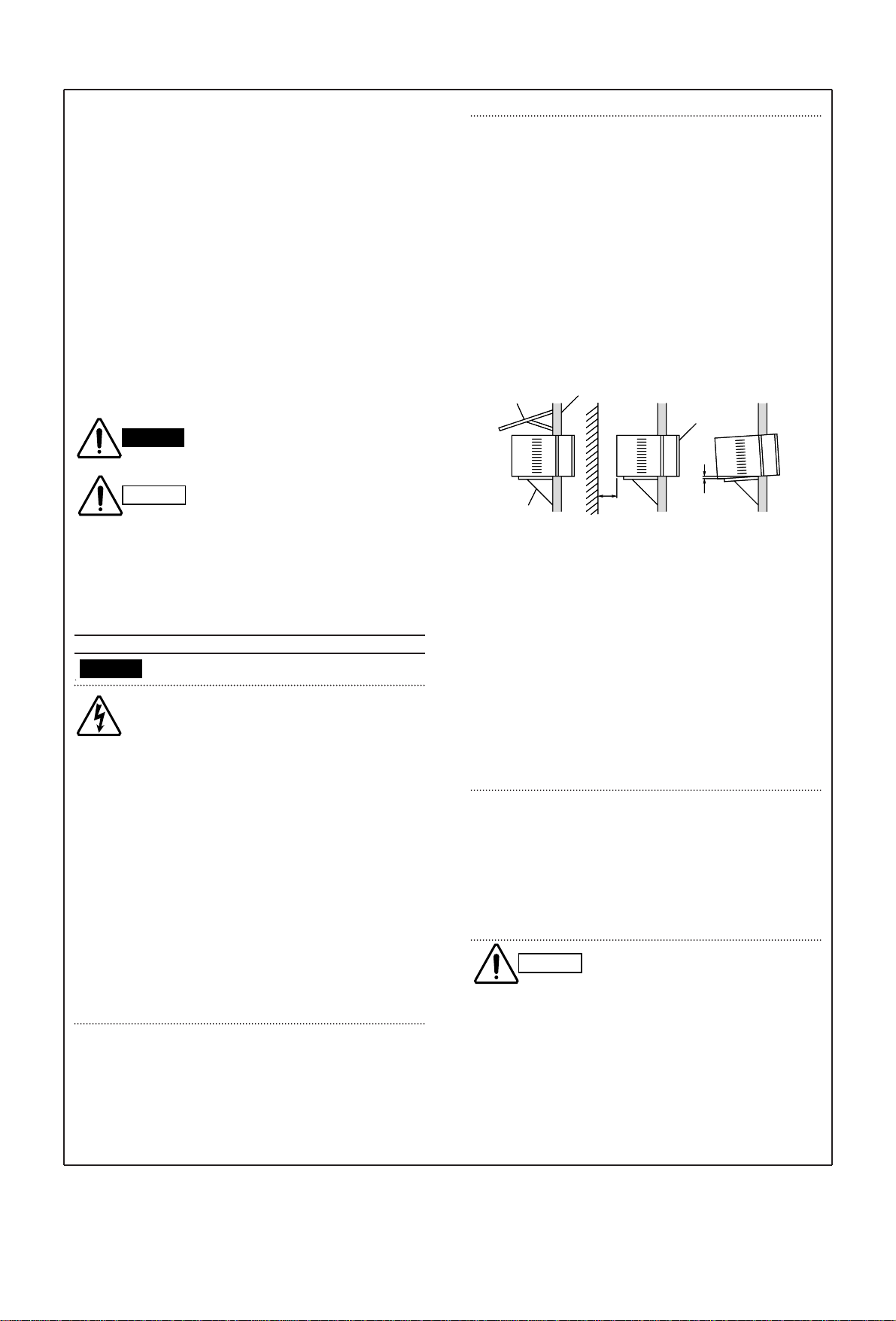
• If possible, install the unit in a shady location. If the site
is exposed to the sun, you should provide a sun screen
as shown in Fig. a.
• Install it at a spot where optimum cooling circulation can
be obtained. No chairs or other obstructions are allowed
in front of the air conditioner.
• The back of the air conditioner must extend outside.
(Be sure the right and left intake vents are not obstructed
by walls or windows.)
• Keep enough space from any outside obstruction (wall,
bush, etc.).
• To provide water drainage, the unit must be tilted at a
downward angle 0.5 to 1 cm to the outside.
• While installing the air conditioner, be sure to loosen the
compressor locking nuts to avoid abnormal noise and
vibration. (NOTE: Locking nuts are not provided on some
models.)
• As a safety measure, it is recommended that two people
install the unit: one to hold and balance the unit — the
other to lower the window frame to secure the unit.
• Hold the unit securely, and be careful to not drop the
cabinet or any parts if the air conditioner is being
installed on an upper floor of a multistory building.
When Servicing
• Turn the power OFF at the main power box (mains)
before opening the unit to check or repair electrical parts
and wiring.
• Keep fingers and clothing away from any moving parts.
• Clean up the site after you finish, remembering to check
that no metal scraps or bits of tools have been left inside
the unit being serviced.
Others
• Ventilate any enclosed areas when installing or testing
the refrigeration system. Escaped refrigerant gas, on
contact with fire or heat, can produce dangerously toxic
gas.
• Confirm upon completing installation that no refrigerant
gas is leaking. If escaped gas comes in contact with a
stove, gas water heater, electric room heater or other
heat source, it can produce dangerously toxic gas.
CAUTION
Outside
Wall
Enough space
from obstacle
or wall.
Tilt 0.5 to 1 cm
downward to outside.
Room
side Front
grille
Wall
Screen
Tilt 0.5 to 1 cm
downward to outside.
Support
i
WARNING
CAUTION
Fig. a

HOW TO USE THIS MANUAL
This manual is designed to help service personnel to understand basic functions, operation and possible troubles
and their remedies on SANYO window type air conditioners. You can use this manual both as a reference to find
specific information about the capacity, construction of the unit, and as a source of information to help you set up
and maintain the air conditioner. Please use this manual to make your work easier, keep the air conditioner
functioning well, and keep your customer satisfied.
Please read IMPORTANT ! precautional information on the previous page before you start actual work.
SANYO WINDOW TYPE A/C NOMENCLATURE
SANYO window type air conditioner is identified by a model number. Cooling or heating capacity, electrical
information and special features included on the air conditioner are indicated on the model number.
ii
Example
SA–93AH
Type
SA : SANYO window type A/C
Capacity
9 : 9,000 BTU/h class
Design Number
Special Features
AH : Mechanical Control,
Side Air Discharge
Heat Pump
NOTE
To identify the correct model number of your air conditioner, you must find the nameplate.

Table of Contents
Page
1. OPERATING RANGE ............................................................................................................................... 1
2. SPECIFICATIONS
2-1. Unit Specifications.......................................................................................................................... 2
2-2. Major Component Specifications.................................................................................................... 3
2-3. Other Component Specifications.................................................................................................... 4
3. DIMENSIONAL DATA............................................................................................................................... 5
4. REFRIGERANT FLOW DIAGRAM .......................................................................................................... 6
5. PERFORMANCE DATA
5-1. Cooling Capacity ........................................................................................................................... 7
5-2. Heating Capacity ........................................................................................................................... 8
6. ELECTRICAL DATA
6-1. Electric characteristics.................................................................................................................... 9
6-2. Electric Wiring Diagram.................................................................................................................. 10
7. TROUBLESHOOTING
7-1. Check before and after troubleshooting ........................................................................................ 11
7-2. Air conditioner does not operate .................................................................................................... 12
7-3. Some part of air conditioner does not operate ..............................................................................14
7-4. Air conditioner operates, but abnormalities are observed ............................................................. 16
8. CHECKING ELECTRICAL COMPONENTS
8-1. Measurement of Insulation Resistance .......................................................................................... 17
8-2. Checking Motor Capacitor.............................................................................................................. 18
8-3. Checking Fan Motor Winding......................................................................................................... 18
8-4. Checking Compressor Motor Winding............................................................................................ 18
9. DISASSEMBLY PROCEDURES
9-1. Removing Front Grille..................................................................................................................... 19
9-2. Removing Cabinet.......................................................................................................................... 20
9-3. Removing Electrical Component Box............................................................................................. 20
9-4. Removing Evaporator..................................................................................................................... 21
9-5. Removing Blower Wheel................................................................................................................ 21
9-6. Removing Condenser..................................................................................................................... 22
9-7. Removing Propeller Fan................................................................................................................. 22
9-8. Removing Fan Motor...................................................................................................................... 22
10. FUNCTION.............................................................................................................................................. 23
Unit Display and Control Panel ............................................................................................ 24
APPENDIX
iii

1
1. OPERATING RANGE
Temperature Indoor Air Intake Temp. Outdoor Air Intake Temp.
Cooling Maximum 32°C D.B. / 23°C W.B. 43°C D.B.
Minimum 19°C D.B. / 14°C W.B. 19°C D.B.
Heating Maximum 27°C D.B. 24°C D.B. / 18°C W.B.
Minimum 16°C D.B. – 8°C D.B. / – 9°C W.B.

2
2. SPECIFICATIONS
2-1. Unit Specifications
Model SA–93AH
Power Source 240V Single phase 50Hz
Voltage rating 240 V
Performance Cooling Heating
Capacity kW 2.40 2.50
BTU/h 8,200 8,500
Air circulation (High)
m3/h 410
Moisture removal (High) Liters/h 1.5 —
Electrical Rating Cooling Heating
Available voltage range V 216 ~ 264
Running amperes A 4.4 3.8
Power input W 1,050 900
Power factor % 99 99
C.O.P. W/W 2.29 2.78
Starting amperes A 18
Features
Controls / Temperature control Mechanical / Thermostat
Control unit —
Timer —
Fan speeds 2
Airflow direction (Indoor) Horizontal Auto
Vertical Manual
Air filter / Air exhaust Washable / Yes
Compressor Rotary (Hermetic)
Refrigerant / Amount charged at shipment g R22 / 760
Refrigerant control Capillary tube
Operation sound Indoor : Hi / Lo dB-A 46 / 44 46 / 44
Outdoor : Hi / Lo dB-A 50 / 48 50 / 48
Slide-out chassis Yes
Accessories —
Dimensions & Weight
Unit dimensions Height mm 345
Width mm 440
Depth mm 605
Package dimensions Height mm 416
Width mm 536
Depth mm 700
Weight Net kg 37.0
Shipping kg 39.0
Shipping volume
m30.16
DATA SUBJECT TO CHANGE WITHOUT NOTICE.
Remarks:
Rating conditions are:
Cooling : Indoor air temperature 27°C D.B. / 19°C W.B.
Outdoor air temperature 35°C D.B. / 24°C W.B.
Heating : Indoor air temperature 20°C D.B.
Outdoor air temperature 7°C D.B. / 6°C W.B.

3
2-2. Major Component Specifications
Model SA–93AH
Controller PCB
Part No. —
Controls —
Control circuit fuse —
Remote Control Unit —
Compressor
Type Rotary (Hermetic)
Compressor model 2P17C225AND
Source 240V Single phase 50Hz
Nominal output W 920
Compressor oil ... Amount cc ATMOS M60 or SUNISO 4GDID ... 350
Coil resistance (Ambient temp. 25°C) ΩC–R : 3.61
C–S : 4.97
Safety devices Type External protector
Overload relay MRA98776
Operating temp. Open °C Automatic opening
Close °C Automatic reclosing
Operating amp.(Ambient temp. 25°C) —
Run capacitor µF 25
VAC 400
Fan & Fan Motor Indoor Outdoor
Type Centrifugal Propeller
Dia. / Depth mm ø180 / D85 ø285 / D90.7
Fan motor model ... Q'ty YSK45-4A/K ... 1
Source 240V Single phase 50Hz
No. of poles ... rpm (240 V, High) 4 ... 1,100
Nominal output W 40
Coil resistance (Ambient temp. 20°C) ΩWHT-BRN : 212
WHT-VLT : 52
VLT-YEL : 13
YEL-RED(PNK) : 119
Safety devices Type Thermal protector
Operating temp. Open °C 135
Close °C Automatic reclosing
Run capacitor µF 3.5
VAC 440
Heat Exch. Coil
Coil Evaporator Condenser
Rows 3 3
Fin pitch mm 1.4 1.8
Face area
m20.070 0.115
External Finish Acrylic baked-on enamel finish
DATA SUBJECT TO CHANGE WITHOUT NOTICE.

4
Model SA–93AH
4way Valve (Solenoid coil) STF-01AJ (Coil),SFT-0101 (Valve)
Rating AC 220 V , 50 / 60 Hz, 6/5 W
Coil resistance Ω(at 20°C) -
Thermostat (Defrost thermo) CT-7
Rating AC 250V, 50 / 60 Hz
Operating temp. °C Start of defrosting –8.5 ± 3
Release of defrosting 5±4
Auto Deflector Motor MA062299
Rating AC 200/240V, 50/60Hz, 20mA, 4W, 5.0/6.0 rpm
Coil resistance kΩ(at 20°C) 9.92
2-3. Other Component Specification

5
3. DIMENSIONAL DATA
Model SA–93AH
241 440
345
46 ✽228 605
Slits for
ventilation
Side view (L) Front view Side view (R)
Power code
outlet Power code
outlet
Unit : mm
Dimension with "✻" mark indicates the maximum allowable wall thickness required for ventilating the unit.
NOTE

4. REFRIGERANT FLOW DIAGRAM
6
Model SA–93AH
Compressor
4-way
valve
Accumulator
Indoor heat
exchanger
Cooling cycle
Heating cycle
Capillary
tube
Outdoor heat
exchanger

7
5. PERFORMANCE DATA
Model SA–93AH
RATING CAPACITY 2.40 kW
AIR FLOW RATE 410
m3/h
EVAPORATOR CONDENSER
ENT. TEMP. °C OUTDOOR AMBIENT TEMP. °C
W.B. D.B. 20 25 30 35 40 43
TC 2.42 2.31 2.21 2.10 1.97 1.82
CM 0.71 0.77 0.83 0.89 1.02 1.16
21 SHC 1.77 1.72 1.67 1.62 1.56 1.50
15 23 SHC 2.04 1.99 1.95 1.90 1.84 1.77
25 SHC 2.32 2.27 2.21 2.10 1.97 1.82
27 SHC 2.42 2.31 2.21 2.10 1.97 1.82
29 SHC 2.42 2.31 2.21 2.10 1.97 1.82
31 SHC 2.42 2.31 2.21 2.10 1.97 1.82
TC 2.59 2.48 2.37 2.26 2.12 1.95
CM 0.73 0.79 0.85 0.91 1.05 1.19
21 SHC 1.48 1.43 1.39 1.34 1.28 1.21
17 23 SHC 1.76 1.71 1.66 1.61 1.56 1.48
25 SHC 2.03 1.98 1.94 1.89 1.83 1.76
27 SHC 2.31 2.26 2.21 2.16 2.10 1.95
29 SHC 2.58 2.48 2.37 2.26 2.12 1.95
31 SHC 2.59 2.48 2.37 2.26 2.12 1.95
TC 2.76 2.64 2.52 # 2.40 2.26 2.08
CM 0.76 0.82 0.88 0.94 1.08 1.22
21 SHC 1.19 1.14 1.09 1.04 0.99 0.92
19 23 SHC 1.46 1.42 1.37 1.32 1.26 1.19
25 SHC 1.74 1.69 1.64 1.59 1.54 1.47
27 SHC 2.01 1.96 1.92 1.87 1.81 1.74
29 SHC 2.29 2.24 2.19 2.14 2.09 2.02
31 SHC 2.56 2.51 2.47 2.40 2.26 2.08
TC 2.93 2.80 2.67 2.54 2.39 2.20
CM 0.78 0.84 0.90 0.97 1.11 1.25
23 SHC 1.17 1.12 1.07 1.03 0.97 0.90
21 25 SHC 1.44 1.40 1.35 1.30 1.25 1.18
27 SHC 1.72 1.67 1.62 1.58 1.52 1.45
29 SHC 1.99 1.94 1.90 1.85 1.80 1.73
31 SHC 2.27 2.22 2.17 2.13 2.07 2.00
TC 3.10 2.97 2.83 2.67 2.50 2.33
CM 0.79 0.86 0.92 0.99 1.14 1.28
23 25 SHC 1.13 1.09 1.04 0.98 0.93 0.87
27 SHC 1.41 1.36 1.31 1.26 1.20 1.15
29 SHC 1.68 1.64 1.59 1.53 1.48 1.42
31 SHC 1.96 1.91 1.86 1.81 1.75 1.70
TC : Total Cooling Capacity (kW)
SHC : Sensible Heat Capacity (kW)
CM : Compressor Input (kW)
Rating conditions (#Mark) are
Outdoor Ambient Temp. 35°C D.B.
Indoor Unit Entering Air Temp. 27°C D.B. / 19°C W.B.
240V Single Phase 50Hz
5 -1. Cooling Capacity

5-2. Heating Capacity
8
Model SA–93AH
–5 0 5 710 15
Outdoor temperature (°C D.B.)
0
10
20
30
40
50
60
70
80
90
100
110
120
Heating capacity ratio (%)
NOTE 1) … Point of Rating condition
Black dot in the chart indicate the following rating condition.
Indoor : 20°C D.B.
Outdoor : 7°C D.B. / 6°C W.B.
2) Above characteristics indicate instantaneous operation, which does not take into
account defrost operation.
3) When the outdoor temperature is below freezing, the following problems may
occur, depending on the temperature and humidity condditions:
• The heating capacity may be substantially lowered.
• Heating operation and defrosting may occur repeatdly in alternation.
• If operation continues under the above condition, the outdoor heat
exchanger may freeze
The above problem are not due to a malfunction. The air conditioner is simply
not capable of countinuous heating operation under such temperature and
humidty conditions. In such cases, turn off the air conditioner and use another
heating device.
–8
Fan speed : High

9
6. ELECTRICAL DATA
6-1 Electrical Characteristics
Model SA–93AH
COOLING Fan Motor Compressor Complete Unit
Performance at 240V Single phase 50Hz
Rating Conditions Running Amps. A 0.45 3.95 4.4
Power Input kW 0.110 0.940 1.05
Full Load Conditions Running Amps. A 0.45 5.45 5.9
Power Input kW 0.110 1.280 1.39
Rating Conditions : Indoor Air Temperature 27°C D.B. / 19°C W.B.
Outdoor Air Temperature 35°C D.B.
Full Load Conditions : Indoor Air Temperature 32°C D.B. / 23°C W.B.
Outdoor Air Temperature 43°C D.B.
HEATING Fan Motor Compressor Complete Unit
Performance at 240V Single phase 50Hz
Rating Conditions Running Amps. A 0.45 3.35 3.8
Power Input kW 0.110 0.790 0.90
Full Load Conditions Running Amps. A 0.45 5.25 5.7
Power Input kW 0.110 1.220 1.33
Rating Conditions : Indoor Air Temperature 20°C D.B.
Outdoor Air Temperature 7°C D.B. / 6°C W.B.
Full Load Conditions : Indoor Air Temperature 27°C D.B.
Outdoor Air Temperature 24°C D.B. / 18°C W.B.

10
6-2 Electrical Wiring Diagrams
Model SA–93AH
To avoid electrical shock hazard, be sure to
disconnect power before checking, servicing
and/or cleaning any electrical parts.
WARNING
DATA SUBJECT TO CHANGE WITHOUT NOTICE.

7. TROUBLESHOOTING
7-1. Check before and after troubleshooting
7-1-1. Check power supply.
●Check that voltage is in specified range (±10% of the rating).
●Check that power is being supplied.
7-1-2. Check lead wires and connectors.
●Check that coating of lead wires is not damaged.
●Check that lead wires and connectors are firmly connected.
●Check that wiring is correct.
11
Hazardous voltage can cause ELECTRIC SHOCK or
DEATH. Disconnect power or turn off circuit breaker
before you start checking or servicing.
WARNING

7-2. Air conditioner does not operate.
7-2-1. Circuit breaker trips (or fuse blows).
A. When the circuit breaker is set to ON, it is tripped soon. (Resetting is not possible.)
●There is a possibility of ground fault.
●Check insulation resistance.
If resistance value is 2MΩor less, insulation is defective (“NO”).
1. If any poorly insulated part is found, exclude that part from circuit with other parts properly connected, and then
measure insulation resistance of entire air conditioner again to locate defective part.
2. Replace defective part with new one.
NOTE
Measure insulation
resistance of electrical
parts.
(Example)
Compressor, Fan motor,
Capacitor, Relay etc.
NO
Set circuit breaker to OFF.
*
1Pull the power plug out of the
wall outlet.
Measure insulation resistance
of unit.
•
•
Insulation of
unit is
defective.
WARNING
Window type air conditioner
Wall outlet
(Receptacle)
Power
supply
Circuit
breaker
Ground
1
Power plug
12

B. Circuit breaker trips in several minutes after turning the air conditioner on.
●There is a possibility of short circuit.
7-2-2. Neither fan motor nor compressor motor runs.
A. Power is not supplied.
B. Check OPERATION SELECTOR switch on the control panel.
If it is set at OFF.
•Check that OPERATION SELECTOR
switch is not set at " "(OFF). Set to "COOL "
or "HEAT ".
NO
•Check power supply.
Power is being supplied to the unit.
Circuit breaker
is tripped.
Power failure.
Reset breaker.
Wait for recovery
or contact power
company.
Replace with suitable
one (larger capacity).
•
•
•
NO
Check capacity of circuit breaker.
Capacity of circuit breaker is
suitable.
Measure resistance of fan motor
winding.
Measure resistance of compressor
motor winding.
•Measure resistance of 4-way valve's
winding.
In case of Heating operation :
13

7-3. Some part of air conditioner does not operate.
7-3-1. Only fan does not run.
7-3-2. Auto deflector switch does not work.
Auto deflector does not work with the operation selector switch in FAN or OFF position.
NOTE
•OK •Measure resistance of auto deflector
motor winding.
Check that OPERATION SELECTOR
switch is set at either "COOL "
or "HEAT ".
Fan cannot
be turned.
OK
•Check fan rotation.
Turn fan gently once or twice by
hand.
•Check fan casing
foreign matter on
inside.
Fan motor burnout
or foreign matter in
bearings.
Remove foreign
matter or repair.
Repair or replace.
•Measure resistance of fan motor
winding.
•Check fan motor capacitor.
14

7-3-3. Only compressor does not run.
A. Check setting temperature.
B. Check compressor and electrical parts.
●If the unit is turned off during cooling (or heating), DO NOT restart it immediately, as this can damage it. Wait at
least three minutes before starting it again.
CAUTION
•Check compressor motor
capacitor.
•Measure resistance of
compressor motor winding.
NO
YES
YES
Overload relay is working.
YES
Temperature of compressor
is abnormally high.
Refrigerant gas shortage. Charge refrigerant gas (R22).
Rotor may be locked up.
•Measure power supply
voltage.
The voltage is too low.
No
NO
Is room temperature too low ?
Try to lower setting temperature by
thermostat knob COOLER.
COOL
NO
Is room temperature too high ?
Try to raise setting temperature by
thermostat knob WARMER.
HEAT
15

7-4. Air conditioner operates, but abnormalities are observed.
7-4-1. Operation does not switch from HEAT to COOL (or COOL to HEAT)
7-4-2. Poor cooling or heating
7-4-3. Excessive cooling or heating
NO
•Set temperature is suitable. Set temperature to higher or
lower value using thermostat
on the control panel.
Air filter is clogged.
Temperature
difference
is small.
YES
Temperature difference between
suction and discharge air is
large enough (approx. 10 deg. or more).
Possibility of
gas shortage.
•Measure temperature of suction and
discharge air of air conditioner. Charge refrigerant
gas (R22).
Check for clogging of air filter.
•Fan speed is set to LOW.
Clean filter.
Set fan speed to
HIGH.
•Review cooling load estimate,
if performance of air conditioner is
normal.
Reduce cooling or heating
load or replace the air
conditioner with larger
capacity.
•Measure resistance of 4–way valve's
winding.
16
Table of contents
Other Sanyo Air Conditioner manuals

Sanyo
Sanyo SAP-CMRV3656EH Operating manual

Sanyo
Sanyo SAP-K77RAX Operating manual

Sanyo
Sanyo KS0971 Installation and user guide

Sanyo
Sanyo SAP-KRV96EHDS Operating manual

Sanyo
Sanyo CH3082 Operating manual

Sanyo
Sanyo V3622 User manual

Sanyo
Sanyo SA-128S5-A Operating manual

Sanyo
Sanyo 30K12W User manual

Sanyo
Sanyo CHDXR09663* User manual

Sanyo
Sanyo SAP-KM97AHA Operating manual

Sanyo
Sanyo C1211 Owner's manual

Sanyo
Sanyo 09KLS71 User manual

Sanyo
Sanyo C4272R User manual

Sanyo
Sanyo KS2462R User manual

Sanyo
Sanyo SAP241TC User manual

Sanyo
Sanyo ECO-i SPW-UMR74EXH56 Manual

Sanyo
Sanyo KH2442 User manual

Sanyo
Sanyo FH1232 User manual

Sanyo
Sanyo SAP361TC User manual

Sanyo
Sanyo CR1154GDZH8 User manual