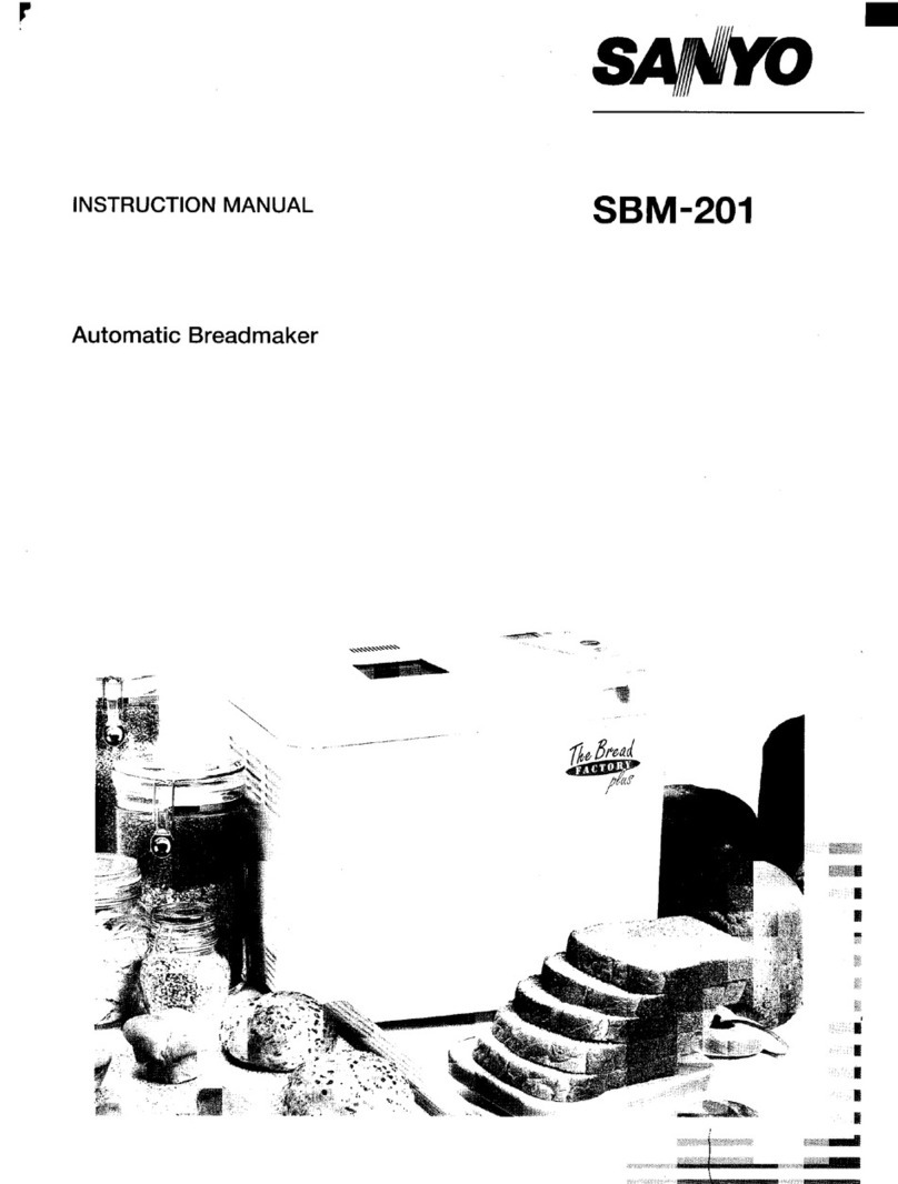
Sanyo SBM-201 User manual

SERVICE MANUAL Automatic Bread Maker
FILE NO.
SBM-201
PRODUCTIONCODENO.
343631822 (New Zealand)
343631829 (Malaysia)
REFERENCE NO. SM-680078

i. Specifications b
New Zealand 230V(50HZ)
Power Source Malaysia 240V(50HZ)
New Zealand 430W
Heater
Power Consumption Malaysia 470W
Main Motor 50Hz 1Oow
Outer Dimensions 399(W)X246( D)X324(H) mm
Weight IApprox. 7.Okg
Timer I1hr. up to 13hrs. (Digital)
Cord Approx. 1.4m length
Thermial Fuse Baking temp. 157°C
New Zealand Instruction manual, Cook book
Accessories Malaysia Insutuction manual, measuring cup
2. Constructions and Operation
1.ConstructIons
The kneader blade attached to the inner pot ass’y is rotated by the main motor by way of the pulley and
the belt. The ingredients inside of the inner pot are kneaded by the kneader blade. The inside of the
temperature is controlled by the thermal sensor and the heater between the processes of “kneading”
and “baking” .—
1

i
IOutline of Constructions
II
I
[1 I
Lk.. uw
Hopperass’y \
Blade
d
,, ,,
—\ \ lr
\r
11II1.
rf
IIf
/
—
/ /
/
d“d
Sensor ass’y
/
Fuse ass’y
,Motor
I
2

i
3. Circuit Diagram
The sign A:
The parts marked with ~have special characteristics important for safety.
When replacing any of these parts, use only manufacturer’s specified parts.
-,
=1I
CJ $L-.-J tAITI–r
m.HAC102
J1
.
L-.:–
!! . .
l.At!- 11
Q-4’!kdir--------------T=-Ti-’
a’
0(
s.,
z,1
,1
q,1
,1
C)s ,1
,1
50,1
C108 ,1
,1
+,!
.---- ----.---- ii
B
11L&’F
-!, . .
------
ng1,- -0
.+a ,= ---------
sZol L-,N
D
03 .g
@
------------------ ----- -------. ,C9
I-YL_.l
Il.-e+ :D2 III
I
,m
WC)
!-----------------------------------------------------------------------------------------------------
,
,
1
,
,
,
,
,
0
,
,
.-
3

ii
(ELECTRICAL PARTS LIST)
-POWER SUPPLY UNIT
L
SYMBOL SPECIFICATION
Iclol IC AN78N05
PH101, PH102 Photo Couple MOC3021
Q101, Q102, Q103 Digi. Tra. DTC114ES
Q104,Q105 Diai. Tra. DTA143ZS
D101,D102, D103 Diode DSK-1OEor 1N4004
D104
TAC101 ,TAC102 Triac Q6004L3 or TM561S-L
VAR101 Varistor TNR7G431 Kor VE09M02750K
VAR102 Varistor MFCN08D431 K
LI 01 Coil SL02B121 orTC50-1250K-06
C103, C109 ]Metallized Film Ca~. 0.1UF250V
C104, C105 Metallized Film Cap. 0.1pF 50V
Cl 06 Ceramic Cap. 0.1uF 50V
C107 IElectrolytic Cam 10OOUF25V
.,---r ——
C108 Electrolytic Cap. 470pF 6.3V
R101 Carbon Resistor 2.7Mfl l/2W
R109 ICarbonResistor 10Kf2 l/4W
R106, R107 Carbon Resistor 560fl l/2W
R104, R105 Metal Oxide Resistor 220t2 1W
R102, RI 03, R108 IMetal Oxide Resistor 100(1 l/2W
BZ101 Piezo BuzzerPKM17EPP-4001
PT101 Power TransformerT35-0240
CONTROL UNIT
SYMBOL SPECIFICATION
icl IC pPD75064CU-028
Q1 Transistor 2SC1740S or 2SC1570
Q2 Digi.Tra. DTC114ES
Q3,Q4,Q5,Q6 Digi. Tra. DTA143ZS
LD1 LEDA-3335H
LD2 LED5133D
D1,D2,D3,D4,D5 Diode 1SS131
ZD1,ZD2 Zener Diode RD12ESB2 or RD12ESB3
cl, C3 Ceramic Cap. 0.1pF 50V
C5, C6 Ceramic Cap. 10OOPF50V
C7, C8, C9 Ceramic Cap. O.OlpF 50V
C2 Electrolytic Cap. 10OpF6.3V
C4 Electrolytic Cap. 4.7pF 50V
R2 Carbon Resistor 10KL2 l/4W
R4, R5, R9, R1O Carbon Resistor 2.2Kt3 l/4W
Rll, R12, R13 Carbon Resistor 300C4 l/4W
R14, R15, R16
R17, R18
R1,R8 Carbon Resistor 4.7KCI l/4W
R3 Carbon Resistor 560S2 l/4W -
R7 Metal Film Resistor 1.8K(I l/4W
R8 Metal Film Resistor 30KLI l/4W
xl Ceramic Osc.CST4.19MGW-TFO1
Swl ,SW2, SW3, Key Switch KPT-1115A
SW4, SW5, SW6,
4

4. Operational Principles
1) Operation procedures
Refer to the separate instruction manual.
2) Block diagram
Power
transformer Power circuit
m------
I I 7
+Heater control k!------] ::::i~’m’ I___
IIII
3) Power circuit
=ircuit diagram
----J
Icl
Indicator circuit
=
-
---EEcl
1
POWERSUPPLYUNIT ()CONTROLUNIT
1
I
Iclol
IN OUT
I121 VDD
IT T T IT
l-piG
+ +
TC106 Clul Ibl
I
II
Vllul 1]D101-D1o4, L1I1t1
f“q Vss
II
+oltage at each point (Ground is shown as Vss) I
I
@13V @5V
●Description of operation
(1) VDD-VSS Power supply (5V)
The secondary output of power transformer(PT101 )is given bridge-rectification by the diode
(D101 -D104) and the condenser (C107) to produce 13V voltage at@. The voltage at@is used to
compose@ 5V power supply by the operation of constant voltage circuit consisting of 3-terminal
output voltage regulator (ICI 01).
5

ii
w
4) Heater and motor control circuits
●
Circuit diagram
m‘F
(N04
010!
~+13 21
.
IAI
(%
Q102
M
Rl(
Ca -t---
1
C9
1-
VDD
P60
P61
Ic 1
Wss
●Description of operation
(1) Heater control circuit
When the voltage at pin 13 of the micro computer (ICI) becomes Low (OV), the signal will drive
transistor (QI 05), transistor (Ql 03), Photo triac (PH101 ), and thentriac(TAC101 )to operate the
heater,
(2) Motor control circuit
When the voltage at pin 14 of the micro computer (IC1)becomes Low (OV), the signal will drive
transistor (Q104), transistor (Ql 02), Photo traiac (PH102), and thentriac(TAC102) to operate the
motor.
5) Control circuit for inner temperature
●Circuit diagram
2’~VDD
z
1- 17
)AN1
i?”“--G Ii i?: ~
25 P20 Icl
42 Vss
.Description of operation
(1) The circuit controls the inner temperature during the timer setting and starl of operation.
w
6

5. Characteristics of Baking (Operation Processes)
l-Basic (Normal)
KEEP
SettingKNEADKNEADFIRST PUNCHREST SHAPEFINAL BAKE WARM
10min. @@RISE DOWN RISE *2
-9 hre. 39min. 49rein, Mex.
50min. 5min. 20min. 50sec. 10sec. 25min. 15sec. 45 sec. 50 min. 60 min.
<>
120”C
30°c
14°C
rHeater ON/OFFOFF OFF ON/OFFOFF ON/OFFOFF ON/OFF
OwOFFONK)FF
Mainmotor OFF *’ON ON OFF ON OFF ON OFF OFF OFF
LED(Cpsrstbn)ON ON ON ON ON ON ON ON ON OIWOFF
2-Basic (Dark) L
Setting
10rein,
-9 hrs
40min
1-
14°C
II
3-Basic (Rapid)
Ml14_
KNEADKNEADFIRST PUNCHREST SHAPEFINAL BAKE
5min. 20min. 50sec. 10sec. 25min. 16W. 45sec. 60min
J4-u4-T
——. —.
OFF OFF ON/OFFOFF OfVOFFOFF OFJOFF
‘ON/OFF
*‘ON ION OFF ON OFF ON 10 FF OFF
II{I1 1 1
ON ION] ON\ ON ION ION\ ONION
i
KEEP
WARM
*2
Max.
60 min.
ON/DFF
FF
!2K?.E.
KEEP
SettingKNEADKNEADFIRST PUNCHREST SHAPEFINAL BAKE WARM
@@RISE DOWN RISE *2
10min. 16min. 29min. Msx.
-11hre. 5min. 20min. 50sec. loeec. 8min. 10sec. 50sec. 40min. 60min.
(>
120”C
30”C
14°C
LHeater ONIOFFOFF OFF ON/OFFOFF ON/OFFOFF ON/OFF
‘ON/OFFOWOFF
Mainmotor OFF *’ ON ON OFF ON OFF ON OFF OFF OFF
LED(Opsrstii) ON ON ON ON ON ON ON ON ON OfVOFF
7
Time until finish
of BAKE
3hrs.10min.
Time until finish
of BAKE
3hrs. 20 min.
Time until finish
of BAKE
2hrs.

4-Whole Wheat
KEEP
Setting REST KNEADKNEAD FIRST PUNCHREST SHAPE FINAL BAKE WARM
10min. @@RISE DOWN RISE *2 Time until finish
-9 hrs. 49min. 44 min. Max. of BAKE
30min. 30min. 5min. 15min. 50sec. 10sec. 25 min. 10sec. 50Sec. 40 min. wmin. 3hrs, 30 min.
<>
120”C
30°c
Heater OWOFFON/OFF OFF OFF ON/OFF OFF ON/OFF OFF “OtVOFFOwOFFON/OFF
Mainmotor OFF OFF *’ ON ON OFF ON OFF ON OFF OFF OFF
LED(Operation)ON ON ON ON ON ON ON ON ON ON ON/OFF
w
5-Rye
KEEP
Setting KNEADKNEAD FIRST PUNCHREST SHAPE FINAL BAKE WARM
10min. @@RISE DOWN RISE *2 Time until finish
-lOhrs. 39min. 49min. Max. of BAKE
7min. 5min. 13min. 45 sec. 15sec. 15min. 10sac. 50sec. 50min. Ml min. 2hrs. 53 min.
6>
125°C
30”C
14°C
LHeater ON/OFF OFF OFF ON/OFF OFF ONIOFF OFF ON/OFFON/OFFON/OFF
Main motor OFF ●’ON ON OFF ON OFF ON OFF OFF OFF
LED(Operation)ON ON ON ON ON ON ON ON ON ON/OFF
L
6-Quick
KNEADKNEADKNEADREST KNEADKNEADBAKE
@ @ @ @ @ Timeuntilfinish
2min. 1min. 1min. 91 min. of BAKE
30sac. 30sac. 2min. 30sac. 30sec. 30sac. 30sec. lhrs. 40 min.
<—*>
105°C
Heater OFF OFF OFF OFF OFF OFF ON/OFF
Main motor *’ ON *’ON ON OFF *’ON ON OFF
LED(operation) ON ON ON ON ON ON ON ‘
8

7-French
Setiing KNEADKNEAD FIRST
10min. @@RISE
-9 hre. 39 min.
30 min. 5min. 20 min. 50 sec.
PUNCH
DOWN
10sec.
<
30”C
14°C
REST
30min.
-uKEEP
SHAPE FINAL BAKE WARM
RISE *2
59 min. Max.
10sec. 50sec. 55min. 60min.
125°C
OFF ON OFF OFF OFF
ON] ON\ON ON 10twOFF
Time untii finish
of BAKE
3hrs. 30 min.
Heater ON/OFFOFF OFF ON/OFFOFF
Mainmotor OFF *’ON ON OFF ON
LED(Opsrsliin) ON ‘ON ‘ON ‘ON ‘ON
8-Sweet
KEEP
Setting KNEADKNEAD FIRST PUNCHREST SHAPE FINAL BAKE WARM
10min. @@RISE DOWN RiSE *2 Time untiifinish
-9 hrs. 39min. 49 min. Ms)(. of BAKE
35min. 5min. 20 min. 50sac. 10See. 25 min. 5sec. 55 sec. 65min. 60min. 3hrs. 25 min.
<>
105°C
30”C
14°C
Heater ON/OFFOFF OFF ON/OFFOFF ON/OFFOFF ON/OFF
AON/OFFON/OFF
Mainmotor OFF *=N ON OFF ON OFF ON OFF OFF OFF
LED(OperstiGII)ON ON ON ON ON ON ON ON ON ON/OFF
9-Pizza Dough
Heater
Mainmotor
LED(Opersthn]
---1-
Setting KNEAD
10 min. @
-12 hrs.
10 min. 5min.
-=-L
I
ONIOFF ~OFF
OFF t“’ ON
ON ON
KNEAD
@
15 min.
OFF
ON
ON
9
RISE
30min. 3
30”C
ON/OFF
OFF
50 min.
--m--J

i
10-Dough
Heater
Main motor
LED(Oparatiin:
30”C
14°C /
!I
I I
@OFF IOFF OFF tONIOFF
I
I
OFF I●’ON ON IOFF
I
III
ON ON ON ON i
PASTA
KNEAD KNEAD KNEAD
@ @ @
1min. 2min. 5min.
.=
Heater
Mainmotor
LEO(Operation
OFF OFF OFF
I
I
*’ON *’ ON ON
I I
ON ON ON
REST KNEAD
@
1min. 5min. 14 min.
>
OFF OFF
OFF ON
ON ON I
*1During of the KNEAD process, the main motor is operated intermittently.
*2The KEEP WARM process is maximum 60 minutes. Even if within 60 minutes, when temperature
of sensor is under 80 temperature impressed, the keep warm is completed.
10

Key
Indication OPEf!AING
LED Operation Remarks
START STOP SELECTA(uP) W(down)PASTA
(1) POWER Basic \\llllll, OFF 0:00only flashes at 1.66Hz. When power
ON Operation C,C 00$ supply cord is
turned on.
/111111’
Operation xKeyinputis neglected.
against (Whileerrorissounding)
input oTo STOP(2)
o‘To SELECT(3)
xKeyinputisneglected.
(Whileerrorissounding)
xKey input is neglected.
(While error is sounding)
oTo PASTA(9)
(2) STOP Basic OFF Noindication WhenSTOP
Operation switchis
depressedin the
condition (1).
Operation xKey input is neglected.
against ,(While error is sounding)
input oTo STOP (2)
oTo SELECT (3)
xKey input is neglected.
(While error is sounding)
xKey input is neglected.
(While error is sounding)
oTo PASTA(9)
(i
ml

(((!
Key
Indication OPERATING
LED Operation Remarks
START STOP SEI.ECTA(uP) V(down) PASTA
(3) SELECT Basic OFF “1”is Indicated. WhenSELECT
Operation switchis
;depressedin the
condition (1) or
(2)
Operation 01 Menu selected with the Formenudisplay
against SELECT key is statted. seetheinstruction
\input oTo STOP (2) manual.
oThe display changes with each
oSELECT switch input.
To TIMER SEITING (4)
oTo TIMER SEITING (4)
oTo PASTA(9)
[4) TIMER Basic A(UP) 3: ;/-jOFF “310” isdisplayed.
SETTING Operation WhenA(up) or
(Incase of Basic (Normal) w(down) switch
is depressed in
the condition
A(down)3: ;~ (3).
Operation oStartsaccordingto timer setting.
against To START (6)
input oTo STOP (2)
oMovesonto menu select (5)of
timer setting.
o●When pressed,
TIMER SET time increases in time is added
10 minute increments. at high speed.
oTIMER SET time increases in ●When pressed,
10 minute increments. time is
oTo PASTA(9) subtractedat
highspeed.

STAR1
o
x
Key
Indication Operation Remarks
STOP
o
A(up]
o
V(dowf
o
PASTA
LED
OFF
SELEC1
o
When SELECT
switch is
depressed in the
condition (4)
[5) Menuselec
intimer
settings.
Basic
Operation ●
✎
✚
Operation
against
input
The time preset by the timer
setting key are starts counting.
To START (6)
To STOP (2)
Returns to display in timer
setting.
Returns to timer setting time
display.
To TIMER SET (5)
Returns to timer setting time
display.
To TIMER SET (5)
To PASTA (9)
Course change is
notcarried out.
Display time is
counted up 10
minutes.
Displaytime is
counteddown 10
minutes.
o
ON
:6) START Basic
Operation Displaybakingtime.
Operationstartsfor baking
timeselectedbythe SELECT
keyor thePASTAkey.
Thecolon (:) changesfrom
beingsteadilylitto flashing,
andthedisplayis counted
down1minuteat atime.
Whenthe START
keyispressed
afterselectionor
whenthetimer
hasbeenset.
x
Operation
against
input
Key input is neglected.
Movesonto STOP (2) with
input of 1second or more.
o
xKey inputisneglected.
Key input is neglected.
xKey input is neglected.
(
-,

(((
7) Keep
warm
mode
8) Keep
warm
complete
Basic
Operation
Operation
against
input
Basic
Operation
Operation
against
input
)PERATIN
LED
Flash
OFF
?TART
x
x
STOP
o
0
Key
T
SELECT
A(up)
T
x
x
1
x
x,
T(dowm
x
x
PASTA
x
x
Operation
The colon (:) in the “0:00”
display flashes.
Key input is neglected.
To STOP (2)
Key input is neglected.
Key input is neglected,
Key input is neglected.
Thecolon(:)changesfrom
flashingto beingsteadilylit.
Key input is neglected.
(No error warning)
To STOP (2)
Key input is neglected.
(No error warning)
Key input is neglected,
(No error warning)
Key input is neglected.
(No error warning)
Key input is neglected.
(No error warning)
Remarks
Changesto
“Keepwarm”
modeafter
bakingis
complete.
Warmingends1
hourafterstartof
keepwarmmods,
orwhenoven
temperatureis
80”Cor more.
ml

.-L
u-l
Key
Indication OPERATING
LED Operation Remarks
START STOP SELECTA(uP) V(down) PASTA
(7) PASTA Basic OFF
P
“0:14”isdisplayed. WhenPASTA
Operation ,: ~~: switchisdepressed
inthecondition(1)
or(2).
Operation IoMenu of PASTA is started.
against
input oTo STOP (2)
oTo SELECT (3)
oIndication is not changed.
oTo PASTA(9)
Demonstration (forinspection)
Inspection demonstration mode is set when power plug is connected to the power outlet while depressing all of SELECT, DOWN and START switches.
Operation is the same as ordina~ one. Only exception is that depressing of UP key at the time of starting makes the process move to the following one.

i
7. Disassembly Procedures
1. Disassembly of lid
(1) The lid ass’y can be dismounted while the lid open and pulling upward.
(2) The window, holder (window) and air window can be dismounted by removing tab of lid fixing frame.
(Fig. 1)
2. Disassembly of main unit
/(1) The bottom lid can be dismounted by removing 4fitting screws and 4 stands on the bottom lid.
(2) Removing the fitting screw on the rear and left side of control panel. The control panel can be
removed from the main unit by removing tab of control panel out of cabinet, through pressing
rightward on the rear surface of control panel. The control panel can be dismounted by removing
detached 2sockets from the control PCB ass’y.
(3) The control PCB ass’y can be removed from control panel by removing the 3fitting screws and tab
of control panel.
(4) Removing the 3fitting screws of the terminal. And removing the power cord ass’y can be
dismounted from the main unit by loosen the fasten screw of the cord bushing.
(5) The main unit can be pulled up after removing 6fitting screws of inner cabinet (U), and the main unit
and hinge can be separated out of cabinet. (Fig. 2) The cord bushing can be dismounted by
removing the net of the cord bushing from the cabinet.
(6) Cut the 3fixers that hold the lead wire. Then, remove the following sockets: socket from the motor,
socket from the heater, socket from the fuse ass’y, connector from the motor and connector from the
two lead wires.
(7) The power PCB ass’y can be dismounted by removing the fitting screw of power PCB ass’y and
fitting screw of support. (Fig. 3)
(8) The capacitor can be dismounted by removing the fitting screw. (Fig. 3)
(9) By removing the 3motor fitting screws,
Self-tap ing screw,
J’ Tappin screw
truss h.4x 8mm itrussh .4x Ilmm
v‘Figo2)
the motor ass’y and belt can be removed from frame, (Fig. 3)
bScrew,panspring
washer4x6mm (Fig. 3)
,16

ii
I
(10) The pulley (big) and holder can be dismounted by removing the pulley (big) fitting ring. (Fig. 4)
(11)Removing the fitting screw on the eafih read wire 65L of the chassis side. Removing the two lead
wires 155L, the earth lead wire 65L and two Ceramic Capacitor, fixed on the terminal. By removing
the terminal fitting screw, the terminal and the sheet can be dismounted.
(12) The power cord can be taked off by removing the cord bushing from chassis.
(13) The inner cabinet ass’y can be removed by removing the 3fitting screws of the holder (base) ass’y,
and setting tab of the shield to its horizontal position. (Fig. 3)
4)
(14) The shield can be removed by removing the 2fitting screws of the shield.
(15) Pull out the 2sockets of the lead wire from the heater. By removing the heater supporting insulator
(16)
(17)
(18)
fitting nut and the insulator Afitting hook@ of inner cabinet (M), the heater ass’y and insulator A
can be dismounted from the inner cabinet. (Fig. 5)
By removing the fitting screw of the holder (heater), the holder (heater) and the insulator can be
dismounted from heater ass’y. (Fig. 5)
The fuse unit can be dismounted by removing the screw inside of the inner cabinet which is fixing
the fuse unit. The fuse ass’y can be removed by straightening the fixing tab of the holder (fuse).
(Fig. 5)
The sensor ass’y and the holder (sensor) can be dismounted by removing the screw inside of the -
inner cabinet which is fixing the sensor ass’y. (Fig. 5)
Insluator A\
(Fig. 5)
17

i
)
(19) The spring plate can be taken out by removing its fitting screw.
(20) The joint ass’y, the holder (base) and tube can be dismounted by removing the holder (base) fitting
ring,
Precautions for Reassembly
(1)When mounting the power cord, the cord bushing should be attached to the cord holder so that the
dimensions between the bushing and the top of the terminal is approx. 25 mm. (Fig. 6)
(2) Wiring should be made as shown in the specified wiring diagram. (Fig. 6)
Power PCB zControl PCB
Black with socket
qL
Power PCB \ \
Motor’= Power PCB
Blue and Yellow with socket ,~flfl
~~ ]yea~h~;~B ‘r
5==’UI White with socket
.@.!.wL
--
(Fig. 6)
w
18

(3) When mounting
motor when the
pulley S.
the belt, the motor fitting screws are temporary to fit in the first place. Install
tension of the belt become 13kg, after the belt hangs on the pulley(big)
Belt
Ring C
Holder
Chassis
and
IIllustration of Wiring
the
the
1
Power PCB
r“
Power cord ‘LJ
Capacitor
Other manuals for SBM-201
1
Table of contents
Other Sanyo Bread Maker manuals

Sanyo
Sanyo SBM-15 User manual

Sanyo
Sanyo SBM-20 User manual

Sanyo
Sanyo SBM-20 User manual

Sanyo
Sanyo SBM-150 Quick guide

Sanyo
Sanyo SBM-20 User manual

Sanyo
Sanyo SBM-10 User manual

Sanyo
Sanyo SBM-10 User manual

Sanyo
Sanyo Bread Factory Plus SBM20 Quick guide

Sanyo
Sanyo SBM-20 User manual

Sanyo
Sanyo SBM-150 Technical specifications