manuals.online logo
Brands
  1. Home
  2. •
  3. Brands
  4. •
  5. Sanyo
  6. •
  7. Camcorder
  8. •
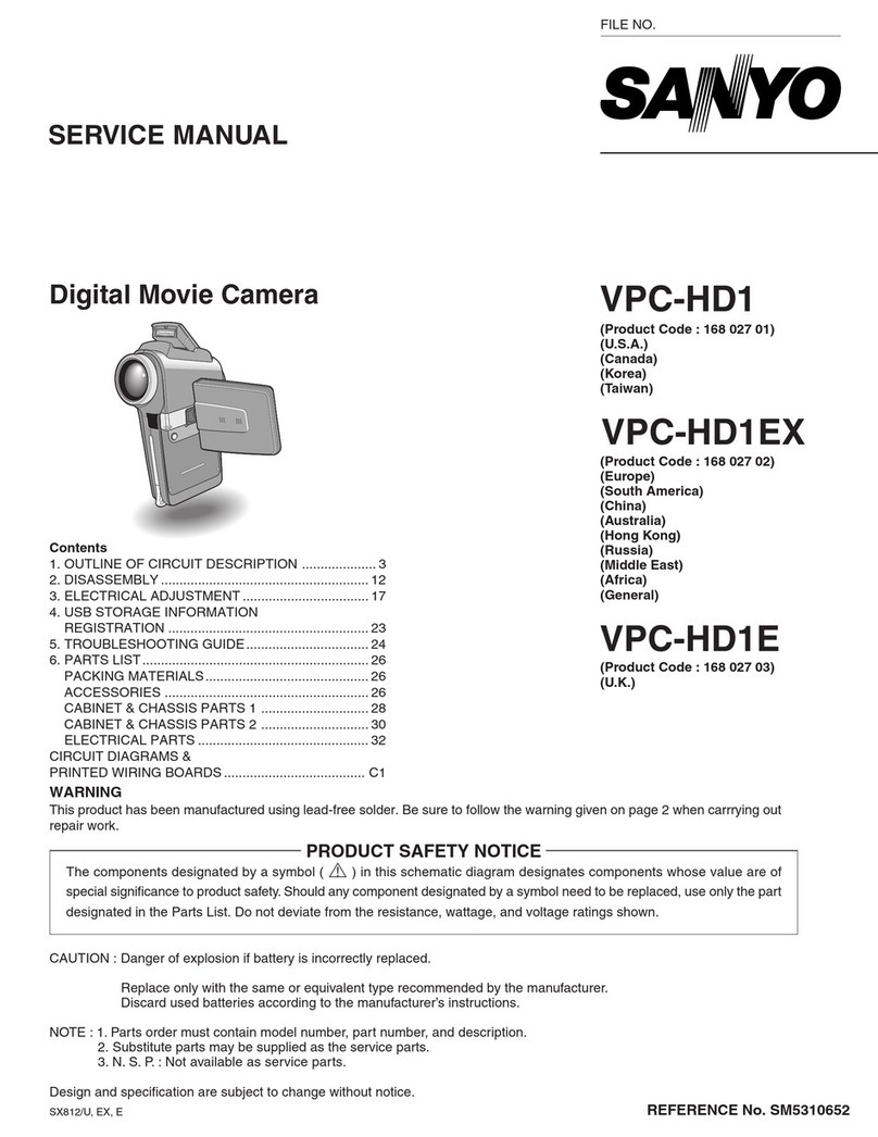
  9. Sanyo VM-EX400P User manual

Sanyo VM-EX400P User manual

This manual suits for next models

4

Other Sanyo Camcorder manuals

Sanyo DSR-C100 User manual

Sanyo

Sanyo DSR-C100 User manual

Sanyo VM-D90R User manual

Sanyo

Sanyo VM-D90R User manual

Sanyo Xacti VPC-C1 User manual

Sanyo

Sanyo Xacti VPC-C1 User manual

Sanyo VPC-SH1 - Full HD 1080 Video Assembly instructions

Sanyo

Sanyo VPC-SH1 - Full HD 1080 Video Assembly instructions

Sanyo VPC-CG20BK User manual

Sanyo

Sanyo VPC-CG20BK User manual

Sanyo VPC-HD1A User manual

Sanyo

Sanyo VPC-HD1A User manual

Sanyo Xacti VPC-WH1 User manual

Sanyo

Sanyo Xacti VPC-WH1 User manual

Sanyo Xacti VPC-GH3GX User manual

Sanyo

Sanyo Xacti VPC-GH3GX User manual

Sanyo Xacti VPC-CG6GX User manual

Sanyo

Sanyo Xacti VPC-CG6GX User manual

Sanyo VPC-CG21EX Assembly instructions

Sanyo

Sanyo VPC-CG21EX Assembly instructions

Sanyo Xacti VPC-FH1 Series User manual

Sanyo

Sanyo Xacti VPC-FH1 Series User manual

Sanyo Xacti VPC-HD2000 Series User manual

Sanyo

Sanyo Xacti VPC-HD2000 Series User manual

Sanyo Xacti VPC-WH1YL User manual

Sanyo

Sanyo Xacti VPC-WH1YL User manual

Sanyo Xacti VPC-HD1010GX User manual

Sanyo

Sanyo Xacti VPC-HD1010GX User manual

Sanyo VPC-CG20 - Full HD 1080 Video User manual

Sanyo

Sanyo VPC-CG20 - Full HD 1080 Video User manual

Sanyo VPC-CS1 - Full HD 1080 Video User manual

Sanyo

Sanyo VPC-CS1 - Full HD 1080 Video User manual

Sanyo XACTI VPC-GH3EX User manual

Sanyo

Sanyo XACTI VPC-GH3EX User manual

Sanyo VPC-CS1 - Full HD 1080 Video User manual

Sanyo

Sanyo VPC-CS1 - Full HD 1080 Video User manual

Sanyo VPC-CG9BK User manual

Sanyo

Sanyo VPC-CG9BK User manual

Sanyo VPC-E9 User manual

Sanyo

Sanyo VPC-E9 User manual

Sanyo Xacti HD VPC-HD2000EX User manual

Sanyo

Sanyo Xacti HD VPC-HD2000EX User manual

Sanyo XACTI VPC-TH1 User manual

Sanyo

Sanyo XACTI VPC-TH1 User manual

Sanyo VPC HD1 - Xacti Camcorder - 720p User manual

Sanyo

Sanyo VPC HD1 - Xacti Camcorder - 720p User manual

Sanyo VPC-WH1W User manual

Sanyo

Sanyo VPC-WH1W User manual

Popular Camcorder manuals by other brands

Vivitar DVR 830XHD owner's manual

Vivitar

Vivitar DVR 830XHD owner's manual

Panasonic HX-WA20PP Service manual

Panasonic

Panasonic HX-WA20PP Service manual

Sony HDR-AS10 operating guide

Sony

Sony HDR-AS10 operating guide

Canon FS1 instruction manual

Canon

Canon FS1 instruction manual

Sharp VL-H400S Operation manual

Sharp

Sharp VL-H400S Operation manual

Panasonic AJ-D900WAP operating instructions

Panasonic

Panasonic AJ-D900WAP operating instructions

Samsung VP-D6550 Owner's instruction book

Samsung

Samsung VP-D6550 Owner's instruction book

Sony Handycam HDR-FX1E operating instructions

Sony

Sony Handycam HDR-FX1E operating instructions

Sony Handycam HDR-FX1000 Specifications

Sony

Sony Handycam HDR-FX1000 Specifications

Naxa NDC-402 instruction manual

Naxa

Naxa NDC-402 instruction manual

LG L320-BN owner's manual

LG

LG L320-BN owner's manual

Vivitar DVR 865HD user manual

Vivitar

Vivitar DVR 865HD user manual

Toshiba CAMILEO Z100 user guide

Toshiba

Toshiba CAMILEO Z100 user guide

Panasonic NV-VS40B operating instructions

Panasonic

Panasonic NV-VS40B operating instructions

Canon RC 260 instructions

Canon

Canon RC 260 instructions

Sony Handycam DCR-DVD7E operating guide

Sony

Sony Handycam DCR-DVD7E operating guide

Brinno TimeLapse TLC200 user manual

Brinno

Brinno TimeLapse TLC200 user manual

JVC GR-SXM68AC Schematic diagram

JVC

JVC GR-SXM68AC Schematic diagram

manuals.online logo
manuals.online logoBrands
  • About & Mission
  • Contact us
  • Privacy Policy
  • Terms and Conditions

Copyright 2025 Manuals.Online. All Rights Reserved.

FILE NO.
SERVICE MANUAL sq#’Y
o
8mm Camcorder
❑
✚
PAL
(VM-EX400P)
Contents
1.Disassembly ...................................................................... 2
2. Electrical ADJUSTMENT ................................................ 7
3. TROUBLESHOOTING GUIDE ..............................................26
DA OTC I [CT
,n, ,,u L,ti#
ACCESSORIES AND CABINET ............................................34
VIEWFINDER ....................................................................... 38
MECHANISM ....................................................................... 40
ELECTRICAL PARTS ........................................................... 44
CIRCUIT DIAGRAM (Refer to the separate volume)
r
PRODUCT SAFETY NOTICE
7
The components designated by asymbol (~) in this schematic diagram designates
components whose value are of special significance to product safety. Should any
component designated by asymbol need to be replaced, use only the part designated in
the Parts List, Do not deviate from the resistance, wattage, and valtage ratings shown.
VM-EX400P
(U. K.)
(Europe)
(General Area)
(Australia)
VM-EX450P
(U.K.)
VM-EX480P
(U.K.)
VM-EX550P
(U.K.)
VM-EX560P
(U.K.)
(Europe)
Please see other materials with Reference No.
given in table below.
Supplement of RS
Mechanism MECHANISM MS550024
CAUTION :Danger of explosion if battery is incorrectly replaced.
Replace only with the same or equivalent type recommended by the manufacturer.
Discard used batteries according to the manufacturer’s instructions.
NOTE :1. Parts order must contain model number, part number, and description.
2. Substitute parts may be supplied as the service parts.
3. N. S. P. :Not available as service parts.
Design and specifications are subject to change without notice.
ER22P/E, EX, GX, AER221P/E, EDX ER231P/E, EDX, EX 12605500, 02,04, 05 05700, 01 05800,02, 03 REFERENCE No. SM550038
1. DISASSEMBLY
1-1. REMOVAL OF TOP LID
(27E%?
-@Push the Eject button
@Connect the cord.
Clamp the plate spring @which is between —-“/
the cassette holder @and the top lid@
with tweezers, and then lift up the plate v/
spring @to remove the top lid @. v
1-2. REMOVAL OF CASSEITE LID AND FRONT CABINET
.~;~;)w ~..emovethecassettelid.
f
// ‘\..
@Remove the front cabinet %,- /7 )
by pulling it direction
indicated by arrow,
@Screw
\~
,’ ./
,.,.4 (,101)% (.”.. ~//
@T&s;~:,\:.&d ~
I
~screw-$
2x5(#104)
@Connecto; rs
(For VM-EX450P1480Pt550 P1560P)
–2–
1-3. REMOVAL OF CABINET ASSEMBLY (RIGHT) AND CABINET ASSEMBLY (LEFT)
---- @Screw 2x5(#104)
@Three screws 1.7 x4(#101)
I
@
‘\f
Yc.
‘-.. .
4
c
.“\.
-y
.!
,,. ,
>“;’ @Three screws
4
/’--”’ 2x5(#l 04)
“\ >,
“%3
~@Remove the cabinet
@)Three screws y~
+
assembly (left) by pulling
2x5(#104) it direction indicated by
arrow,
J
1-4. REMOVAL OF CABINET ASSEMBLY (LEIT) AND VIEWFINDER (For VM-EX550P/560P)
(D
toward the left (in
ection of the arrow),
@Screw 2x5(#104) en remove it.
@Two screws
Two screws
UXEW106)S:K)
@Cabinet (left)
XThe viewfinder cabinet is held
together by hooks, so you will
need to pull it firmly to separate it.
–3–
1-5. REMOVAL OF CABINET ASSEMBLY (LEFT) AND VIEWFINDER (For VM-EX400P/450P/480P)
@
@Cabinet (ri
@Screw
2x5(#1 04)>- \Turn it toward the left (in
Pthe direction of the arrow),
// ~
4and then remove it.
mTwo screws ~1.7 x4(#l 07) “’’’... P
‘-
......
%““‘r LX,.—,6A- --------
q~y @Cabinet (left)
“%The viewfinder cabinet is held
together by hooks, so you will
need to pull it firmly to separate it,
1-6. REMOVAL OF PW1 BOARD AND STAND ASSEMBLY
P
5,-+h@Twocon
.,, ‘-(
i?’
q
‘\
,..
----.,2
“’”\.v</
-’%K
\. \‘%/@Two screws2x5(#104)
1
J
%
/“\ +QStand assembly
0Ii
P@Two screws 1.7x 6(#103)
–4–
1-7. REMOVAL OF CAMERA BLOCK ASSEMBLY AND MECHANISM ASSEMBLY
.-
ck assembly
Slightly 10
block ass
slide it to
boss @a@Three screws
1.7 x4(#lo2)
1-8. REMOVAL OF CAMERA LENS BLOCK ANDCP1 BOARD
@Three
2x5
Ws
09)
Three screws
2x5(#104)
–5–
1-9. BOARD LOCATION
[For VM-EX400P/450P/480P]
J
\
CP1 board
AD1 board
PW2 board
VF1 board
–6–
.
—
2. ELECTRICAL ADJUSTMENT 1-2. EQUIPMENTS
.
-~~z~~’’suppy
J-4 Siemens star chart
J-5 Two color temperature VJ8-0002
conversion filter (LBA8)
J-6 Socket pull-out tool VJ8-0030
J-7 Pan head VJ8-0101
J-8 Circuit board connecting tool IVJ8-0140
IJ-9 Adjustment controller VJ8-0103
VJ8-0141
IJ-1 OIAdjustment ( - ) screwdriver IVJ8-0104
Note: J-1 Color viewer is 100-110 VAC only.
1-3. ADJUSTMENT ITEM AND ORDER
1.
2.
3.
4.
5.
6.
7.
8.
9.
10.
11. 2,800K AWB adjustment ........................ . ..... ..
Oscillation frequency adjustment ........................10
PLLvoltage provisional adjustment ........................10
Hall sensor adjustment .........................................10
Lens adjustment .................................................lo
Auto iris level adjustment .......................................10
AGC level adjustment .......................................11
Ylevel adjustment ..............................................11
Chroma balance adjustment ................................11
Hue and chroma level adjustment ...........................12
5,100 KAWB adjustment .......................................12
12
12. PLLvoltage adjustment .......................................13
–7–
1-4. SETUP AND CONNECTION
1.Refer to “3. DISASSEMBLY” to remove the cabinet and NOTES:
each board.
2. Install pan head J-7 to the tripod mounting hole as shown ●Open or ground the test pin J9001 O[CAM ADJ.3],
J9001 @[CAM ADJ.1 ]and J9001 @[CAM ADJ.2] in
in the illustration below, and then carry out electrical accordance with the adjustment specification.
adjustment.
Be careful not to apply too much force to the camera. =Use the test pin J9001 @[ID] and J9001 @[GND] as the
Because the tripod mouning bracket is not secured by trigger for the oscilloscope and GND.
●The circuit board connecting tool J-9 is also used in
screws, the camera may come off the bracket. “2. VTR BLOCK ADJUSTMENT.”
3. Remove the three screws from the cabenet assembly
(right) and remove the TB1 output terminal board so that
the TV monitor can be connected. Connect the connector
of the TBI output terminal board to connector CN101 or
CN102 the CP1 board.
–8–
1-5. NOTES
1.Perform the adjustment after aging for ten minutes or
more.
2. As arule, perform the adjustment in the order as shown
in the section 1-8.
1-6. STANDARD SEITING
1.Use the 5,100K viewer for asubject.
2. Set to about 70 cm the distance from subject and adjust
with the power zoom buttons so that each picture frame
size becomes as shown below when performing the
adjustment with the gray scale and the color bar.
3. Operate the power zoom buttons so that the viewer
without chart is monitored on the whole screen when
performing the adjustment with the all white pattern.
4. Connect the equipment.
Gray scale
+-F3’”see
Color bar
1-7. ADJUSTMENT CONTROLLER
The EVR IC incorporates the non-volatile memory and the 8
bits D/A converter of 12 channels.
The adjustment controller performs the following communi-
cations with EVR IC.
They are channel designation, up/down of data (8 bits, Oto
255), reading out of the data written in the memory and
writing of the data to the memory, etc.
These operations can be performed by the key operations
of the adjustment controller.
Use the adjustment controller as described below.
@Connecting method
Turn off the power supply of the AC adaptor, then
connect test pin array J9001 of CP1 board to the
adjustment controller using the J-8 circuit board
connecting tool. (Refer to 1-4.)
@Power supply
Use the DC regulated power supply for the power supply
of the adjustment controller and connect 6to 8VDC to
the pin jack.
●Turn onloff the power supply of camera and the power
supply of the adjustment controller at the same time.
@Test pin array
Due to its small size, connect test pin array J9001 of CP1
board to the adjustment controller using the J-8 circuit
board connecting tool. The J-8 relay board is, as the
J9001, also located in the test pin array.
@Relation between the adjusting data value and EVR
IC output voltage
When setting the adjusting data value as N, and EVR IC
output voltage as V(N), the following formula is obtained.
V(N) =0.5 +3N/255
(Example): V(0) +0.5 volt,V(128) =2.0 volt,
V(255) =3.5 volt
@Note on using the adjustment controller
The correct adjusting data may be deleted by mis-
operation of the adjustment controller. The following
three items are recommended to prevent this.
1. Before performing the adjustment, note after reading
out the adjusting data (Oto 255) of each channel.
2. Note the new adjusting data every time an adjustment
of item completes.
3. Send each data to the D/A converter of each channel
by pressing AID+SEND and AID+WRT after setting
the data of all adjusting items and store each into the
memory to finish the adjustment.
(Refer to VJ8-0103 or VJ8-0141 Adjustment Controller
Instruction Manual.)
–9–
1-8. ADJUSTING SPECIFICATION
[CP1 BOARD]
“OO’kL-J
1. Oscillation Frequency Adjustment
Meaauring Point Meaeuring Equipment Condition
TP902 Frequency counter CAMERA EE
TP901 (GND) I
Subject —
—
IADJ. Location IADJ. Value I
ICT901 128.375 i0.15 kHz I
Preparation:
●Set the CAMERA EE mode by setting the POWER/
CHARGE switch to “ON”.
●Connect the color monitor to the video output terminal.
(Condition for subsequent adjustments.)
Adjusting method:
1. Adjust with CT901 so that the oscillation frequency is
28.375 &0.15 kHz.
2. PLL Voltage Provisional Adjustment
Meaeuring Point Meaeuring Equipment Condition
TP903 Digital voltmeter CAMERA EE
TP901 (GND) Subiect
No designation
ADJ. Location ADJ. Value
ICT902 12.0- 3.OVDC I
Adjusting method:
1.Adjust with CT902 to 2.0 -3.0 VDC.
3. Hall Sensor Adjustment
Meaeuring Point Meaeuring Equipment Condition
Test pin array Oscilloscope CAMERA EE
J9001 @
[ADJ. SET] I
J9001 @Subject
[ADJ. END] Siemens star (illuminance: Oto 50 Iux)
J9001 @[GND1
ADJ. Location ADJ. Value
VR931 ,VR932
Preparation:
●Short pin @and pin @of J9001.
Adjusting method:
1.When the power supply is turned on, pin @and pin @of
J9001 will be HIGH for approximately 1second, and from
then on it will be Low and Hall sensor adjustment mode
will be enabled. (The iris will be closed, and VR932
adjustment mode will be enabled.)
2. If VR932 is turned to the left, pin @of J9001 will become
Low, and if it is turned to the right, the pin will become
HIGH. If it is turned further to the right, the pin will
alternate between LOW and HIGH. Turn VR932 to the
left and then to the right until pin @is set to HIGH. After a
short while, the iris will open and both surfaces will be
visible, and VR931 adjustment mode will be enable.
3. Next, adjust VR931 in the same way as VR932 to set pin
@to HIGH. After ashort while the iris will close, and then
it will open, and check the adjusting data, if the adjusting
data is no problem, pin @is set to HIGH and adjustment
will be complete.
4. Lens Adjustment
Measuring Point
J9001 @
[ADJ. END]
J9001 @[GND]
Measuring Equipment Condition
Oscilloscope ICAMERA EE
Subject
Siemens star (from lens surface:120 +1
cm, size: more than A3, illuminance: 100
to 200 Iux)
ADJ. Location ADJ. Value
VR931 ,VR932
Preparation:
●Short pin 0, pin @l and pin @of J9001.
Adjusting method:
1. Turn on the power.
2. The DC voltage of J9001 @will change from High (4 -5
V) to Low (below 1V), and the adjustment will be
completed. (About 30 seconds)
NOTES:
●After turning the power on, it automatically focuses in 4
zooming positions shown following.
@middle =@tele =@ middle ~@ wide
●Don’t vaibrate while you adjust.
●At any zooming positions, center of the siemens star chart
must be in ascreen.
5. Auto Iris Level Adjustment
Measuring Point IMeasuring Equipment Condition
Test pin array 10scilloscope ICAMERA EE I
J9001 @I
[IRIS DET] Subject
J9001 @[GND] Gray scale (standard picture frame)
ADJ. Location ADJ. Value
EVR CH3 I500 t20 mVp-p I
Preparation:
●Short pin @and pin @of J9001.
–lo–