manuals.online logo
Brands
  1. Home
  2. •
  3. Brands
  4. •
  5. Sanyo
  6. •
  7. Camera Accessories
  8. •
  9. Sanyo VA-LANC100 User manual

Sanyo VA-LANC100 User manual

INSTRUCTION MANUAL VA-LANC100
Digital Recording Camera LAN Kit English GB
L9EAA/WA (VA-LANC100) GB 2001, 9, 27
CONTENTS
INTRODUCTION..........................................1
INCLUDED ITEMS .......................................1
LAN KIT SETUP ...........................................2
Setup Instructions....................................... 2
MENU SETUP AFTER FIRMWARE
UPDATE.......................................................
Flow of Setup Windows.............................
HARD DISK CAPACITY SETTINGS
(HDD SET) ...................................................6
About FAT 32 .............................................. 6
Initializing the Hard Disk ........................... 6
Changing Alarm Capacity .......................... 7
PC CONTROL SETUP
(PC CONTROL SET) ..................................... 8
Set the recording speed............................. 8
Choose the network settings .................... 9
ASet the IP Address, Subnet Mask and
Gateway ..................................................... 9
BSet the User ID (up to characters) ...... 10
CSet the Password
(up to 8 characters) ................................. 11
Changing Set Entries................................ 13
INTRODUCTION
This product is a local area network (LAN)
connection kit for linking a Sanyo digital recording
camera to a computer network. It includes a
hardware adapter and a C -ROM with both
updating software for the camera and an
application program for the computer.
By updating the camera firmware and establishing
the network, your existing computer will have extra
capabilities for backup recording, displaying a live
action window on your monitor and for remotely
controlling the camera’s recording functions.
Because the system uses the FAT 32 file system
data storage structure, data from the camera’s hard
disk can be read like a removable disk when linked
to the computer with a USB connection. Hard disk
capacity can be up to 137GB.
For instruction on controlling the camera from a
remote computer, see the manual titled igital
Recording Camera Utility Software 1.6.
INCLUDED ITEMS
1CompactFlash Ethernet Card
2Application Software CD-ROM
L9EAA/WA (VA-LANC100) GB 2001, 9, 27
1 English
LAN KIT SETUP
Setup Instructions
Please follow the steps below to use the digital recording camera on a network.
1 USB Driver and Software Installation
Use the included C -ROM for installing the USB driver and software onto the computer to be connected. For
installation steps, see the manual titled igital Recording Camera Utility Software 1.6.
2 Firmware Upload
Use the included C -ROM to replace the firmware (permanent software) in the camera.
1Insert the CD-ROM into the computer’s CD-ROM drive.
2Turn on the camera, then connect the USB cable between the computer and the camera.
3From the Windows Start menu, choose Run.
4Type in “D:Uploader.exe”.
(“D” indicates the computer’s C -ROM drive. If the drive is different, please enter the correct drive
letter.)
Click the OK button.
The “SANYO Firmware Uploader” window will appear.
6Click the Upload button.
The “Open” window will appear.
7Make sure the overwriting software file
SX19X76r.bin is selected, then press the
Open button.
The “Upload” window will appear.
L9EAA/WA (VA-LANC100) GB 2001, 9, 27
English 2
LAN KIT SETUP
8Click the Yes button.
Overwriting of the firmware will start.
9After the firmware overwriting action has
been completed, turn off the camera’s
power.
3 PC Control Setup
The four setting adjustments listed below must be made directly on the camera with the camera’s menu
before the camera can be used on a network. These setting adjustments must be made before installing the
LAN adapter. For details, see “PC CONTROL SETUP (PC CONTROL SET)”. (☞ P. 8)
SET THE RECORDING SPEED (RECORDING SPEED SET)
CHOOSE THE NETWORK SETTINGS (NETWORK SET)
4 LAN Kit Installation
The following explains how to install the LAN kit and connect the network.
Use an Ethernet cable for the network cable.
Note: Make sure the camera power is Off before installing the LAN kit.
1Use a screwdriver to remove the set screw
A, then slide the operation panel cover to
the left and remove it.
The removed cover is not used when the LAN
kit is in place.
A
L9EAA/WA (VA-LANC100) GB 2001, 9, 27
3 English
LAN KIT SETUP
2Insert the LAN card B into the camera’s
expansion slot.
Insert the LAN card so that the direction
arrow is on the top side and pointing in.
3Slip the 2 retaining tabs C on the right
side of the LAN kit into place on the
camera body, then insert the adapter’s
cable D into the opening in the LAN card
while pulling the adapter down into place
against the side of the camera.
4Secure the LAN kit into place with the set
screw E.
Connect the network cable F to the LAN
kit.
6Connect the other end of the network
cable to your Ethernet hub.
B
C
D
1
2
E
F
L9EAA/WA (VA-LANC100) GB 2001, 9, 27
English 4
MENU SETUP AFTER FIRMWARE
UPDATE
Flow of Setup Windows
The following menu window structure will be established by the firmware update.
●Menus Requiring Action after Firmware
Update
Hard isk Capacity Settings (H SET) (☞ P. 6)
PC Control Setup (PC CONTROL SET) (☞ P. 8)
●Menus Requiring No Action after Firmware
Update
Please consult the digital recording camera’s
instruction manual for steps on setting the
following 4 items.
SETTING THE CLOCK (CLOCK SET)
SYSTEM SETTINGS (SYSTEM SET)
SUMMER TIME SETTINGS (SUMMER
TIME/DAYLIGHT SET)
KEY WORD SETTING (KEYWORD SET)
(MAIN MENU)
RECORD START
PLAYBACK
SETTINGS
CONDITION
MAIN MENU Screen
(SETTINGS)
CLOCK SET
SYSTEM SET
HDD SET
SUMMER TIME/DAYLIGHT SET
KEY WORD SET
PC CONTROL SET
[MENU] (MAIN MENU)
SETTINGS Screen
MENU SET
SET
(HDD SET)
<SUSPICION SHOTS: 1021 PCS>
<ALARM TIME 0 H 4 MIN>
<PRE ALARM 0 H 1 MIN>
<POST ALARM 0 H 30MIN>
SPACE SET
INITIALIZE
[MENU] (SETTINGS)
(SPACE SET)
<SUSPICION SHOTS: 1021 PCS>
<ALARM TIME 0 H 1 MIN>
PRE ALARM 0 H 30 MIN
POST ALARM 0 H 4 MIN
SETUP YES
(SPACE SET)
<SUSPICION SHOTS: 1021 PCS>
<ALARM TIME 0 H 1 MIN>
PRE ALARM 0 H 30 MIN
POST ALARM 0 H 4 MIN
SETUP YES
DO NOT POWER OFF!
SETTING NOW!
(HDD INITIALIZE)
<SUSPICION SHOTS: 1021 PCS>
<ALARM TIME 0 H 1 MIN>
PRE ALARM 0 H 30 MIN
POST ALARM 0 H 4 MIN
INITIALIZE YES
(HDD INITIALIZE)
<SUSPICION SHOTS: 1021 PCS>
<ALARM TIME 0 H 1 MIN>
PRE ALARM 0 H 30 MIN
POST ALARM 0 H 4 MIN
DO NOT POWER OFF!
INITIALIZING NOW!
b Hard Disk Capacity Settings
b PC Control Setup
(PC CONTROL SET)
RECORDING SPEED SET
NETWORK SET
[MENU] (SETTINGS)
(RECORDING SPEED SET)
PRE ALARM RATE --- 3 FPS
CAMERA RECORDING FRAMERATE
UNDER PC CONTROL
(NETWORK SET)
IP ADDRESS : 192.168. 0. 10
SUBNET MASK: 2 .2 .2 . 0
GATEWAY : 192.168. 0. 1
USER ID : ADMIN
PASSWORD :
(IP ADDRESS SET)
IP ADDRESS : 192.168. 0. 10
01234 6789
END
(SUBNET MASK SET)
SUBNET MASK: 2 .2 .2 . 0
01234 6789
END
(CHANGE PASSWORD-NETWORK)
OLD PASSWORD:
NEW PASSWORD:
VERIFICATION:
ABCDEFGHIJKLM
NOPQRSTUVWXYZ
01234 6789
BS END
(INITIALIZE)
PASSWORD:
ABCDEFGHIJKLM
NOPQRSTUVWXYZ
01234 6789
BS END
(GATEWAY SET)
GATEWAY : 192.168. 0. 1
01234 6789
END
(USER ID SET)
USER ID :ADMIN
ABCDEFGHIJKLM
NOPQRSTUVWXYZ
01234 6789
BS END
L9EAA/WA (VA-LANC100) GB 2001, 9, 27
5 English
HARD DISK CAPACITY SETTINGS (HDD SET)
The first screen for Hard isk initialization Setting will look like Fig. 1. The following explains how to change
the hard disk capacity or initialize (reformat) the disk.
About FAT 32
The firmware of the LAN connection kit is based on
FAT 32 disk storage architecture. The FAT file
system used by the previous firmware could handle
hard disks with capacity up to 10GB, but FAT 32 file
system can be used on disks up to 137GB. To use
FAT 32, however, the hard disk must be initialized
after the firmware update.
Initializing the Hard Disk
Initializing the hard disk will erase all data for
previously stored images. Be sure to transfer the
stored image data to your computer before
initializing the camera’s hard disk.
As a safeguard for stored image data, a password
is required for initializing the hard disk. For more
information about passwords, see the digital
recording camera’s instruction manual.
1Use the CURSOR (j or l) button to
select “SETTINGS”, then press the SET
button.
The SETTINGS screen will appear.
2Use the CURSOR (j or l) button to
select “HDD SET”, then press the SET
button.
The H SET screen will appear.
3Use the CURSOR (j or l) button to
select “INITIALIZE”, then press the SET
button.
The INITIALIZE screen will appear, allowing
entry of the password.
4Use the CURSOR button and the SET
button to enter the password from the
alphanumeric pallet.
The PASSWOR field will display asterisks for
entered letters and numbers.
Use the CURSOR (j or l) button to
select “END”, then press the SET button.
????????????????
6Use the CURSOR (j or l) button to
select “YES”, then press the SET button.
?????????????????
7Use the CURSOR button to the set the
capacity in the alarm area.
Example:
1Set PRE ALARM for 30 minutes.
2Set POST ALARM for 45 minutes.
Values for “SUSPICION SHOTS” and
“ALARM TIME” will be set automatically.
(HDD SET)
<SUSPICION SHOTS: 1021 PCS>
<ALARM TIME 0 H 4 MIN>
<PRE ALARM 0 H 1 MIN>
<POST ALARM 0 H 30MIN>
SPACE SET
INITIALIZE
[MENU] (SETTINGS)
(Fig. 1)
Alphanumeric
Pallet
(INITIALIZE)
PASSWORD :
ABCDEFGHIJKLM
NOPQRSTUVWXYZ
01234 6789
BS END
(INITIALIZE)
DO YOU FORMAT THE DISK?
YES
NO
L9EAA/WA (VA-LANC100) GB 2001, 9, 27
English 6
HARD DISK CAPACITY SETTINGS (HDD SET)
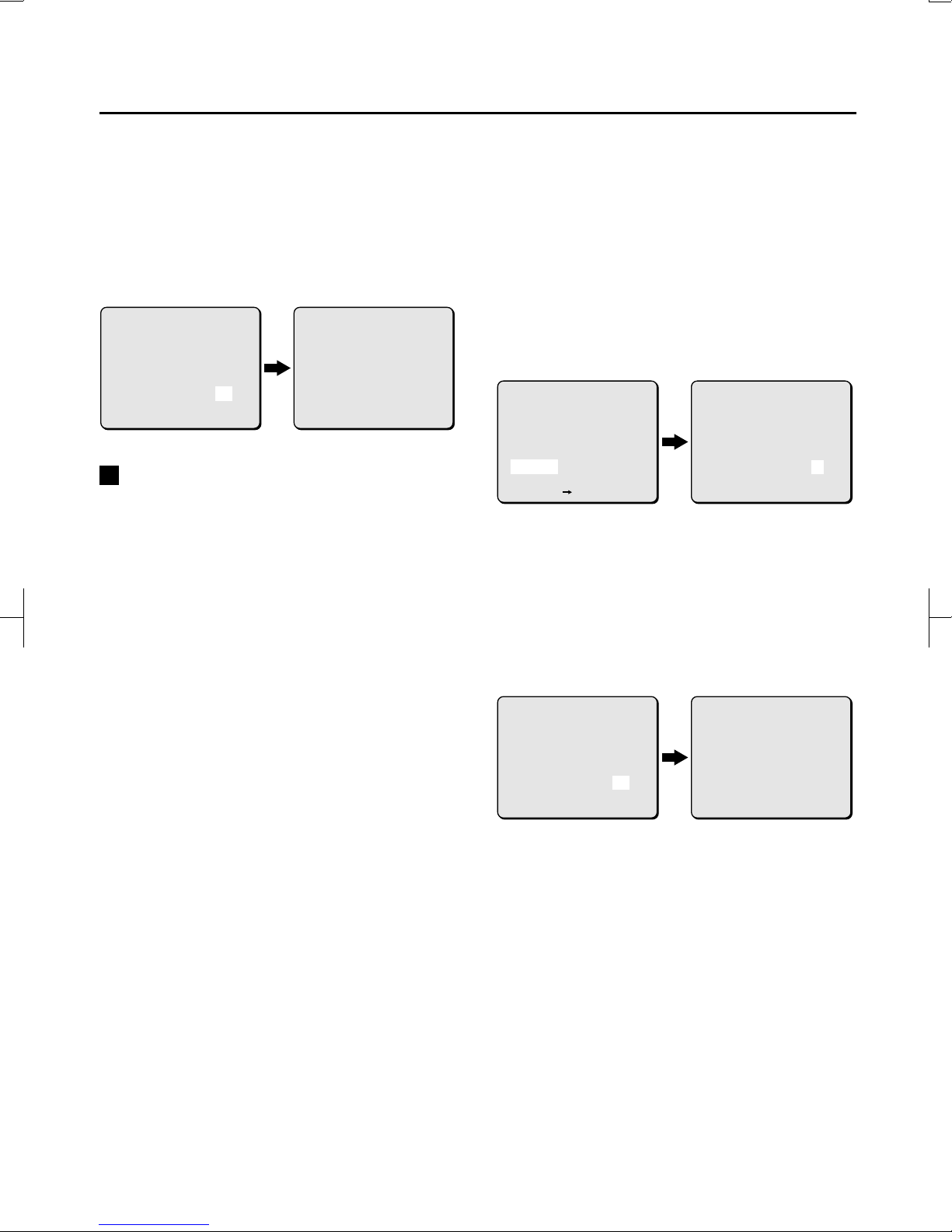
8Use the CURSOR (j or l) button to
select “INITIALIZE”, use the CURSOR (d or
c) button to select “YES”, then press the
SET button.
The hard disk will be initialized and the display
will return to the SETTINGS screen.
Selecting “NO” will bring up the H SET
screen.
Changing Alarm Capacity
The SPACE SET screen will appear when the disk
has been initialized or when POST ALARM images
have not been recorded on the PRE ALARM area of
the hard disk.
Alarm capacity can be changed in the SPACE SET
screen. However, if images have already been
recorded on the POST ALARM area of the hard
disk, the alarm capacity cannot be changed. In this
case, if capacity adjustment is desired, delete the
alarm images or initialize the hard disk, then adjust
the alarm capacity.
1Use the CURSOR (j or l) button to
select “SETTINGS”, then press the SET
button.
The SETTINGS screen will appear.
2Use the CURSOR (j or l) button to
select “HDD SET”, then press the SET
button.
The H SET screen will appear.
3Use the CURSOR (j or l) button to
select “SPACE SET”, then press the SET
button.
The SPACE SET screen will appear.
4Use the CURSOR button to reset the
capacity values in the alarm area.
Example:
1Set PRE ALARM for 3 hours, 30 minutes.
2Set POST ALARM for 2 hours, 45 minutes.
Values for “SUSPICION SHOTS” and
“ALARM TIME” will be set automatically.
Note: If a value is already recorded in the suspicion
area, the alarm capacity set time will be
different.
Use the CURSOR (j or l) button to
select “SET UP”, use the CURSOR (d or c)
button to select “YES”, then press the SET
button.
The alarm capacity will be changed and the
display will return to the SPACE SET screen.
Selecting “NO” will bring up the H SET
screen.
(HDD INITIALIZE)
<SUSPICION SHOTS: 1021 PCS>
<ALARM TIME 0 H 1 MIN>
PRE ALARM 0 H 30 MIN
POST ALARM 0 H 4 MIN
INITIALIZE YES
(HDD INITIALIZE)
<SUSPICION SHOTS: 1021 PCS>
<ALARM TIME 0 H 1 MIN>
PRE ALARM 0 H 30 MIN
POST ALARM 0 H 4 MIN
DO NOT POWER OFF!
INITIALIZING NOW!
(SPACE SET)
<SUSPICION SHOTS: 1021 PCS>
<ALARM TIME 0 H 4 MIN>
PRE ALARM 0 H 1 MIN
POST ALARM 0 H 30 MIN
SETUP NO
(HDD SET)
<SUSPICION SHOTS: 1021 PCS>
<ALARM TIME 0 H 4 MIN>
<PRE ALARM 0 H 1 MIN>
<POST ALARM 0 H 30MIN>
SPACE SET
INITIALIZE
[MENU] (SETTINGS)
(SPACE SET)
<SUSPICION SHOTS: 1021 PCS>
<ALARM TIME 4 H 1 MIN>
PRE ALARM 0 H 30 MIN
POST ALARM 0 H 4 MIN
SETUP YES
(SPACE SET)
<SUSPICION SHOTS: 1021 PCS>
<ALARM TIME 1 H 1 MIN>
PRE ALARM 0 H 30 MIN
POST ALARM 0 H 4 MIN
SETUP YES
DO NOT POWER OFF!
SETTING NOW!
L9EAA/WA (VA-LANC100) GB 2001, 9, 27
7 English
PC CONTROL SETUP (PC CONTROL SET)
The setup steps explained below are necessary for connection of the digital recording camera to a network or
for control of the camera from a computer directly connected with USB.
1Set the recording speed
2Choose the network settings
Set the recording speed
Set the recording frame rate that will be used when
the camera is connected to a network or USB. By
lowering the frame rate from the regular setting,
the camera is able to record even when connected
to the computer.
The following frame rates can be set for this
purpose.
●Pre Alarm recording rate (PRE ALARM RATE)
1Use the CURSOR (j or l) button to
select “SETTINGS”, then press the SET
button.
The SETTINGS screen will appear.
2Use the CURSOR (j or l) button to
select “PC CONTROL SET”, then press the
SET button.
The PC CONTROL SET screen will appear.
3Use the CURSOR (j or l) button to
select “RECORDING SPEED SET”, then
press the SET button.
The RECOR ING SPEE SET screen will appear.
4???Use the CURSOR (j or l) button to
select “PRE ALARM RATE”, then use the
CURSOR (d or c) button to select “1”.
3FPS: Records 3 image every second.
1FPS: Records 1 image every second.
After completion of the settings, press the
MENU button.
The PC CONTROL SET screen will reappear.
Keep pressing the MENU button until the
MAIN MENU screen appears.
SET
(RECORDING SPEED SET)
PRE ALARM RATE --- 3 FPS
CAMERA RECORDING FRAMERATE
UNDER PC CONTROL
(PC CONTROL SET)
RECORDING SPEED SET
NETWORK SET
PC CONTROL ----------- ON
RECORD STOP FROM PC -- OFF
[MENU] (SETTINGS)
(RECORDING SPEED SET)
PRE ALARM RATE --- 1 FPS
CAMERA RECORDING FRAMERATE
UNDER PC CONTROL
(RECORDING SPEED SET)
PRE ALARM RATE --- 3 FPS
CAMERA RECORDING FRAMERATE
UNDER PC CONTROL
L9EAA/WA (VA-LANC100) GB 2001, 9, 27
English 8
PC CONTROL SETUP (PC CONTROL SET)
Choose the network settings
The following settings are necessary to use the
camera on a network.
Note:
●Contact your network administrator to obtain
the appropriate IP address.
●???????????????? ???????????????
??????????????? ???????????????
A Set the IP Address, Subnet Mask
and Gateway
Example: The initial IP address 192.168.000.010
will be changed to 130.141.110.204.
1Use the CURSOR (j or l) button to
select “SETTINGS”, then press the SET
button.
The SETTINGS screen will appear.
2Use the CURSOR (j or l) button to
select “PC CONTROL SET”, then press the
SET button.
The PC CONTROL SET screen will appear.
3Use the CURSOR (j or l) button to
select “NETWORK SET”, then press the SET
button.
The NETWORK SET screen will appear.
4Use the CURSOR (j or l) button to
select “IP ADDRESS SET”, then press the
SET button.
The IP A RESS SET screen will appear.
Use the CURSOR button to select “1” from
the numeric pallet, then press the SET
button.
Use the same technique to select the
remaining numbers “30.141.110.204.” After
12 digits are selected, the cursor will
automatically move to “END”.
6Press the SET button.
The display will return to the NETWORK SET
screen.
(NETWORK SET)
IP ADDRESS : 192.168. 0. 10
SUBNET MASK: 2 .2 .2 . 0
GATEWAY : 192.168. 0. 1
USER ID : ADMIN
PASSWORD : ********
(PC CONTROL SET)
RECORDING SPEED SET
NETWORK SET
[MENU] (SETTINGS)
SET
(NETWORK SET)
IP ADDRESS : 192.168. 0.10
SUBNET MASK: 2 .2 .2 . 0
GATEWAY : 192.168. 0. 1
USER ID : ADMIN
PASSWORD : ********
SET
(IP ADDRESS SET)
IP ADDRESS : 192.168. 0. 10
01234 6789
END
(IP ADDRESS SET)
IP ADDRESS : 130.141.110. 10
01234 6789
END
(IP ADDRESS SET)
IP ADDRESS : 130.141.110.204
01234 6789
END
L9EAA/WA (VA-LANC100) GB 2001, 9, 27
9 English
7Use the same method to set the SUBNET
MASK and GATEWAY numbers.
8After completion of the settings, press the
MENU button.
The PC CONTROL SET screen will reappear.
Keep pressing the MENU button until the
MAIN MENU screen appears.
B Set the User ID (up to characters)
Example: The initial user ID “ADMIN” will be
changed to “USER1”.
1Use the CURSOR (j or l) button to
select “SETTINGS”, then press the SET
button.
The SETTINGS screen will appear.
2Use the CURSOR (j or l) button to
select “PC CONTROL SET”, then press the
SET button.
The PC CONTROL SET screen will appear.
3Use the CURSOR (j or l) button to
select “NETWORK SET”, then press the
SET button.
The NETWORK SET screen will appear.
4Use the CURSOR (j or l) button to
select “USER ID”, then press the SET
button.
The USER I SET screen will appear, allowing
entry of the password.
(NETWORK SET)
IP ADDRESS : 130.141.110.204
SUBNET MASK: 2 .2 .2 . 0
GATEWAY : 192.168. 0. 1
USER ID : ADMIN
PASSWORD : ********
(NETWORK SET)
IP ADDRESS : 192.168. 0. 10
SUBNET MASK: 2 .2 .2 . 0
GATEWAY : 192.168. 0. 1
USER ID : ADMIN
PASSWORD : ********
(PC CONTROL SET)
RECORDING SPEED SET
NETWORK SET
[MENU] (SETTINGS)
SET
(NETWORK SET)
IP ADDRESS : 192.168. 0.10
SUBNET MASK: 2 .2 .2 . 0
GATEWAY : 192.168. 0. 1
USER ID : ADMIN
PASSWORD : ********
L9EAA/WA (VA-LANC100) GB 2001, 9, 27
English 10
PC CONTROL SETUP (PC CONTROL SET)
Use the CURSOR button to select “U” from
the alphanumeric pallet, then press the
SET button.
Use the same technique to select the
remaining letters “SER1”. After 5 letters are
selected, the cursor will automatically move to
“END”.
6Press the SET button.
The display will return to the NETWORK SET
screen.
7After completion of the settings, press the
MENU button.
The PC CONTROL SET screen will reappear.
Keep pressing the MENU button until the
MAIN MENU screen appears.
C Set the Password
(up to 8 characters)
Example: The password will be set to
“CAMERA”.
1Use the CURSOR (j or l) button to
select “SETTINGS”, then press the SET
button.
The SETTINGS screen will appear.
?????????????????
????????????????????????
2Use the CURSOR (j or l) button to
select “PC CONTROL SET”, then press the
SET button.
The PC CONTROL SET screen will appear.
3Use the CURSOR (j or l) button to
select “NETWORK SET”, then press the SET
button.
The NETWORK SET screen will appear.
4Use the CURSOR (j or l) button to
select “PASSWORD”, then press the SET
button.
In the CHANGE PASSWOR -NETWORK screen,
the “OLD PASSWORD” field will be selected.
(USER ID SET)
USER ID :UDMIN
ABCDEFGHIJKLM
NOPQRSTUVWXYZ
01234 6789
BS END
(USER ID SET)
USER ID :USER1
ABCDEFGHIJKLM
NOPQRSTUVWXYZ
01234 6789
BS END
SET
(NETWORK SET)
IP ADDRESS : 192.168. 0. 10
SUBNET MASK: 2 .2 .2 . 0
GATEWAY : 192.168. 0. 1
USER ID : ADMIN
PASSWORD : ********
(PC CONTROL SET)
RECORDING SPEED SET
NETWORK SET
[MENU] (SETTINGS)
SET
(NETWORK SET)
IP ADDRESS : 192.168. 0.10
SUBNET MASK: 2 .2 .2 . 0
GATEWAY : 192.168. 0. 1
USER ID : ADMIN
PASSWORD : ********
(CHANGE PASSWORD-NETWORK)
OLD PASSWORD:
NEW PASSWORD:
VERIFICATION:
ABCDEFGHIJKLM
NOPQRSTUVWXYZ
01234 6789
BS END
SET
L9EAA/WA (VA-LANC100) GB 2001, 9, 27
11 English
Use the CURSOR button to select “END”,
then press the SET button.
The selected field will move from “END” to
“NEW PASSWORD”.
Note: ????? ????? ????? ????? ????? ?????
????? ????? ????? ????? ????? ?????
????? ????? ????? ????? ?????
6Use the CURSOR button to select “C”,
then press the SET button.
An asterisk will be displayed for the entered
character. Use the same technique to select
the remaining letters “AMERA”.
7Use the CURSOR button to select “END”,
then press the SET button.
The “******” (CAMERA) password will be
set, and the selected field will move to
“VERIFICATION”.
Verification checks for proper entry of the
desired password.
8Use the CURSOR button and the SET
button to enter “CAMERA” one more
time, and then select “END” again and
press the SET button.
“CAMERA” will be set as the password and
the NETWORK SET screen will reappear.
9After completion of the settings, press the
MENU button.
The PC CONTROL SET screen will reappear.
Keep pressing the MENU button until the
MAIN MENU screen appears.
(CHANGE PASSWORD-NETWORK)
OLD PASSWORD:
NEW PASSWORD:
VERIFICATION:
ABCDEFGHIJKLM
NOPQRSTUVWXYZ
01234 6789
BS END
(CHANGE PASSWORD-NETWORK)
OLD PASSWORD:
NEW PASSWORD:
VERIFICATION:
ABCDEFGHIJKLM
NOPQRSTUVWXYZ
01234 6789
BS END
SET
(CHANGE PASSWORD-NETWORK)
OLD PASSWORD:
NEW PASSWORD:
VERIFICATION:
ABCDEFGHIJKLM
NOPQRSTUVWXYZ
01234 6789
BS END
(CHANGE PASSWORD-NETWORK)
OLD PASSWORD:
NEW PASSWORD:
VERIFICATION:
ABCDEFGHIJKLM
NOPQRSTUVWXYZ
01234 6789
BS END
SET
SET
(CHANGE PASSWORD-NETWORK)
OLD PASSWORD:
NEW PASSWORD:
VERIFICATION:
ABCDEFGHIJKLM
NOPQRSTUVWXYZ
01234 6789
BS END
SET
(CHANGE PASSWORD-NETWORK)
OLD PASSWORD:
NEW PASSWORD:
VERIFICATION:
ABCDEFGHIJKLM
NOPQRSTUVWXYZ
01234 6789
BS END
L9EAA/WA (VA-LANC100) GB 2001, 9, 27
English 12
PC CONTROL SETUP (PC CONTROL SET)
Changing Set Entries
The 2 types of entry pallets are shown below.
Numeric Pallet (for addresses)
Alphanumeric Pallet (for User ID and Password)
Example 1: Changing the addresses from
“130141.110.204” to
“131.141.110.204” with the numeric
pallet.
1Use the CURSOR button to select the “í”
or “ü” field.
2Press the SET button as many times as
needed to place the shaded correction
cursor (ú) over the “T”.
3Use the CURSOR button to select “0” from
the numeric pallet, then press the SET
button.
4Use the CURSOR button to select “END”
from the numeric pallet, then press the
SET button.
(IP ADDRESS SET)
IP ADDRESS :130.141.110.204
01234 6789
END
(USER ID SET)
USER ID :USER1
ABCDEFGHIJKLM
NOPQRSTUVWXYZ
01234 6789
BS END
(IP ADDRESS SET)
IP ADDRESS :130.141.110.204
01234 6789
END
(IP ADDRESS SET)
IP ADDRESS :130.141.110.204
01234 6789
END
(IP ADDRESS SET)
IP ADDRESS :131.141.110.204
01234 6789
END
L9EAA/WA (VA-LANC100) GB 2001, 9, 27
13 English
Example 2: Changing the USER ID from
“UTER1” to “USER1” with the
alphanumeric pallet.
1Use the CURSOR button to select the
“íBS” (backspace) field.
Note: ????? ????? ????? ????? ????? ?????
????? ????? ????? ????? ????? ?????
????? ????? ????? ????? ?????
2Press the SET button as many times as
needed to place the shaded correction
cursor (ú) over the “T”.
3Use the CURSOR button to select “S” from
the alphanumeric pallet, then press the
SET button.
4Use the CURSOR button to select “END”
from the alphanumeric pallet, then press
the SET button.
To enter a space in your USER I or
PASSWOR , select the blank spot directly
below the letter “N”, then press the SET
button.
(USER ID SET)
USER ID :UTER1
ABCDEFGHIJKLM
NOPQRSTUVWXYZ
01234 6789
BS END
(USER ID SET)
USER ID :UTER1
ABCDEFGHIJKLM
NOPQRSTUVWXYZ
01234 6789
BS END
(USER ID SET)
USER ID :USER1
ABCDEFGHIJKLM
NOPQRSTUVWXYZ
01234 6789
BS END
L9EAA/WA (VA-LANC100) GB 2001, 9, 27
English 14
1AC6P1P2505--
L9EAA/WA (0901KP-BB)
SANYO Electric Co., Ltd.
Printed in Japan
L9EAA/WA (VA-LANC100) GB 2001, 9, 27

Other manuals for VA-LANC100

1

Other Sanyo Camera Accessories manuals

Sanyo Cadnica N-6PT User manual

Sanyo

Sanyo Cadnica N-6PT User manual

Sanyo KR-1100AEL Cadnica User manual

Sanyo

Sanyo KR-1100AEL Cadnica User manual

Sanyo N-110AA Cadnica User manual

Sanyo

Sanyo N-110AA Cadnica User manual

Sanyo Cadnica N-500AC User manual

Sanyo

Sanyo Cadnica N-500AC User manual

Sanyo UF103450P User manual

Sanyo

Sanyo UF103450P User manual

Sanyo KR-CH(2.5) Cadnica User manual

Sanyo

Sanyo KR-CH(2.5) Cadnica User manual

Sanyo Cadnica N-3000CR User manual

Sanyo

Sanyo Cadnica N-3000CR User manual

Sanyo VA-80EX User manual

Sanyo

Sanyo VA-80EX User manual

Sanyo KR-5/3MH Cadnica User manual

Sanyo

Sanyo KR-5/3MH Cadnica User manual

Sanyo N-250AAA Cadnica User manual

Sanyo

Sanyo N-250AAA Cadnica User manual

Sanyo Twicell HR-4/5FAUPT User manual

Sanyo

Sanyo Twicell HR-4/5FAUPT User manual

Sanyo UPF383450 User manual

Sanyo

Sanyo UPF383450 User manual

Sanyo N-1U Cadnica User manual

Sanyo

Sanyo N-1U Cadnica User manual

Sanyo Cadnica N-700AAC User manual

Sanyo

Sanyo Cadnica N-700AAC User manual

Sanyo CR17335E-R User manual

Sanyo

Sanyo CR17335E-R User manual

Sanyo Cadnica N-50AAAS User manual

Sanyo

Sanyo Cadnica N-50AAAS User manual

Sanyo UF653450R User manual

Sanyo

Sanyo UF653450R User manual

Sanyo Twicell HR-4/5SCU User manual

Sanyo

Sanyo Twicell HR-4/5SCU User manual

Sanyo N-2000CK Cadnica User manual

Sanyo

Sanyo N-2000CK Cadnica User manual

Sanyo Cadnica KR-2000C User manual

Sanyo

Sanyo Cadnica KR-2000C User manual

Sanyo UPF385374 User manual

Sanyo

Sanyo UPF385374 User manual

Sanyo N-190N Cadnica User manual

Sanyo

Sanyo N-190N Cadnica User manual

Sanyo KR-900AAEC Cadnica User manual

Sanyo

Sanyo KR-900AAEC Cadnica User manual

Sanyo UF553450L User manual

Sanyo

Sanyo UF553450L User manual

Popular Camera Accessories manuals by other brands

Kodak PROFESSIONAL PORTRA 160NC Technical data

Kodak

Kodak PROFESSIONAL PORTRA 160NC Technical data

Nikon FTZ manual

Nikon

Nikon FTZ manual

Ikelite 6241.81 Supplemental instructions

Ikelite

Ikelite 6241.81 Supplemental instructions

CARVIN B400 installation instructions

CARVIN

CARVIN B400 installation instructions

Lowepro C840 Compatibility guide

Lowepro

Lowepro C840 Compatibility guide

EmergoPlus POWERXTREME X20 LiFePO4 user manual

EmergoPlus

EmergoPlus POWERXTREME X20 LiFePO4 user manual

SLIK SH-736HD operating instructions

SLIK

SLIK SH-736HD operating instructions

Bowens Ringflash Pro Brochure & specs

Bowens

Bowens Ringflash Pro Brochure & specs

Star Battery Holder T4 user manual

Star

Star Battery Holder T4 user manual

Panasonic AU-VEXT1G operating instructions

Panasonic

Panasonic AU-VEXT1G operating instructions

Square Jellyfish Jelly Legs micro tripod user manual

Square Jellyfish

Square Jellyfish Jelly Legs micro tripod user manual

Nauticam NA-D7100 instruction manual

Nauticam

Nauticam NA-D7100 instruction manual

Isotta ALPHA 7RIV instructions

Isotta

Isotta ALPHA 7RIV instructions

Philips LR1PB2C Specification sheet

Philips

Philips LR1PB2C Specification sheet

Logitech CIRCLE 2 quick start guide

Logitech

Logitech CIRCLE 2 quick start guide

iOptron AllView Pro instruction manual

iOptron

iOptron AllView Pro instruction manual

Cactus RF60 user manual

Cactus

Cactus RF60 user manual

Triton T20HCB Operating and safety instructions

Triton

Triton T20HCB Operating and safety instructions

manuals.online logo
manuals.online logoBrands
  • About & Mission
  • Contact us
  • Privacy Policy
  • Terms and Conditions

Copyright 2025 Manuals.Online. All Rights Reserved.