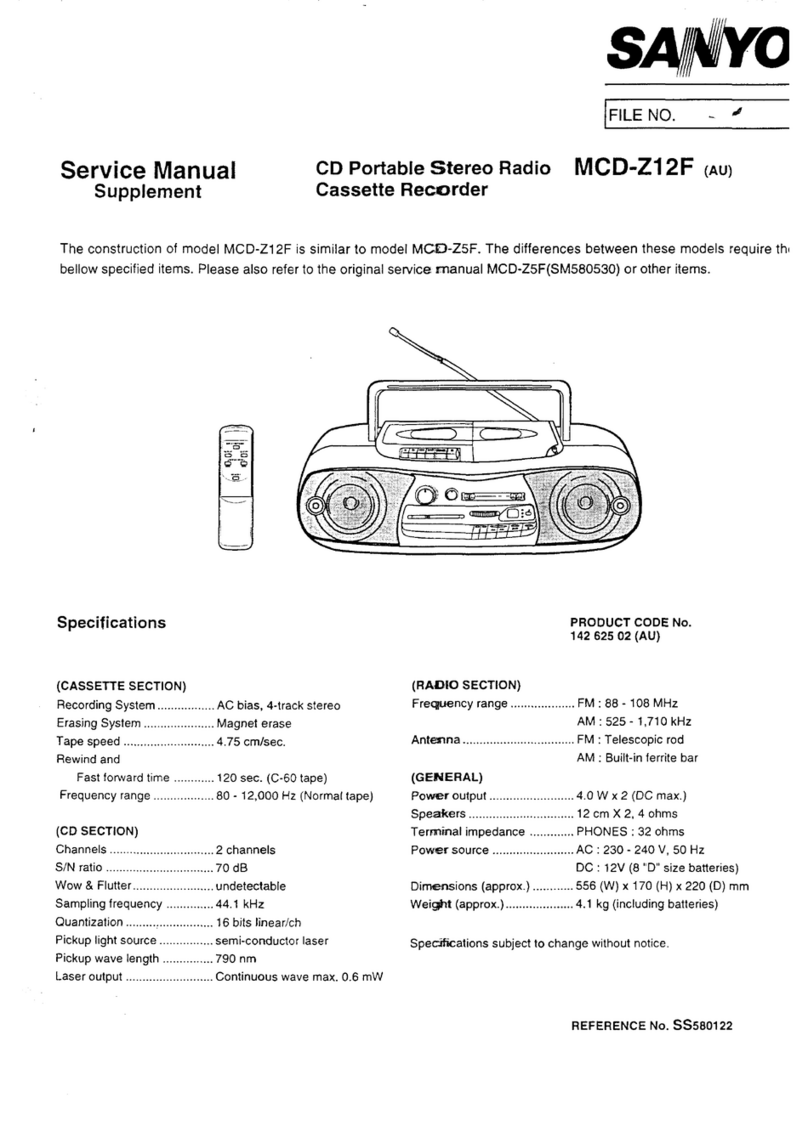
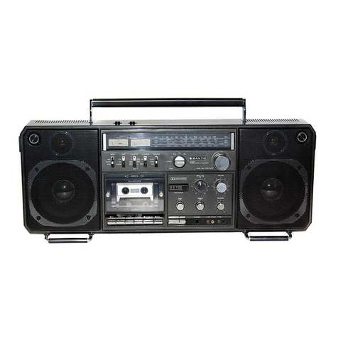
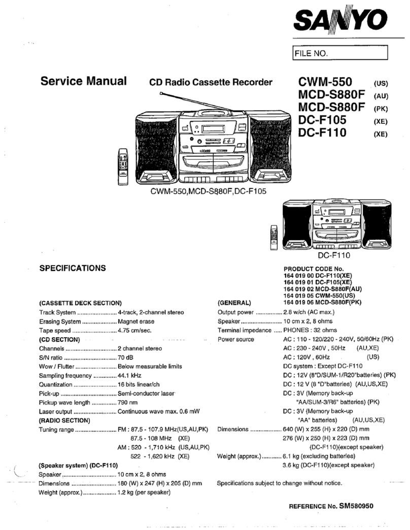
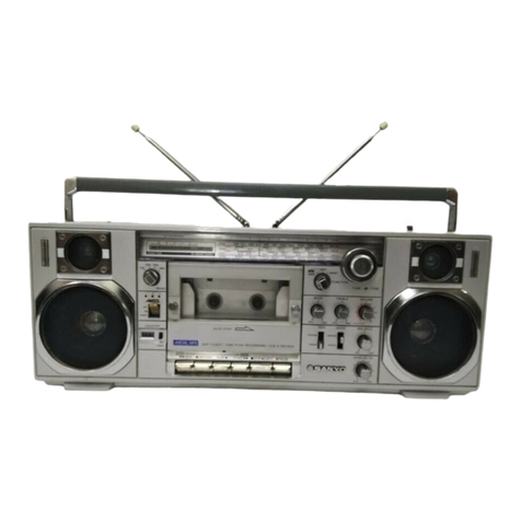
Sanyo M-W2K User manual

SERVICE
MANUAL
STEREO
RADIO
DOUBLE
CASSETTE
RECORDER
SPECIFICATIONS
Power
Source
Hum
&
NOIS@
ooo.
ceee
ee
eeeeeteeees
Less
than
50
dBs
AG
Sill
heaters
Mick
ott
his
120/2
10/240V
Crosstalk
ie...)
anand
toate
Better
than
45
dB
(50/60Hz)
Channel
Separation
..........
Better
than
45
dB
DG
oicovs
oth
essa
tteorteesie
ean
egsonsses
Stove
vehe
ze
QV
(D
Cell
x
6)
Terminal
Impedance
Output
POW
.....e
cee
cttet
cece
ere
eeeneeeees
2.0
W
x
2
(10%)
MiGaicentantinitaniaaderetace.
600
ohm
Power
Consumption
............cee
cece
15
W
SPCAaK
Cis
eises
cc
dorslee
ease
3
ohms
Recording
System
......cccccceeee
AC
Bias
Headphone...
8
ohms
Erasing
SyStem
......cccccceeeseeeeeeneteeeerees
AC
Erasing
Frequency
Range
Tape
Gu
dbaton:
4.75
cm/sec.
+3%
MW
ricinus
akeaies:
520
—
1,620
kHz
Fast
Forward
Time@..........
cece
110
sec.
(C-60
cassette)
SWiliieen
el
ee
naar
aad
2.3
—
7.0
MHz
REWINd
Timm
.........
ses
eeesceesereceeseserseeeeseees
110
sec.
(C-60
cassette)
SW
2a
estate
ine
ene
edi
7.0
—
22.0
MHz
Wow
&
Flutter
occ
cece
reeeeeteeseees
0.3
%
WRMS
EMiste
ee
Sine
det
88
—
108
MHz
Frequency
ReSpONnSe.......
cece
100
—
8,000
Hz
Input
Sensitivity
Signal
to
Noise
Ratio...
ccc
Better
than
40
dB
WMG
tianie
Ccvatt
olan
0.3
mV
-
NOTE:
Specifications
are
subject
to
change
without
notice.
a
WM-10144

ALIGNMENT
PROCEDURES
FM
ALIGNMENT
Standard
test
frequency
400
Hz
and
deviation
22.5
kHz
oan
Connections
Frequency
fanine
Dial
fad
:
:
F
;
justment
emarks
Alignment
OUTPUT
of
Signal
Séiting
Generator
‘
:
Connect
input
Calibration
Place
ouptut
of
:
terminal
of
gene-
1
of
gene-scope
on
10.7
MHz
|
Lowest
end}
11
and
T2
scope
to
IF
TP1
TP2
10.7
MHz
e
marker
fide
oS
fe
oo
|
2
Calibration
Connect
signal
Connect
VTVM
with
87.2
MHz
L3
Obtain
sine-curve
of
generator
to
antenna
4
ohm
dummy
load
and
maximum
arnplitude.
Tuning
Range
}
terminal
(J1)
and
oscilloscope
to
;
=
3
tiieugh
dummy
speaker
terminal.
108.5
MHz
|
Highest
end
CT2
(PVC)
4
|
Adjustment
|
antenna.
80
MHz
|
90
MHz
L2
ai
(|
of
a
5
Tracking
106
MHz
106
MHz
CT1
(PVC)
6
Repeat
the
above
adjustments.
fer
te
*»
Use
a
screwdriver
with
plastic
grip
for
all
adjustment.
MW
ALIGNMENT
Standard
test
frequency
400
Hz
and
modulation
30%
at
AM
Connections
Frequency
Step
Alignment
of
Signal
que
hi
Adjustment
Remarks
OUTPUT
Generator
Setting
Calibration
Obtain
symmetrical
curve
1
of IF
:
;
and
maximum
am@ii
tude.
for
AM
Place
output
of
enkcen
ae
[ea
Tagusient
|
cal
tee
to
gene-scape
to
455
kHz
|
Lowest
end
T3
and
T4
hax
7
2
of
P
TP2
|
IF
Gain
ee,
po
LS
Obtain
sine-wave
o:
400
Hz
Calibration
Connect
standard
515
kHz
a
of
loop
antenna
to
Connect
VTVM
with
'
and
maximum
ampli
tude.
4
Tuning
Range
|
output
of
signal
4
ohm
dummy
load
1660
KHz
|
Highest
end
CT5
generator.
and
oscilloscope
to
La
;
5
Adjustment
|
Place
bar
antenna
speaker
terminal.
600
kHz
600
kHz
ishy
ante
661)
|
Max
|
of
60
cm
away
from
:
6
Tracking
loop
antenna.
1400
kHz
|
1400
kHz
CT6
7
Repeat
the
above
adjustments.
FM
MPX
ALIGNMENT
Connections
Tuni
;
uning
Dial
:
P
Le
Alignment
INPUT
OUTPUT
Setting
Adjustment
Remarks
Connect
TP2
Connect
Frequency
|
;
to
the
GND.
counter
to
TP3
—
SVR1
eee
kHz
on
the
frequency
SW1
ALIGNMENT
——
Frequency
of
Signal
Generator
Connections
;
Tuning
Dial
Setting
Alignment
Adjustment
Remark;
OUTPUT
|
Obtain
sine-wave
9
400Hz
and
maximum
amp
tude
Calibration
of
Tuning
Range
Lowest
end
L6
CT3
(PVC)
LQ
Connect
VTVM
with
eee
4
ohm
dummy
load
es
terminal
(J4)
through
and
oscilloscope
to
djustment
dummy
antenna
Ext.
speaker
of
terminal.
Tracking
Connect
signal
generator
to
Highest
end
7.4
MHz
2.5
MHz
2.5
MHz
6.5
MHz
Repeat
the
above
adjustments.
j
|
6.5
MHz
§
|

PARTS
LIST
(CASSETTE
MECHANISM
A)
K
1
Visser
Nie
PART
No.
DESCRIPTION
oe
PART
No.
DESCRIPTION
a
oO.
ae
;
:
2
CASSETTE
MECHANISM
(R-S97123)
36
pues
Solas
Eject
:
1
|
AS07485
Head,
Dummy
4
ATN-18001
103A
Slide
lever,
Eject
4
:
Screw,
Bind
Hd.,
(+
.—),
2x7mm
E-ring,
Metal,
3.2mm
:
Screw,
Pan
Hd.,
(+,.-),
2x7mm
1
ATN-180001503
Chassis
assembiy
1
4
Screw,
Bind
Hd.,
(+,-),
2x7mm
1
Screw,
Round
Hd.,
HIOS,
2.6x4mm
5
5
R-S07484
Head,
Record/Play
:
ATN-17000977
Shaft,
Push
button
lever
:
6
ATN-18000403
Spring
ATN-17000805
Bracket,
Side
7
ATN-180004301
Pinch
roller
assembly
1
ATN-18000316
Panel,
Head
:
8
ATN-17152015
Stopper,
Pinch
roller
arm
1
ATN-18000309
Spring,
Head
panel
9
ATN-97430000
P
washer
cut,
1.6mmx3.8mmx0.3mmt
2
ATN-18000305
Head
base
1
ATNBOOUEeS
Sorin
acct
i
ATNeTac0GeG
meee
2.4mmx7mmx0.2mmt
11
at
Pring
‘
see
:
12
ATN-12001201
Special
screw
;
3
ATN-93120000
Washer,
2.1mmxSmmx0.4mmt
1
13
ATN-18000934
Push
button
base,
Right
1
ATN-14400315
Spring
:
1
14
ATN-97
180000
Special
screw
i
1
ATN-180003303
Plate
assembly,
Sensing
:
15
ATN-93610000
Flat
washer,
Nylon,
1.8mmxSmmx0.5mmt
4
ATN-18000507
Spring
:
16
ATN-18000935A
Push
button
base,
Left
1
ATN-180005302
Supply
reel
assembly
d
17
ATN-180006301
RF
pulley
arm
assembly
1
ATN-18000610
FF
gear
ae
18
ATN-94210000
P
washer
cut,
1.2mmx3mmx0.25mmt
2
ATN-18000201
Lever,
Record
satety
:
19
ATN-18000605
Take-up
roller
assembly
:
a
eos
aaa
ve.
ae
20
ATN-18000608
Spring
ubber,
Mo
3
21
ATN-180006501
Arm
assembly,
Take-up
roller
1
ATN-MSW-1275ASNK
Leaf
switch
i
22
|
ATN-18000609
Collar
1
ATN-18000957
Spring
]
23
Tap.
Screw,
Pan
Hd.,
C-tight.
2x4mm
|
1
Tap.
Screw,
Pan
Hd..
P-tight,
2x6mm
|
:
24
|
ATN-180007303
Flywheel
assembly
[4
ple
be
lee
eort
!
:
1
:
pring
25
ATN-18001007
Main
belt
Tap.
Screw,
Pan
Hd.,
C-tight,
2x6mm
'
26
ATN-1
2000906
Flywheel
plate
1
ATN-18000903
Spring
'
;
27
ATN-18000712
Holder,
Flywheel
|
‘ATN-9776000
Flat
washaes
Nvlony
yi
;
60000
at
washer,
Ny
28
i
Tap.
Screw,
Bind
Hd.,
P-tight,
2x9mm
1
>
OSmmx8mmx0.5mmt
29
ATN-180009320
Push
button
actuator
assembly
1
ATN-18000707
Spring
1
30
ATN-18000917
See
Actuator
,
ATN-18000930
Lever,
Stop
button
31
ATN-18000919
pring
ATN-18000929
Lever,
FF
button
oe
ATN-17000921
Shaft,
Actuator
d
ATN-18000928
Lever,
RWD
button
1
“
ATN-EG-500AD-9B
Motor
ATN-18000943
Lever,
Play
bution
i
on
Screw,
Round
Hd.,
HIOS,
2.6x5mm
3
ATN-17001031
Bracket,
Motor
:
35
Screw,
Pan
Hd.,
2.6xS5mm
1
ATN-18001001
Pulley,
Motor
PARTS
LIST
(CASSETTE
MECHANISM
B)
NOTES:
1.
PART
No.
Part
orders
must
contain
Model
Number,
Part
Number
and
Description.
2.
Ordering
quantity
of
screws
and/or
resistors
must
be
multiple
of
10
pcs.
DESCRIPTION
CASSETTE
MECHANISM
(R-S97124)
ATN-18000316
ATN-18000309
ATN-18000305
ATN-18001404
R-S07257-1
ATN-180004301
ATN-17152015
ATN-97430000
ATN-180005301
ATN-18000934
ATN-97
180000
ATN-93610000
ATN-18000935A
ATN-180006501
ATN-18000605
ATN-94210000
ATN-18000608
ATN-12001201
ATN-58809
10
ATN-18001021
ATN-18001001
ATN-EG-500AD-9B
ATN-12000906
ATN-180007
12
ATN-18201032
ATN-18000958
ATN-18000917
ATN-180009505
ATN-18000919
ATN-17000921
ATN-15101
103
“NOTES:
1.
2*
Ordering
quantity
of
screws
and/or
resistors
must
be
multiple
of
10
pcs.
Head
pane!
Head
panel
spring
Head
base
RC
spring
E-ring,
metal,
3.2mmd
Erase
head
Screw,
Bind
Hd.,
(+
,-),
2x7mm
Screw,
Pan
Hd.,
(+.-),
2x7mm
Pinch
roller
assembly
Pinch
roller
arm
stopper
P
washer
cut,
1.6mmx3.8mmx0.3mmt
Take-up
reel
assembly
Push
button
base
right
Special
screw
Flat
washer,
Nylon,
1.8mmx5mmx0.5mmt
Push
button
base
left
Take-up
rolier
arm
assembly
Take-up
roller
assembly
P
washer
cut,
1.2mmx3mmx0.25mmt
Spring
Special
screw
Motor
rubber
Screw,
Round
Hd.,
HIOS,
2.6x4mm
Motor
Dracket
Motor
pulley
Motor
Flywheel
plate
Fiywheel
holder
Tap.
Screw,
Bind
Hd.,
P-tight,
2x9mm
Pause
lever
stopper
Spring
Actuator
shaft
Push
button
actuator
assembly
Spring
Actuator
shaft
‘
Screw,
Round
Hd.,
HIOS,
2.6x56mm
Screw,
Pan
Hd.,
2.6x5mm
Eject
collar
Sa
Ge
er
wa
ge
er
ne
nen
ere
Mew
won
yoOwonmoins
PART
No.
DESCRIPTION
Q'ty
ATN-18001123
ATN-18001103A
ATN-17000810
ATN-17000977
ATN-180001503
ATN-180003305
ATN-14400315
ATN-93120000
R-S07373-6
ATN-18000405
ATN-180005302
.
ATN-18000507
ATN-180006
10
ATN-18000509
ATN-18000201
ATN-1
000104
ATN-18000926
ATN-18000903
ATN-18000957
ATN-18000609
ATN-18000707
ATN-180007303
ATN-18001007
ATN-180006304
ATN-12221702
ATN-180009504
ATN-18000930
ATN-18000929
ATN-18000928
ATN-18000943
ATN-17000845
ATN-18000905
ATN-18000907
ATN-MSW-1275ASNK
Spring
Eject
slide
lever
Side
bracket
right
Push
button
lever
shaft
Chassis
assembly
Sensing
plate
assembly
Spring
Washer,
2.1mmx5mmx0.4mmt
Record/Play
head
Spring
Supply
ree!
assembly
Spring
FF
gear
Spring
:
Record
safety
lever
Pack
spring
REC
button
lever
Spring
Spring
Tap.
Screw,
Pan
Hd.,
C-tight,
2x6mm
Tap.
Screw,
Pan
Hd.,
C-tight.
2ximm
Collar
Tap.
Screw,
Pan
Hd.,
C-tight,
2x4emm
Fiat
washer,
Nyton,
2.4mmx7mmx0.5mmt
Spring
Flywheel
assembly
Main
belt
RF
pulley
arm
assembly
Pause
lever
Pause
button
lever
assembly
Stop
button
lever
FF
button
lever
RWD
button
lever
Play
button
lever
Bracket
Spring
Spring
Leaf
switch
Tap.
Screw,
Pan
Hd.,
P-tight,
2xgenm
Part
orders
must
contain
Model
Number,
Part
Number
and
Description.
Sok
RO
Se
ROD
ee
ea
ee
Se
a
nn
a
Or
ee
es

ALIGNMENT
PROCEDURES
SW2
ALIGNMENT
S
Al
ee
Be
puntiig:
Dit
Adjustment
Remarks
tep
ignment
:
INPUT
OUTPUT
Generation
Setting
Js
A
:
400
H
1
Calibration
Connect
signal
Connect
VTVM
with
&
OME.
Koweet
ead
L7
Obtain
sine-wave
of
400
Hz
of
generator
to
4
ohm
dummy
load
4
and
maximum
amplitude.
i
.
:
;
High
2
{Tuning
Range
|
antenna
terminai(J1)
|
and
oscilloscope
to
23.2
MHz
ighestend
CT
4(PVC)
|
j ;
k
3
Adjustment
|
through
dummy
Ext
speaker
7
MHz
7
MHz
L10
Max
of
antenna.
terminal.
2224
4
Tracking
21
MHz
21
MHz
—
—
5
Repeat
the
above
adjustments.
HEAD
AZIMUTH
ADJUSTMENT
1.
Load
test
tape
MTT-114
in
the
cassette
case.
Tt
2.
Connect
a
VTVM
to
the
LEFT
EXT
SP
jack,
and
another
VTVM
to
the
RIGHT
EXT
SP
jack.
3.
Place
the
FUNCTION
SELECT
switch
in
the
TAPE
MODE
and
playback.
VTVM
(MAX.)
2:
4.
Adjust
the
head
azimuth
adjusting
screw
for
maximum
playback
output
on
the
VTVM's.
MECHANICAL
ADJUSTMENT
Can
not
be
done.
3.
4,
Frequency
counter
3kHz
+
15Hz
4
ohm
(2W)
Dummy
load
=
see
TAPE
SPEED
ADJUSTMENT
Load
test
tape
MTT-111
which
has
been
recorded
with
a
3,000
Hz
test
signal
Connect
the
frequency
counter
to
the
LEFT
EXT
SP
jack
in
parallel
with
the
VTVM
SPEAKERS
R
L
Place
the
tape
deck
in
the
play
made.
Adjust
the
trim
pot
tn
the
motor
for
2,985
Hz
to
3,015
Hz
reading
on
the
frequency
counter.
eo
a
ETE
|
Hh
MEASUREMENT
METHOD
REMARKS
Hook
the
spring
gauge
to
pinch
roller
metal
and
pull!
it
away
Pinch
roller
300-500
from
the
capstan.
See
Playback
adjustment
gr
Measure
the
pressure
the
moment
the
pinch
roller
comes
in
figure
1
contact
with
the
capstan
and
the
pinch
roller
starts
rotating.
Mount
the
cassette
torque
meter
in
the
same
way
as
the
Take-up
torque
4070
.
Playback
cassette
tape.
_
adjustment
g.cm
The
take-up
torque
is
shown
on
the
torque
meter.
Fast-forward
and
fa
FF
Mount
the
cassette
torque
meter
in
the
same
way
as
the
|
rewinding
torque
or
55150
cassette
tape.
_
;
adjustment
rewind
gcM
|
The
F.Forward
and
rewind
torque
is
shown
on
the
torque
mete:
Wow
and
flutter
p
of
p
’
|
a
JIS
weighted
ayback
0.1%
lay
back
3kHz
(tset)
tape
and
read
with
the
wow
meter.
Pinch
roller
—
Spring
gauge
Fig-14

EXPLODED
VIEW
(CASSETTE
MECHANISM
A)

SCHEMATIC
DIAGRAM
1C1
TA7358P
D2
15553
Di
0S442
1C2
TA7T640
AP
IC3_
LA3361
D3
SLP-141B
a
BAND
SELECT
51-8,,,
|
[FM
STEREO
LED
61
OOOOOOOOO!
7°
IC
VOLTAGE
(V)
ROD
ANT.
1€101
S2
FM
MODE
1C102
PLAY
R9
220K
C19
47/63V
O
MONO
OISTEREO
1
|
51
MOOOOOOO
Pa
oaniies
=)
R13
SaaeeaaeTRSME
EA
(
r)
r
5.6K
otal
Siar
(]s*
om
wm
uw
oy
at
a
Sr
are
=
*
SP4
a
it
SP1
cvs
R141
56K
VRIO1
VR1I02
VRIO3
Ls
MECHANISM
A
pac
raev]
|
—
CS2
}CP2
5
5
ae
EXT.
SP
L-CH
3
Se
R142
}
R202
‘|
7
JK3
K
os
a”
!
ia
F
a
ts
$3-3
FUNCTION
z
©
OUBBING
2.6V
R165
114
=
&
\
270K
BA
Isov
e2h3
<
Bech
x
gS
8
t
‘cre
|
3
,
es
PLAY
HEAD
Segue
a
|
HS
=<
Sy
|-—00
mi
he
EADPHO
oT
S
&
5
veoh
\eF
2103
JKS
Saem
2%
0.2v
=
R143)
“D301
RDS.1EB3
180
0302
SLP-167B
EXT.
MIC
>
L-CH
ze
!
'
EXT.
SP
R-CH
©
JK4
=
8
FUNCTION
|
J
‘<3
“I
C140
S36
J
oe,
;
$
uk
DUBBING
z
Oy
TAPE
ea
801.802.803.804
051350
reals
@O®
@]
8
Fe)
AC
120V/
210V/240V
5016
OHz
1
c172
tt
3300/16V
a
DQ
R119
560
R136
22K
me
804
.01|
C803
01
8
0803
*
dy
a
=)
of
©
REC
a
J101
d,
42801
Sa
ipa
=
R228
s
$48
.
1021
Js802
~
a
a
a
O-OD
Sg
n
R/P
SW
S
O90
3
EXT.
MIC
O
OUBBING
=
=
~
4
=
FUNCTION
s7
R-CH
$3-5
AC/DC
SELECT
JK2
R136
O
OUBBING
=
22K
Q104
C118
47/6.3V{R121
1M
C123
47/6.3V
TS7NCV
&70/10V
E
S4-3
RIP
SW
PLAY
D402
R404
22K
C401
220/6.3V
R130
1K
0103
RECORD/PLAY
HEAD
C121
R125
220P
47K
C221
R225
PMOTOR
2
R430
100K
MECHANISM
CONTROL
-
ee
TobL0a
£09
Lid
Dekaz
3.
$0734
C101
LA3160
Q103
@101.201.102.202
104.105
Di06
GZA6.BY
D401.
402.403.
404.
405.
406.408.409.410
0S442
Q401
254608
Q403.409
2
ene
Meat
2SC536
2501012
280734
D101.102.201,
202.104.105.107
0S442
se
D407
RDS.1EB3
-
Q404.405.
406.408,
410.402
250536
ERASE
HEAD
seach
ares

WIRING
DIAGRAM
|
|
MAIN
P.C.B.
BAe
eg
a,
————_]
fra
POWER
P.C.B.
Bottom
—
oe
bape!
oan
AC
CORD
-
L-CH
CONDENCER
MIC
O
~
BATTERY
:
2.
TE
e235:
C2
Q:;
Ose:
fexereye
eta
:
abs
&
r,
oe
-37
2
Sage
ER
Pett
freed
greterien
Gert
sates
pactopi
pleterky
Me
AS
ta
Le
QOeHOe@oI!04
DOPOD
®
8009
Iga
-50
OOOO:
ies
le
HO
R-CH
CONDENCER
MIC
LED
P.C.B.
Bottom
fg
230
ee
Cl
O
FM
STEREO
LED
P.C.B.
Bottom
CS
|
2

JED
VIEW
(CABINET
&
CHASSIS)
PART
No.
DESCRIPTION
DESCRIPTION
PACKAGE
PARTS
R-317983
Back
lid
: ;
12
R-1571826
Coil
spring,
Battery
terminal
(+).
(-)
ee
piiroroany
cusnions
Seta
13
R-1571526
Coil
spring,
Battery
termina!
(-)
R-4175136
R-4076905
R-357742
R-4775030
Styro-foam
cushion,
Set
left
Individual
carton
Polyethylene
bag,
Set
Caution
tag
14
R-237214
Battery
terminal
(+)
15
R-317921-1
|
Battery
lid
16
R-1274530
Bracket,
Rod
antenna
17
R-S873098
Handle
assembly
CLA
TA
cals
eck,
kt
kt
pe
ACCESSORY
PARTS
18
R-3975565
‘|
Bracket,
Handle
R-4777434
|
Instruction
manual
1
.
Screw,
Washer
Hd.,
B-tight,
3x8
AC
cord
mtg.
R-S07193-1
R-S27556
R-S27556-2
CABINET
APPEARANCE
PARTS
R-A700461
R-A79873
R-A79874
R-S873103
Magnetic
tape
:
7
Screw,
Washer
Hd.,
B-tight,
3x12
Z
Power
trans
mtg.
Screw,
Washer
Hd.,
B-tight
,
3x10
S
POWER
P.C.B.
mtg.
Screw,
Pan
Hd.,
B-tight,
3:30
7
Back
lid
mtg.
CHASSIS
MECHANICAL
PARTS
R-317988
Bracket,
P.C.B.
Screw,
Pan
Hd.,
3x8
Screw,
Pan
Hd.,
P-tight,
3:
12
Pointer
Pulley
Drum
\
Screw,
Pan
Hd.,
2.6x6
jor|
Plug
adaptor
Front
panel
assembly
Door
assembly,
Cassette
A
Door
assembly,
Cassette
B
Dumper
Screw.
Pan
Hd.,
P-tight,
3x10
Screw,
Pan
Hd.,
P-tight,
3x8
Bracket,
Case
Torsion
spring,
Cassette
case
Net,
Woofer
Cap.
Tweeter
Knob,
FINE
TUNING
Knob,
TUNING
4.5
turn
R-1274852
R-1572108
R-1274854
R-3975566
R-3975556
R-3975557
R-3975887
R-357398
R-3974914
a
os
a
AD
NN
O=7
=
MMM
HA
aA
a
a
a
NOTE
Pointer:
Lowest
end
and“O”
point
at
same
time
R-3975543-1
|
Knob,
TONE/BALANCE/VOLUME
R-157189
Coil
spring
Sing.
BOOK
eamin
teliective
Seamm,)
.
;
-
NOTES:
1.
Part
orders
must
contain
Model
Number,
Part
Number
and
Description.
we
2,
Ordering
quantity
of
screws
and/or
resistors
must
be
multiple
of
10
pcs.
—10—
mee
pee

PARTS
LIST
(CONTINUED)
ire
Ref.No.
PART
No.
DESCRIPTION
Q'ty
Dey
Ref.No
PART
No.
DESCRIPTION
O'ty
C111,241
SBL
ceramic,
0.0015mfd,
2
C406
560
k
ohm
1
+10%,
25V
R407
1k
ohm
1
C114,214,143,243
SBL
ceramic,
0.022mfd,
+10%,
25V}
4
R408,422,423
560
ohm
3
C119,219
SBL
ceramic,
0.0012mfd,
2
R411,416
1.8k
ohm
2
+10%,
25V
R413,414,418,419
33
k
ohm
4
C120,220
SBL
ceramic,
0.0033mfd,
2
R420,430
100
k
ohm
2
+10%,
25V
R425
10
k
ohm
1
C19,40,103,203,113,213
|
Electrolytic,
100mfd/6.3V
6
R427
47
k
ohm
1
C20,43,46,47,50,51,115,
|
Electrolytic,
1mfd/S0V
14
R428,430
100
k
ohm
2
215,141,142,144,244,
R410,415
4.7
ohm,
4,W,
+5%
z
108,208
R431
68
k
ohm
1
C37,125,118,122,140,
Electrolytic,
47mfd/6.3V
9
CAPACITORS
148,248,107,123
C401
Electrolytic,
220mfd/6.3V
1
C38
Electrolytic,
22mfd/10V
1
C402
Electrolytic,
4.7mfd/25V
1
C44
Electrolytic,
0.47mfd/SOV
1
C403,404
Electrolytic,
220mfd/16V
2
C45
Electrolytic,
2.2mfd/50V
1
C405
Electrolytic,
0.1
mfd/50V
1
C101,201
Electrolytic,
4.7mfd/25V
2
C406
|
Electrolytic,
22mid/10V
1
C105,117
Electrolytic,
220mfd/6.3V
2
106,206,
112,212
Electrolytic,
10mfd/16V
4
POWER
P.C.B.
ASSEMBLY
C146,246
Electrolytic,
100mfd/10V
2
R-A700150
|
Circuit
board
assembly,
Power
i
C149,249
Electrolytic,
470mid/10V
2
PT1
R-W770333-7}
Power
transformer
1
C150
Electrolytic,
100mfd/16V
1
S7
R-$47973
Slide
switch,
AC/DC
1
C151
Electrolytic,
47mfd/16V
1
S8
R-S47860-1
|
Rotary
switch,
1
C170
Electrolytic,
47mfd/10V
1
VOLTAGE
SELECTOR
C171
Electrolytic,
470mfd/10V
1
R-237188
Eyelet
lug
2
Ci72
Electrolytic,
3300mid/16V
1
R-25727
Socket
pin
2
C160
Electrolytic,
47mfd/SOV
1
SEMICONDUCTORS
C128,228
Electrolytic,
0.22mfd/SOV
2
Diode,
DS135D
é
C52,53
SBL
ceramic,
0.0056mfd,
2
CAPACITORS
410%,
25V
Ceramic,
0.01mfd,
+80
—20%,
1
8
C126,226
SBL
ceramic,
0.033mfd,
+20%,
25V|
2
50V,
Z
LED
P.C.B.
ASSEMBLY
CASSETTE
MECHANISM
50
R-A700148
|
Circuit
board
assembly,
1
R-S97124
Cassette
mechanism
assembly
LED,
W/O
LED
MECHA
B
|
SEMICONDUCTORS
R-S97123
Cassette
mechanism
assembly,
1
|
1C104
IC,
LB1423,
LED
DRIVE
1
MECHA
A
|
|
D301
Zener
diode,
RD5.1EB3
1
Screw,
Washer
Hd.,
B-tight.
3x10
5
'
RESISTORS
R-1572046
Wire
spring
1
(Resistors
are
of
carbon
type,
+5%
allowance
and
'/,W
unless
otherwise
noted}
Screw,
Pan
Hd.,
2.6x5
1
R301
390
ohm
1
R-1274855
|
Bracket,
Mechanism
1
R302
10
k
ohm
1
Screw,
Pan
Hd.,
S-tight,
2.6x4
4
R303
1k
ohm
i
Screw,
pan
Hd.,
S-tight,
3x4
1
po
27
k
ohm
:
R-1274856
|
Bracket,
P.C.B.
ie
CAPACITORS
Screw,
Pan
Hd.,
S-tight,
2.6x4
1
C304
Ceramic,
0.001mfd,
+10%,
S0V,B
|
1
:
.
ing
C301
Electrolytic,
100mfd/16V
1
Beber
a0
1Sr
|p
olaGnets
Tae
ytic,
ti
1
C302
Electrolytic,
0.1mfd/S0V
1
SGTEN,
Teen
peatQhe
evens
;
_|c303
Electrolytic,
10mfd/16V
1
R-S470036
|
Leaf
switch
:
Screw,
Pan
Hd.,
S-tight,
2x6
24
MECHA
CONTROL
P.C.B.
ASSEMBLY
R-3975801
|
Knob,
CASSETTE
8
a
ah
ee
Circuit
board
assembly,
1
R;3975885:.
_[ienob;
PLAY
:
oan
Mecha
control
R-3975886
|
Knob,
STOP
1
oe
:
SEMICONDUCTORS
R-1571719A
|
Torsion
spring,
Cassette
knob
8
D401406,408~410
Diode,
DS442-VG1
9
D407
Zener
diode,
RD5.1EB3
1
Q403,409
Transistor,
2SD734
2
Q404~V408
410,402
Transistor,
2SC536
7
Q401
‘
Transistor,
2SA608
1
RESISTORS
(Resistors
are
of
carbon
type,
+5%
allowance
and
4/,W
unless
otherwise
noted.
R401
,403
412,417,421,
47k
ohm
6
"
=
ie
;
SANYO
ELECTRIC
TRADING
CO.,
LTD.
R402,404
22
k
ohm
m102
120
ohm
:
1
33,
Hiyoshi-cho
2,
Moriguchi-shi,
NOTES:
1.
Part
orders
must
contain
Model
Number,
Part
Osaka-fu,
570,
Japan.
Number
and
Description.
©
Jul./’83/1000
YA
Printedn
Japan.
2.
Ordering
quantity
of
scgews
and/or
resistors
must
be
multiple
of
(Opes.
13=

*ARTS
LIST
(CONTINUED)
DESCRIPTION
aul
ee
Ref.No.
PART
No.
DESCRIPTION
PART
No.
2a
|
R-$57263-1_
|
Counter
R-S27722-2A
,
Screw,
Pan
Hd.,
P-tight,
2.6x6
R-S27634-3A
25
R-4470779
Belt,
Counter
R-S27634-4A
26,
R-3974904
Knob,
FUNCTION/FM
MODE/BAND
R-S27634-6A
27
_
|
R:3975884
Knob,
TAPE
OPERATION
CHASSIS
ELECTRICAL
PARTS
28
AS17557
Jor}
Rod
antenna
R-S$17557-1
Screw,
Pan
Hd.,
3x25
1
29
|SP1,2
R-S07381-4
|
Speaker,
Tweeter
2
30
|SP3,4
R-S07452-1
|
Speaker,
Woofer
2
31
R-S$3708-3
AC
cord
1
32
|CV5
R-C1743A
Variable
capacitor,
FINE
TUNING
1
33
R-S07379-1
Mic,
BUILT
IN
MIC
2
CS1
R-377142-2
|
Housing
1
CS2,5
R-377142-3
|
Housing
2
202
CS3
R-377142-6
Housing
1
D104,107
CS9
R-377142-4
|
Housing
1
D106
R-257295-1
|
Terminal,
Housing
18
34
R-4175078-3
|
Printed
circuit
board,
FM
STEREO
LED!
+/,
(Resistors
are
of
carbon
type,
CS4
R-377089-10
|
Housing
1
RI
R-257236-1
|
Terminal,
Housing
10
R101,201,160
CP4
R-377088-10
|
Housing
1
R121
R-247755
Terminal,
Housing
10
R147,247
SEMICONDUCTORS
R162
D3
LED,
SLP-141B,
FM
STEREO
1
R171
LED
P.C.B.
R172
LED,
SLP-167B,
LED
P.C.B.
R109,209
MAIN
P.C.B.
ASSEMBLY
C1
R-A700147
=|
Circuit
board
assembly,
Main
1
C2
36
pation
R-C1740-2
Variable
capacitor
1
pace
L1
R-W27204
Antenna
coil,
FM
BPF
1
C6
L2
R-W9756
VHF
coil,
FM
ANT
j
C7
L3
R-W9743
VHF
coil,
FM
OSC
j
C8
L5
R-W87079-1
|OSC
coil,
MW
OSC
1
C9
L6
R-W87078-1
{OSC
coil,
SW1
OSC
1
C10,11,13,14,34,35,
7
R-W87077-1
|
OSC
coil,
SW2
OSC
1
127,227
37
|L8
R-W27217
|
Antenna
coil,
MW
ANT
1
C12,15,16,22
L9
R-W27225
Antenna
coil,
SW1,
ANT
1
L10
R-W27215
_|Antenna
coil,
SW2
ANT
1
017.21
CT5,6
R-C0740
Trimmer
2
C18,36
CFI
R-S17574
Ceramic
filter,
FM
1
CF2
R-S17486
Ceramic,
filter,
AM
1
C24
T1
R-W5T766-2
|IF
transformer,
FM
IFT
1
C25
T2
R-W51T7058-1
|IF
transformer,
FM
DET
1
C26
_
(is
R-W5T7030-1
|IF
transformer,
AM
IFT
1
C28
,
(74
R-W5T7031-2
|IF
transformer,
AM
DET
1
C29
}
SVR1
;R-R1107028-2
|Preset
resistor,
10
k
1
C30
L101,201
|R-W17083-1
|Trap
coil
2
C102,202
+
L102
R-W87075-1
|OSC
coil
1
C116.216
38
VR101
R-R1167360
{Rotary
VR,
it
lo121
204
165
39
|VR102-
|
R-R1167393
|Rotary
VR,
1
C145,245.164
10
{VR103-
{R-R1167394
|Rotary
VR,
1
C41
11181
R-S47833
Lever
switch,
BAND
1
C34
12
$2
R-S47957
_
|
Lever
switch,
FUNCTION
1
Ic32
13
|$3
R-S47837
Lever
switch,
MONO/STEREO
1
14
14
R-S47313-2
{Slide
switch,
RECORD/PLAY
1
‘6
|S6
R-S47961
Slide
switch,
BEAT
CUT
1
‘§
|S5
R-S470031
Push
switch,
TAPE
MODE
1
7
\SK1
R-S27289-1
|Jack,
EXT
MIC
L-CH
1
8
|JK2,3,4
|R-S27290-1
|Jack,
EXT
MIC
R-CH/EXT
SP
L-CH/
|
3
EXT
SP
R-CH
JKS
R-$27438-1
|Jack,
HEADPHONE
1
Plug
Plug
Plug
SEMICONDUCTORS
IC,
TA7358P
IC,
TA7640AP
IC,
LA3361
IC,
LA3160
IC,
M51544L
IC,
TA7233P
Transistor,
2SD1012
Transistor,
2SC536
Transistor,
2SD734
Diode,
1$553
Diode,
DS442-VG1
Diode,
DS442
Zener
diode,
GZA6.8Y
RESISTORS
22
ohm
33
onm
2.2
Monhm
1onm
3.3
ohm
150
ohm
39
ohm
2.2
k
ohm
CAPACITORS
Ceramic,
100pF,
+10%,.
50V,
SL
Ceramic,
0.001mfd,
+10%,
50V,
SL
Ceramic,
5pF,
+0.5pF,
50V,
SL
Ceramic,
24pF,
10%,
50V,
SL
Ceramic,
20pF,
+10%,
SL
Ceramic,
10pF,
+0.5pF,
50V,
C
Ceramic,
27pF,
+10%,
50V,
©
Ceramic,
5pF,
+0.5pF,
50V,
C
Ceramic,
0.01mfd,
+
80-20%,
50V,
Z
Ceramic,
0.022mfd,
+
80-20%,
50V,
Z
Ceramic,
220pF.
+10%.
50V,
SL
Ceramic,
0.047mfd,
+
80-20%.
50V,
Z
Ceramic,
12pF,
+10%,
SOV,
SL
Ceramic,
139F,
=5%,
SL
Ceramic,
10pF,
+O.5pF,
50V,
SL
Ceramic,
20pF,
+5%,
50V,
U
Ceramic,
9pF,
+80
—20%,
50V,
U
Ceramic,
3pF,
+80
—20%,
50V,
U
Ceramic,
680pF,
+10%,
50V,
B
Ceramic,
1000F.
+10%,
S0V,
B
Ceramic,
220pF,
+10%,
50V,
B
Ceramic,
470pF,
+10%,
50V,
B
Ceramic,
0.001mfd,
+5%,
50V,
SA
Styrol,
360pF,
+5%,
50V
Mylar,
0.0015mfd,
+5%,
50V
Mylar,
0.0033mfd,
+5%,
50V
Mylar,
O.1mfd,
20%,
SOV
Mylar,
0.01mfd,
+10%,
SOV
Mylar,
0.0039mfd,
10%,
50V
Mylar,
0.0047mfd,
+10%,
50V
SBL
ceramic,
0.047mfd,
+20%,
25V
SBL
ceramic,
0.015mid,
+10%,
25V
SBL
ceramic,
0.033mfd,
+10%,
25V
Plug
Fa
1
2
1
|
+5%
allowance
and
/,W
unless
otherwise
noted
NOTES:
1.
Part
orders
must
contain
Model
Number,
Part
Number
and
Description.
2.
Ordering
quantity
of
screws
and/or
resistors
must
be
multiple
of
10
pcs.
Oem
Boo
ao
a
ua
uu
=n
1
hrm
=
Mm
=
©
OO.
a
ea
ee
myo
se
oo
swe
BWW
DY
=
BH
Hs
a
a
Table of contents
Other Sanyo Cassette Player manuals

Sanyo
Sanyo MCD-ZX100F User manual

Sanyo
Sanyo VHR-550 User manual

Sanyo
Sanyo VHR-I 50 series User manual

Sanyo
Sanyo ES-P7 User manual

Sanyo
Sanyo MCD-Z95F User manual

Sanyo
Sanyo MCD-Z150F User manual

Sanyo
Sanyo M9998 User manual

Sanyo
Sanyo M5850FE User manual

Sanyo
Sanyo MG-3 User manual

Sanyo
Sanyo MCD-ZX700F User manual

Sanyo
Sanyo MCD-Z330F User manual

Sanyo
Sanyo MCD-Z260F User manual

Sanyo
Sanyo MGP17 User manual

Sanyo
Sanyo MCD-S660F User manual

Sanyo
Sanyo MCD-S670F User manual

Sanyo
Sanyo TRC970C - Standard Cassette Recorder Model TRC... User manual

Sanyo
Sanyo MCD-S920F User manual

Sanyo
Sanyo MCD-Z12F Operating manual

Sanyo
Sanyo VHR-450 User manual

Sanyo
Sanyo MCD-Z3F User manual