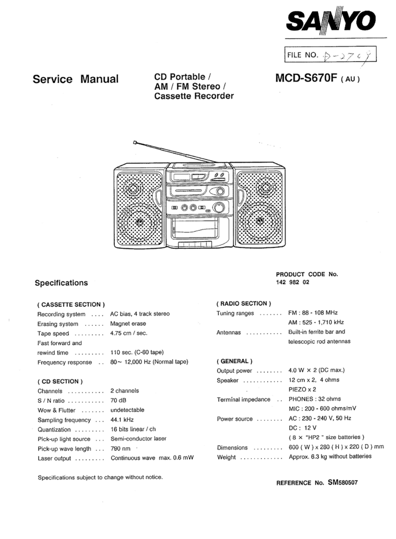
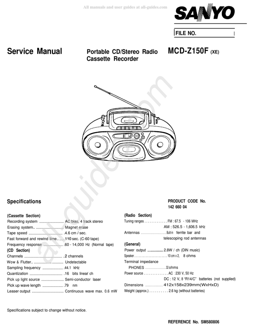
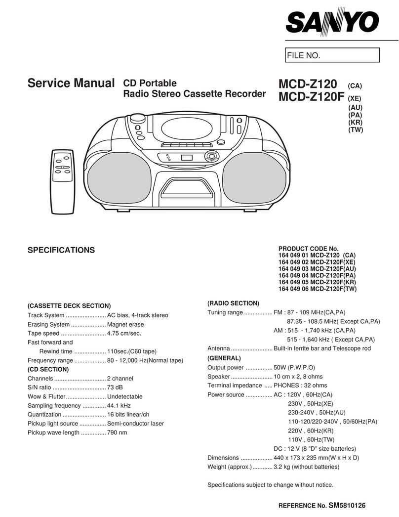
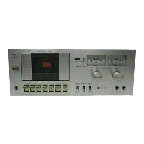
Sanyo M4440 User manual

SERVICE
MANUAL
MINI
CASSETTE
STEREO
_—
M4440
142
33801
SPECIFICATIONS
Power
Source
7
Fast
Forward
Time
.............
150sec.
(C-60
cassette)
DEA
Aad
6V
(UM-3,
HP
7,
AA
Cell,
Mignonzellen,
R6}x
4
Rewind
Time.................
150sec.
(C-60
cassette)
Output
Power
................
30
mW
(maximum)
Frequency
Response
............
63
—
10kHz
Current
Consumption
(at
VR
min)
Signal
to
Noise
Ratio...
..........
45dB
Playback
mode...............
110mV
Crosstalk
(with
Fe203}
Fast
Forward
mode............
140mV
Track
to
Track...
2.
...00200..
55dB
Rewind
mode
...............
140mV
Channel
Separation.
.......20:...
33dB
WapeSpeed?:
&
oc
2
y's
ek
Wet
aae
ales
1-7/8ips.
+3%
Hum
&
Noise...
2...
ee
eee
43dBs
(Vol
max.)
Wow
&
Flutter...
2.0.0...
ee
0.35%
(WRMS)
Specifications
subject
to
change
without
notice.—
WM-5957
Seo

MECHANICAL
ADJUSTMENTS
GENERAL
REMARK
Before
adjusting
the
mechanism
of
this
unit,
wipe
the
tape
contacting
surfaces
clean
as
well
as
the
contacting
surfaces
of
the
driving
parts
with
a
soft
cloth
soaked
in
alcohol.
Trouble
may
occur
because
of
oil
and
grease
stains.
FLYWHEEL
THRUST
ADJUSTMENT
The
clearance
between
the
Flywheel
Thrust
and
the
Flywheel
should
be
0.1
—O.2mm
with
the
Chassis
upside
down.
If
necessary,
adjust
the
clearance
with
the
following
procedure.
1.
While
moving
the
Capstan
up
and
down,
slowly
turn
the
Flywnee!
Thrust
clockwise
to
obtain
the
clearance
of
‘’0”
(zero)
between
the
Flywheel
Thrust
and
Flywheel.
Adjustment
Flywheel
Support
=
—
Flywheel
Thrust
0.1
—
0.2mm
¢
Capstan
Flywheel
NOTE:
Do
not
turn
the
Flywheel
Thrust
forcibly.
2.
Turn
the
Flywheel
Thrust
counterclockwise
by
approxi-
mately
45°
from
the
zero
clearance
position.
3.
After
the
adjustment,
secure
the
Flywheel
Thrust
with
paint
or
glue.
POWER
SWITCH
POSITION
ADJUSTMENT
1.
Press
the
play
button.
2.
While
slowly
pushing
the
F.F.
button,
check
to
see
that
the
Power
Switch
once
opens,
then
closes
after
the
F.F.
Gear
and
Take-up
Gear
engaged.
3.
If
necessary,
loosen
the
screw
fastening
the
Power
Switch
and
adjust
the
switch
position
by
moving
the
Power
Switch
as
illustrated.
Power
Switch
Take-up
Gear
4.
After
the
adjustment,
tic’
1
the
screw
and
secure
the
screw
with
paint
or
glue.

ELECTRICAL
ADJUSTMENTS
EQUIPMENT
REQUIRED
@
VTVM
@
Frequency
Counter
@
Dummy
Load
(34
ohm)
@
Test
Tapes
*
3kHz
Test
Tape
for
the
Tape
Speed
Adjustment
*
10kHz
Test
Tape
for
the
Head
Azimuth
Adjustment
@
Alignment
Too!
NOTE:
Before
the
Electrical
Adjustments,
set
the
unit
as
follows:
©
Talk:
SWITGRY
cs.
45
5.452
Ge
ve
apa
tie
eae
ae
aes
OFF
®
“TOME:
SWIC:
ed
Selva
Reeser
Tanna
a
ee
oe
ae
Be
a
High
*
Balance
Control..............-
O
(Center
Position)
*
Pitch
Control
............0.-
0
(Detent
Position)
*
Supply
a
regulated
DC
6V
power
to
the
DC
6V
Jack
(J2).
TAPE
SPEED
ADJUSTMENT
1.
Remove
the
Battery
Compartment
Batteries
from
the
compartment.
Lid
and
take
out
2.
Connect
a
frequency
counter
to
the
Headphone
Jack
(J1)
as
illustrated
and
insert
a
3kHz
test
tape
into
the
cassette
compartment.
34
ohm
=
Dummy
Load
7
Frequency
Counter
3
kHz
(43%)
l
HEAD
@
pyones
3.
While
playing
back
the
test
tape,
adjust
the
tape
speed
by
turning
the
potentiometer
(P301)
on
the
P.C.Board
with
an
alignment
too!
until
the
frequency
counter
reads
3kHz.
Adjustment
R/P
HEAD
AZIMUTH
ADJUSTMENT
1.
Remove
the
cassette
compartment
lid
by
following
the
instructions
for
it.
2.
Connect
a
VIVM
to
the
Headphones
Jack
as
illustrated
and
play
back
a
10kHz
test
tape.
34
ohm
Dummy
Load
yi,
VTVM
(Max.}
@
pee
PHONES
Adjustment
Play
Back
Head
Adjusting
Screw
NO.1
position
LEFT
Channel
NO.3
position
Adjustment
NO.2
position
RIGHT
Channel
3.
Turn
the
azimuth
adjusting
screw
until
the
Left
channel
on
the
VTVM
becomes
maximum.
(No.
1
position)
4,
Reconnect
the
VTVM
to
the
Right
channel.
5,
Then,
turn
the
azimuth
adjusting
screw
again
until
the
Right
channe!
output
on
the
VTVM
becomes
maximum.
(No.
2
position)
6.
Turn
the
adjusting
screw
to
the
center
of
the
No.1
and
No.
2
positions
as
illustrated.
(No.
3
position)
7.
Repeat
the
above
described
adjustment
several
times.
8.
After
the
adjustment,
secure
the
adjusting
screw
with
paint
or
glue.

Part
No.
PACKAGE
PARTS
LIST
Description
Description
AMPLIFIER
P.C.B.
ASSY
141
6
1419
53100
141
6
1419
53200
141
6
1449
70800
141
6
2519
12090
141
6
2519
15026
141
6
3919
39000
141
6
4559
00100
Case
Top
Case
Bottom
Styrofoam
Case
Poly
Cover
Poly
Cover
Plain
Pad
Seria!
No.
Sheet
ACCESSORIES
4
1529
70200
4
2419
73972
141
2
1769
05100
141
2
1819
12000
141
2
1829
04000
141
6
4419
18100
142
6
4119
12200
Headphone
Cassette
Shoulder
Strap
Carrying
Case
Cassette
Pouch
Caution
Tag
Instruction
Book
CABINET
4
1539
70620
0
1119
68406
0
1119
74700
0
1339
09302
2
1119
64902
2
1119
69600
2
1419
12800
2
1519
27500
141
2
1619
77000
141
2
2149
15300
141
2
2529
03100
141
2
3899
10100
141
2
4219
04001
141
2
4469
34600
141
2
4469
36500
141
2
7529
90200
101
3
1302
00411
103
3
1302
00511
127
3
1317
03018
202
5
8220
14120
141
2
1619
76900
141
2
2449
37000
141
2
3229
31900
141
2
4729
00100
101
31302
00611
131
3
1302
00411
CC1
0
2500
KEOOC
141
2
4469
31800
141
141
141
141
141
141
141
Microphone
Completed
Cabinet
Top
Cabinet
Bottom
Assy
Battery
Lid
Assy
Cabinet
Front
Cabinet
Jack
Rating
Plate
Microphone
Grille
Pause
Button
Cabinet
Bracket
Shaft
Microphone
Holder
Screw
M2.0x6
Cushion
Cushion
Bottom
Post
Screw,
Pan
Hd.
+M2.0x4
Screw,
Pan
Hd.
Tapping-2
+M2.0x5
PC
Screw,
Pan
Hd.-1
+M1.7x3.0
Diode,
SLP141B
(Operation)
Microphone
Sensor
Button
Sheet
Shield
Plate
Lug
Screw,
Pan
Hd.
+M2.0x6
Screw,
Pan
Hd.
C
SW
+M2.0x4
Ceramic
0.001
uF
50V
+10%
Damper
AMPLIFIER
P.C.B.
ASSY
BSH
hes
WH
am
Ba
pYNAINA
4
1329
76510
2
1639
40300
2
4219
23500
2
1639
37401
2
4219
08900
2
1639
37501
2
4219
08900
101
3
1302
00311
141
2
4179
04400
141
2
4729
04700
141
2
4729
05000
4
2359
75260
4
2359
72954
4
2319
74420
42319
74410
CC8
2
1500
KEOOC
CD10
5500
0002V
CD4
7
663A
0002V
CM3
3
3500
KOOMV
CD10
6160
0002V
CM6
8
3500
KOOMV
CD4
7
5250
0002V
141
141
141
141
141
141
|
Amplifier
P.C.B.
Assy
Control
Knob
Screw
Control
Knob
Screw
Speed
Control
Knob
Screw
Screw,
Pan
Hd.
Plate
Nut
Staple
10
Staple
5
Jack
1P
(Headphones)
Ext.
Power
Socket
Slide
Switch
(Tone)
Slide
Switch
(Talk)
Ceramic
820
pF
Electrolytic
1
uF
Electrolytic
47
wF
Mylar
0.033
uF
Electrolytic
10
pF
Mylar
0.068
nF
Electrolytic
4.7
uF
+M2.0x3
50V
+10%
25V
Sa
CC
(gE
GY
CC1
0
2500
KEOOC
CC1
0
2500
KEOOC
CD2
2
663A
0002V
CM6
8
3500
KOOMV
CM1
0
3500
KOOMV
CD10
763A
0002V
CD2
2
7100
0001V
CD3
3
7100
0001V
CCS
6
1500
KEOOC
CC8
2
1500
KEOOC
CD1
0
5500
0002V
CD4
7
663A
0002V
CM3
3
3500
KOOMV
CD1
0
6160
0002V
CM6
8
3500
KOOMV
CD4
7
5250
0002V
CC1
0
2500
KEOOC
CC1
0
2500
KEO00C
COD2
2
663A
0002V
CM6
8
3500
KOOMV
CM1
0
3500
KOOMV
CD1
0
763A
0002V
CD2
2
7100
0001V
CD3
3
7100
0001V
CC5
6
1500
KEOOC
CD2
27100
0001V
CC1
0
2500
KEOOC
CD10
7100
0001V
CA2
2
4100
MOOOV
CM3
9
2500
KOOMV
CM1
0
3500
KOOMV
CD10
7100
0001V
CD2
2
7100
0001V
CD47
7100
0001V
CD4
7
7100
0001V
202
5
9530
44810
206
5 1084
14010
206
5
1084
14010
206
5
0793
16020
4
2539
70850
4
2539
70840
4
2229
72640
203
5
5000
53650
203
5
5000
53650
203
5
6980
59860
203
5
5210
53660
203
5
5210
53660
203
5
4830
60860
203
5
5210
53660
203
5
5210
53660
203
5
4830
60860
RP4
7
3121
JTOOO
RP1
0
3121
JTOOO
RP1
0
1121
JTOOO
RP3
6
2121
JTOOO
RP1
0
4121
JTOOO
RP1
23121
JTOOO
RP1
2 2121
JTOOO
RP2
2
1121
JTOOO
RP1
00121
JTOOO
RP1
0
2121
JTOOO
RP1
0
3121
JTOOO
RP1
20121
JTOOO
RP4
7
3121
JTOOO
RP1
0
3121
JTOOO
RP10
1121
JTOOO
RP3
6
2121
JTOOO
RP1
0
4121
JTOOO
RP1
2 3121
JTOO0O
RP1
2
2121
JTOOO
Ceramic
Ceramic
Electrolytic
My
lar
Myl!ar
Electrolytic
Electrolytic
Electrolytic
Ceramic
Ceramic
Electrolytic
Electrolytic
Mylar
Electrolytic
Mylar
Electrolytic
Ceramic
Ceramic
ectrolytic
yiar
ylar
ectrolytic
Electrolytic
ectrolytic
0.001
pF
0.001
uF
22
uF
0.068
uF
0.01
uF
100
uF
220
uF
330
uF
560
pF
820
pF
Tur
47
uF
0.033
uF
10
uF
0.068
pF
4.7
uF
0.001
pF
0.001
uF
22
uF
0.068
uF
0.01
uF
100
pF
220
uF
330
BF
560
pF
220
pF
0.001
uF
100
pF
0.22
pF
0.0039
uF
0.01
uF
100
pF
220
pF
470
uF
470
pF
E
M
M
E
ytic
Ceramic
Electrolytic
Aluminum
Mylar
Mytar
Electrolytic
Electrolytic
Electrolytic
ectrolytic
Diode,
DS448
IC,
LA4140
IC,
LA4140
IC,
LA3160T
Choke
Coil
(200
uH)
Choke
Coil
(220
pH)
Potentiometer
(B-350)
Transistor,
25C536
Transistor,
2SC536
Transistor,
2SB598
Transistor,
2SC536
Transistor,
2SC536
Transistor,
2SA608
Transistor,
2SC536
Transistor,
2SC536
Transistor,
2SA608
Pretty
47k
ohm
Pretty
10k
ohm
Pretty
100
ohm
Pretty
3.6k
ohm
Pretty
100k
ohm
Pretty
12k
ohm
Pretty
1.2k
ohm
Pretty
220
ohm
Pretty
10
ohm
Pretty
1k
ohm
Pretty
10k
ohm
Pretty
12
0hm
Pretty
47k
ohm
Pretty
10k
ohm
Pretty
100
ohm
Pretty
3.6k
ohm
Pretty
100k
ohm
Pretty
12k
ohm
Pretty
1.2k
ohm

Part
No.
RP2
2
1121
RP10
0121
RP1
0
2121
RP10
3121
RP1
20121
RP1
2
2121
RP6
8
1121
RP8
2
212i
RP8
2
2121
RP3
3
4121
RP1
0
3121
RD3
0
A251
RD3
3
0251
RP1
0
3121
RP2
2
2121
RP43
1121
RP30
1121
RP2
2
3121
RP3
3
2121
RP15
1121
RP10
4121
RP1
2 3121
RP3
3
2121
RP4
7
2121
JTOOO
RP3
3
2121
JTOOO
RP3
9
1121
JTOOO
RP8
2
0121
JTOOO
RP1
2
1121
JTOOO
204
5
9000
01000
4
2229
73400
4
2229
71912
4
2229
73223
PARTS
LIST
(Continued)
Description
MECHANISM
Description
220
ohm
10
ohm
1k
ohm
10k
ohm
12
0hm
1.2k
ohm
680
ohm
8.2k
ohm
8.2k
ohm
330k
ohm
10k
ohm
3
ohm
33
ohm
10k
ohm
2.2k
ohm
430
ohm
300
ohm
22k
ohm
3.3k
ohm
150
ohm
100k
ohm
12k
ohm
3.3k
ohm
4.7k
ohm
3.3k
ohm
390
ohm
Pretty
82
ohm
Pretty
120
ohm
Thermister,
SDT100
Volume
Control
(Volume,
A-20k)
Volume
Control
(Balance,
B-20k)
Volume
Control
(Pitch,
B-8k)
+5%
+5%
+5%
+5%
+5%
+5%
+5%
45%
+5%
+5%
+5%
+5%
+5%
+5%
+5%
+5%
+5%
+5%
+5%
+5%
+5%
+5%
+5%
+5%
+5%
+5%
+5%
£5%
1/8W
1/8W
1/8W
1/8W
1/8W
1/8W
1/8W
1/8W
1/8W
1/8W
1/8W
1/4W
1/4W
1/8W
1/8W
1/8W
1/8W
1/8W
1/8W
1/8W
1/8W
1/8W
1/8W
1/8W
1/8W
1/8W
1/8W
1/8W
Pretty
Pretty
Pretty
Pretty
Pretty
Pretty
Pretty
Pretty
Pretty
Pretty
Pretty
Carbon
Carbon
Pretty
Pretty
Pretty
Pretty
Pretty
Pretty
Pretty
Pretty
Pretty
Pretty
Pretty
Pretty
Pretty
MECHANISM
4
2319
71860
42319
74750
4
2429
71210
4
5279
70904
0
3119
16103
0
3789
01300
105219.
08100
1
0
5369
00701
1
0.5369
01100
0
5419.01000
1
0
5519
06200
107319
17301
107419
19706
07419
19806
0
7419
19906
141
07419
20106
141
0
7419
20200
141
0
7419
20300
141
0
7439
05600
141
0
7439
05701
141
0
7439
05800
141
141
22449
37100
141
2
2449
37600
141
2.3159
02400
141
23529
18101
141
2
4179
01800
141
2
4219
03000
141
2
4219
04000
141
2
4219
09000
141
2
4219
11400
141
2
4459
15900
141
2
4469
00500
141
2
4469
17200
141
2
4539
06900
141
2
4539
08000
Leaf
Switch
(Power)
Leaf
Switch
(Muting)
Play
Head
Motor
Chassis
Assy
Motor
Bracket
Assy
Flywheet
Assy
Reel
Plate
Assy
Completed
Ree!
Plate
Pinch
Roller
Assy
Take-up
Idler
Assy
Slide
Base
Assy
F.F.
Lever
Assy
Rewind
Lever
Assy
Play
Lever
Assy
Stop
Lever
Assy
Lock
Plate
Assy
Select
Crank
Assy
Eject
Lever
Assy
Record
Lock
Lever
Assy
Take-up
Pulley
Arm
Assy
ensor
Lever
Assy
Sheet
Sheet
Handle
Bracket
Spacer,
Head
Nut
Screw
M2.0x3
Screw
M2.0x6
Screw
M2.0x2
Screw
M2.0x5.5
Motor
Cushion
Flywheel
Thrust
Cushion
Washer
Washer
a
eh ed
ND
eID
Sn
ed
a
a
ee
a
es
eli
as
ee
es
141
2
4539
09300
141
2
4539
24600
41
2
4619
00901
141
2
4729
04000
141
2
4729
07000
141
2
5519
23300
141
2
5519
31500
141
2
5649
10800
141
2
5649
10900
141
2
5649
12800
141
25719
07700
141
2
5719
07800
141
2
5729
14100
141
2
7149
02700
141
2
7419
52300
141
27419
52600
141
2
7439
13300
141
2
7539
01700
141
2
8119
06000
141
2
8139
04100
141
2
8219
17800
141
2
8219
24800
141
2
8459
02601
141
2
8519
12200
141
2
8519
33000
141
2
8519
43000
141
2
8519
47400
141
2
8519
50701
141
2
8519
57300
141
2
8519
63600
141
2
8519
74700
141
2
8519
75100
141
2
8519
75700
141
2
8519
77000
141
2
8539
31500
141
2
8549
06000
101
3
1302
00411
101
3
2502
00811
110
3
1102
00023
110
3
3202
00082
112
3
1301
50082
112
3
1302
00082
131
3
1302
00411
141
2
4469
17200
NOTES:
1.
141
2
5719
09000
Washer
Washer
Brake
Tube
Lug
Lug
F.F,
Gear
Drive
Idler
Take-up
Belt
Drive
Beit
Counter
Belt
Spacer
Spacer
Spacer’
Capstan
Metal
Brake
Plate
Shut-off
Lever
Select
Lever
Review
Lever
Post
Counter
Counter
Bracket
Spacer,
Pinch
Roller
Tape
Guide
Flywheel
Plate
Spring,
Motor
Lack
Spring,
Index
Lock
Lever
Spring,
Locker
Spring,
Head
Spring,
Play
Lever
Spring,
Stop
Lever
Spring,
Brake
Spring,
Brake
Spring,
Record
Lock
Spring,
Pinch
Roller
Spring,
Lock
Plate
Spring,
Cassette
Spring,
Slide
Base
Screw,
Pan
Hd.
Screw,
Cylinder
Hd.
Smaii
Round
Washer
Tooth
Outer
Washer-B
E
Ring
E
Ring
Screw,
Pan
Hd.
C
SW
Cushion
+M2.0x4
-M2.0x8
M2.0
M2.0
M1.5
M2.0
+M2.0x4
and
Description.
2.
Ordering
quantity
of
screws
and
resistors
must
be
multiple
of
10
pes.
a
feds
a
Se
et
sy
aS,
ee
ee
se
et
a
=
PBPNWN-HPHNHH
HK
KH
Parts
order
must
contain
Model
Number,
Part
Number

EXPLODED
VIEW
(Cabinet)
i
[41
2
2529
03100
147
21119
69600
Cabinet
Jack
emxraracite
|
14101119
69406
Caninet
Tos
Comp)
202
5
8220
14120
SLP
1418
141
23899
10100
Holder
Mike
{
«
T!
3
0
BN
—_
Waa?
Se
Re
A
:
f
141
21519
27500
Grille
Mike
141
2
4469
36500
Cushion
141
2
4469
34600
'|
Cushion
141
22149
15300
Poa
Bracket
Cabinet
141
21619
77000
Button
Pause
14121119
64902
Cabinet
Front
141
2
7529
90200
ng
9
+PMS
M2.0x4
Post
Bottom
ie
141
2
7529
90200
Post
Bottom
101
3
130200411
#PMS
M2.0x4
741
2
1619
76900
Button
Mike
Sensor
Bk
131
31302
00411
+PMS
C
SWM2.0x4
141
2
2449
37000
rasa
Sheet
2
131
2
1302
00411
@*~
+PMS
C
SW
M2.0x4
141
23229
31900
Plate
Shield
141
22449
37000
41
22443
370
1
.
SS
Sheet
Sheet
131
3
1302
00411
+PMS
C
SWM2.0x4
|
141
2.4729
00100
oF
Lug
1410
1119
74700
101
31302
00611
Cabinet
Bottom
Assy
+PMS
M2.0x6
14124219
04001
M2,
=
127
3
1317
03018
Screw
M2.0x6
PC
+PMS-1
M1.7x3.0
141
24219
04001
Screw
M2.0x6
z
14124219
04001
—~@
Screw
M2.0x6
141
24219
04001
Screw
M2.0x6
14121419
12801
Rating
Plate
141
0
1339
09302
Lid
Battery
Assy
2G
/?

(Chassis
Top)
EXPLODED
VIEW
(continuea)
147
24279
03000
Screw
¥2.0x2
_
»
147
0
7439
05600
Lever
Eyect
Assy
1417
24219
O300e
ao
¢
%
=
S
NS
°
ad
141
2
8539
31500
Spring
Cassette
141
25719
07800
Spacer
—®
141
28519
43000
fh
Spg
Lacker
ye
141
27419
52600
—.
=
Lever
Sefect
1013
2502
00811
_
“
1073
1302
00411
CMS
M2.0x8
‘Se
oMe
Mobs
2
¢
082
+
eB
eB
141.2.4729
04000
Ge
ts
4
2429
71810
:
Play
Head
1103
1102
00023
;
SRW
M20
;
141
2.4219
09000
ob
141
2.4219
03000
,
Screw
M2.0x2
>
141
23529
18101
Screw
M2,0x3
E
ye
Spacer
Head
a
141
2.8219
24800
14128519
47400
?
Guide
Tape
Spring
Head
141
25719
09000
141
24219
03000
&
Spacer
|
Y
Screw
M2.0x3
141
25719
07700
eo
Spacer
1410
7419
20300
Crank
Select
Assy
nt
141
0
7439
06000
{
Lever
Sensor
Assy
141
2.8119
06000
Counter
141
25649
12800
Belt
Counter
141
07319
17301
dase.
Side
ASY.
141
28519
75700
Spring
Pinch
Rolle.
oe
141
24219
03000
ering
Pi
r
Screw
M2.0x3
1723
1301
50082
|
E
RingM1.5
eg
i
141
28139
04100
Bracket
Counter
141
28549
06000
Spring
Base
Slide
Assy
Pinch
Roller
141
0
5419
01000
|
|
1
141
26219
17800
Spacer
Pinch
Rolier
147
03119
16103
Chassis
Assy
ID
yi
2
2449
37100
wt
i
eer
dy
112.3
1302
00082
112
3
1302
00082
E
Ring
M2.0
E
Ring
M2.0
|
\
i
4
-$
141
0
5369
01100
141
0
5369
00701
Reel
Plate
Comp/
Rell
Plate
Assy

EXPLODED
VIEW
(continue)
(Chassis
Bottom)
wr
Ring
141
2
8519
63600
Spring
Brake
Sa?
141
2851950701
P
Spring
Lever
Play
spo"
1123
1301
50082
a
E
RingM15
1123
1301
50082
«
E
Ring
MI
)~
yr
14107419
19706
Lever
F.F.
Assy
=
oA
141
28519
33000
Spg
Lever
Lock
Index
1123
1301
50082
ERingMi.s
14107419
19806
1472
palg,
23300
Lever
Rewind
Assy
Gear
F
1123
1301
50082
S
E
Ring
M15
141
2.4619
00901
1123
1301
50082
os:
112.3
1301
50082
Tube
Brake
“€
hae
E
Ring
M1.5
E
Ring
41.5
y
1
%
Cry
tt,
141
27149
02700
|
Plate
Brake
1410
7419
20200
i
Plate
Lock
Assy
A
1123
130
sat
50082
—@
141
28519
74700
Lf
Spring
Brake
1123
13a!
50082
141
2
7439
13300
Lever
Review
1013
130200411
ag
PMS
M2.0x4
4
2319
71860
Switch
Leat
141
2851950701
Pa
Spring
Lever
Play
4
as
14107419
19906
Lever
Play
Assy
112.3
1302
00082
ey
E
Ring
M2.0
aa
op
141
2.8519
12200
Spg
Motor
Lock
:
141
28519
77000
|
Spring
Plate
Lock
141
07419
20106
Lever
Stop
Assy
141
28519
75100
i
1123
fot
es
E
RingM
Spring
Rec
Lock
|
E
RingM
141
28519
57300
we
oe
or
[47
2
4539
08000
Spg
Lever
Stop.
[slg
s5e
31500
@~
washer
vi
141
0
7439
05701
Lever
Lock
Rec
Assy
141
27419
52300
Lever
Shut-off
141
2
4469
00500
Thruse
Flywheel
14124219
11400
Screw
M2.0x5.5
ig
CA.
141
2.4469
17200
Cushion
141
24219
04000
Screw
M2.0x6
~s
4
141
28459
02601
Plate
Flywheel
141
2
4459
15900
Cushion
Motor
141
27539
01700
Post
141
0
3789
01300
Bracket
Motor
Assy
141
0.5219
08100
1312
130200411
Pinwneeh
A5%:
+PMS
C
SWM2.0x4
141
2
5649
10900
Belt
Drive
4
5279
70904
141
2417901800
Motor
Nut
141
2
4469
17200
Cushion
141
25729
14100
Metal
Capstan
141
2
4539
06900
Washer
141
2
2449
37600
Sheet
—3—
141
2.5649
10800
Belt
Take-up
141
2.4539
24600
i
Washer
wr
b'R?
1301
50082
@*—
E
Ring
M15
|
141
0
7439
05800
Arm
Pul
Take-up
Assy
141
24219
04000
of
Screw
M2.0x6
141
25719
07800
Spacer
141
0
5519
06200
‘dler
Take-up
Assy
147
28519
63600
ye
Spring
Brake
Ey
141
24219
03000
Ss
Screw
M2,0x3
4
2319
74750
oh
tat
Switch
141
24219
03000
Screw
M2.0x3
UAC
141
2
4729
07000
Lug
141
23159
02400
|
la
|
Bracket
Handle

wal
.
co
sate
tenner
Jl
HEADPHONES
JACK
VRI
VOLUME
CONTROL
VR2
BALANCE
CONTROL
S4
TALK
SWITCH
ON
OFF
re
fal
S3
TONE
SWITCH
HIGH==
LOW
PARTS
LOCATION
J2
EXT,
POWER
JACK
VR3
PITCH
CONTROL
FQ—

WIRING
DIAGRAM
J2
BATTERY
EXT.
POWER
JACK
RED
.
RED
AA”
Cell
X
4
|
.
6YV
<a
:
7
mn
=
.
ate
an
x
7
i
GREEN
pe
a
‘SI
.
POWER
SWITCH
-
C
Lo
a
JI
AF
=
HEADPHONES
Pi]
JACK
ORANGE
ve
ORANGE
VRI
VOLUME
CONTROL
BLUE
—s
2
nme
lg
ie
MIKE
|
MUTE
SWITCH
VR2
BALANCE
CONTROL
HDI
PLAY
HEAD
¥
a
Ss
okey
WHITE
|e
“GRAY
i
ae
TONE
SWITCH
LOW—*+=
HIGH
PITCH
OPEARATION
BLUE
BLUE
CONTROL
INDICATOR
;
—11—
| :
9.

SCHEMATIC
DIAGRAM
ic30i
LASIGOT
aiore201
2SC536
icior,ic2zo1
LA4I40
PRE-
AMPLIFIER
TONE
SWITCHING
CIRCUIT
POWER
AMPLIFIER
teh
R320
BUILT
-
IN
MIKE
oy
ied
aay
5.7BV
6.0V
WA
——\W——
—\y—————~
C305
+]
c307
R321
+]
c308
R322
tpC309
+0310
0,0039y
—|
!O00yp
390
~f
220p
82
~f470p
—f
470
Lhe
2S
+
10V
1
10V
Lisgv
1
ev
$2
MUTING
poh
SWITCH
$3
clo
RIO
R12
Jt
TONE
(2
HEADPHONES
JACK
oY
Vv,
HDI-!
PLAYBACK
HEAD
22p
6,3V
LOWLo
o
HIGH
clog
or
_
ce
cil2
3301001
5.67V
IOV
arias
C106
0068p
1Opt6Vv
220
WA
Be
RIOF
VRI-I
12k
7.
.
A-20K
VOLUME
CONTROL
C205
JOpI6V
HDI-2
ae
PLAYBACK
HEAD
t
~
+
1.3V
=
Se
a
t
C202
|
7
!
C201
pia
ahha
=
=820P
a307
2SA608
INDICATOR
CIRCUIT
No.
Name
Position
S11
Power
Switch
OFF
S2_
|
Muting
Switch
OFF
S32
|
Tone
Switch
HIGH
S4_
|
Talk
Switch
OFF
VRI-2
sae
|
=
SBOaH
CHOKE
oop
S|
2
5
JH
POWER
Pees
SON.
L73V
5.9V
PH
nets
Cane
7
2304
Q30!
*To3
CHOKE
re
ta
DS448
-¥#320p
anor
OV
FLYWHEEL
+
O30
:
Liov
EXT.
POWER
JACK
DIODE
+
"AA
Cell
x4
Ty
e
6V
LL
0302
R318
SLP-I41B
—
j.2y|
Q305
-
3.3K
OPEARATION
me
°
L
L
1
INDICATOR
Q306
Q306
,Q305
2$C536
aQ304
2SAGOB
Q303,9302
2$C536
930:2SB598
MOTOR
GOVERNOR
CIRCUIT
+B-8K
PITCH
CONTROL
a
(

IC
&
TRANSISTOR
LEAD
IDENTIFICATION
FRONT
VIEW
BOTTOM
VIEW
|
TRANSISTOR
FRONT
VIEW
(Oe
2S8C536
LA4140
oe
ae
ee
BOTTOM
VIEW
2SC536
FRONT
VIEW
2SA608
2SB598
fo
oo
o-}
B=
BASE
Bade
ets
C=
COLLECTOR
E>
EMITTER
BOTTOM
VIEW
LA3160T
BLOCK
DIAGRAM
Pre-Amp.
IN
NF
OUT
Vec
GND
OUT
NF
iN
Negative
Negative
Feedback
Feedback
—15—

SANYO
ELECTRIC
TRADING
CO.,
LTD.
OSAKA,
JAPAN
March/'81/7,000
Printed
in
Japan
Table of contents
Other Sanyo Cassette Player manuals

Sanyo
Sanyo M9998 User manual

Sanyo
Sanyo MCD-Z165F User manual

Sanyo
Sanyo MCD-Z12F User manual

Sanyo
Sanyo M9994K User manual

Sanyo
Sanyo MCD-ZX570M User manual

Sanyo
Sanyo TRC-2050C User manual

Sanyo
Sanyo MCD-Z260F User manual

Sanyo
Sanyo MCD-Z330F User manual

Sanyo
Sanyo MCD-s900F User manual

Sanyo
Sanyo MCD-Z150F User manual
Sanyo
Sanyo MCD-S730F User manual

Sanyo
Sanyo MCD-Z530F User manual

Sanyo
Sanyo MCD-Z110F User manual

Sanyo
Sanyo MCD-Z165F User manual

Sanyo
Sanyo MCD-Z90F User manual

Sanyo
Sanyo M9998K User manual

Sanyo
Sanyo MCD-Z8F (AU) User manual

Sanyo
Sanyo M7790K User manual

Sanyo
Sanyo MCD-UB575M User manual

Sanyo
Sanyo MCD-S670F User manual