manuals.online logo
Brands
  1. Home
  2. •
  3. Brands
  4. •
  5. Sanyo
  6. •
  7. Projector
  8. •
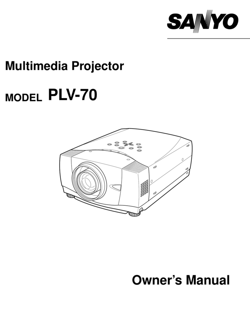
  9. Sanyo PLC-8800E User manual

Sanyo PLC-8800E User manual

SERVICE
MANUAL
Mu!t!-m.d!a
Projector
F/^F
NO.
Mode)
no.
PLC-8800E
(Europe,Asta,Africa,M.E.)
Content
Specifications
Disassemblies
and
Replacement
Procedures
Safety
Instructions
Alignment
Procedures
Semiconductor
&
1C
Block
Diagrams
Parts
-List
Take
notice
of
"SCHEMATIC
DIAGRAMS'
Description
of
Projector
Wave
forms
Block
Diagrams
CPU
Input/Output
Port
Functions
Component
and
Test
Point
Locations
Schematic
diagrams
OR!G)NAL
VERSION
Service
Ref.No.
PLC-8800E-00
PRODUCT
CODE
P6KA
(PLC-8800E-00)
;
1122
036
00
REFERENCE
NO.
SM525045
Contents
Specifications
Contents
Specifications
-
Disassemblies
and
Repfacoment
Procedures
Mechanical
Disassembles
...------....-
Opticai
Unit
Disassemblies
---...........
LCD
Panei
Repiacement................
Assy
Lamp
Replacement
-.--....-......
Safety
instructions
........................
Alignment
Procedures
------
Eioctricai
Adjustments
" "
iiC
Data
Adjustments
"
"
-
Focus
Adjustments
------
Convergence
Adjustments
Semiconductor
&
)C
Block
Diagrams
iC
internai
Biock
Diagrams
"
"
iC-Tr
Package
Outfine
Drawings
-
-
3
-
3
-
9
10
11
12
14
14
19
22
24
26
26
36
Parts
-List
................
Etectricai
Parts
List
" "
-
Cabinet
Parts
List
-.-----
Opticai
Parts
List
-.---.-
LCD
Panei
Unit
Parts
List
Take
notice
of
"SCHEMATIC
DIAGRAMS"
Description
of
Projector
.................
Wave
forms............................
Btock
Diagrams
........................
CPU
input/Output
Port
Functions-..-----..
Component
and
Test
Point
Locations
Schematic
diagrams
.............
37
37
60
62
64
65
66
72
76
77
81
93
Specifications
Projector
Type
Otmen$)on<
(W
x
H
x
D}
Mat
Weight
LCD
Pane!
System
Mumber
ot
Ptxeta
Cotor
Syetem
SMnn)ne
FMquMoy
Projection
image
S!ze
(Dtagonat)
Contract
Ratto
Hor!zontat
ReM)utton
ProJecHon
t^M
Throw
Diatanoe
Pr&jecHoa
Ltmp
ProJMHon
Mttrof
AV
)nput
tectf*
Computer
tnput
JMh
Mon!tor
Output
Jack
ComputM-
Audfo
(nput
J<ett
V)deo
Momtor
Output
Jack
Audto
MonttOf
Output
Jack*
Other
Jac)t$
BuMt-fn
SpMtMr
tmage
E^vttfon
Ad}u<^ent
Vo)tage
Power
CofMumpdon
Operating
TemperatuFC
Storage
Temperature
Remote
Contro)
Battery
MuM-media
Proiector
10.2'
(260
mm
)
x
6.3'
(159
mm)
x
15.4'
(39]
mm)
13.0
)bs
(5.9
kg)
1.3'
TFT
Active
Matrtx
type
(Th^
F)!m
Trans!stor)
^
3
2.359.296
{786.432
(1.024
x
768)
^
3}
4
co)or
system
(PAL.
SECAM.
NTSC
and
NTSC4.43)
H-sync.
15-80
KHz.V-sync.50-100
Hz
Adjustabte
from
20'
to
400'
100:1
(ANSi)
800
TV
)ines
f2.5
-
3.2
tens
wtth
1.77'
-
2.95'
Motor
zoom
and
focus
3.6'(1-1
m)-47'(14.3m)
Metaf
Ha!!de.
120
watt
type
Dichroic
mirror
and
X-prism
system
PHONO
(RCA)
Type
x
1
(Video.
Audio
R
and
L)
and
D)N
4
pin
(S-V!deo)
x
1
(VGA)
HDB15
Tormina!
x2.
Muit!-po)e
12
pin
(Contro)
port)
x
2
(VGA)
HDB15
Tormina!
x
1
Mini
Stereo
Type
x
2
PHONO
(RCA)
Type
x
1
PHONO
(RCA)
Type
x
1
(R
and
L)
EXT.
Speaker
Jack
x
1
)NT.
SP-
Stereo
(R
and
L),
2
watt
RMS
(T.H.D.
10%)
UD[o6"
100
-
120V
AC.
50/60
Hz
or
200
-
240V
AC.
50/60
Hz
2.0A
(Max.
Ampere)
or
1.2A
(Max.
Ampere)
5t;-35t
-
10^-601
(2)
AA
Type
UM-3
RM-06
!'N
^
w
!
:J
A
t
'^assemblies
and
Renlacement
Procedures
Mechanical
Disassemblies
CabmetTop
Remova!
1.
Remove
1
rear
screws
and
4
side
screws
of
the
cabinet
top.
2.
Grip
the
two
sides,
pu)!
the
cabinet
top
upward
and
remove.
Main,
A
/
V
,Comb.
Fi!ter
and
LED
Board
Remova!
1.
Remove
9
screws
on
the
Main
Board.
2.
pu!)
the
Main
Board
upward
and
remove.
3.
put!
the
A/V
Board
Downward
and
remove.
4.
Remove
3
screws,
then
remove
the
A/V
Board.
5.
Remove
2
screws,
then
remove
the
Comb.
Fitter
Board.
6.
Remove
1
screws,
then
remove
the
LED
Board.
Hotder
Lamp
Ba)!ast
Board
Lamp
Socket
Ho!der
Lamp
Baiiast
Board
and
Fan
(FN902)'Remova!
1.
Remove
3
screws
on
the
Hotder
Lamp
BaHast
Board.
2.
Remove
2
screws
on
the
Lamp
Socket.
3.
pu!!
the
Ho)der
Lamp
Baf)ast
Board
upward
and
remove.
4.
pu!)
the
Fan
(FN902)
upward
and
remove.
Optical
Unit
Remova!
1.
Remove
6
screws
securing
the
Optica)
Unit
and
pu<!
upward
to
remove.
power
switch
unit
remova!
1.
Remove
5
screws,
then
remove
the
power
switch
unit.
Fan(FN901)
and
Ho!der
Speaker
Removat
1.
Remove
2
screws
on
the
Fan.
2-
puh
the
Fan
upward
and
remove.
3.
Remove
2
screws,
then
remove
the
Hotder
Speaker.
4.
Remove
the
another
side
Speaker
repeat
step
3.
Ho!der
power
Board
Remova!
1.
Remove
6
screws
securing
the
Holder
power
Board
and
pu!!
upward
to
remove.
Speaker
Remova!
1.
Remove
2
screws
,
then
remove
the
Speaker.
Power,
Sub
power
and
A&M
Drtve
Board
Remova!
1-
Remove
6
screws
securing
the
power
Board
and
put)
upward
to
remove.
2.
puf)
the
Sub
power
Board
upward
and
remove-
3.
put)
the
A&M
Drive
Board
upward
and
remove.
Sub
power
Board
A&M
Drive
Board
BaHast
Board
and
Fan
L^mp
BaHast
(FN903)
Remova)
1.
Remove
2
screws
on
the
Ho)der
Lamp
Batiast
Board.
3.
put!
the
Shiotd
Lamp
pwb
Top-M6KA
upward
and
remove.
1.
Remove
4
screws
on
the
Lamp
Ba!)ast
Board.
3.
pu)!
the
Lamp
Ba!tast
Board
upward
and
remove-
4-
pu)!
the
Fan
(FN903)
upward
and
remove.
Ho)der
Lamp
BaNast
Board
Shiefd
Lamp
pwb
Top-M6KA
Fan(FN903)
Ho)der
Lamp
pwb
-M6KA
Optical
Unit
Disassemblies
Optica!
base
top
remova!
Remove
9
screws,
then
remove
the
Optical
base
top.
/^
^Optica)
Unit)
(optica!
base
top")
base
Bottom
LCD
Panel
Replacement
LCD
Pane!
unit
remova!
1.
Rermove
4
screws,
securing
the
LCD
Pane)
unit.
2.
Pu!)
out
the
LCD
Pane!
unit.
Remova)
Screws
]
Remova)
Screws
Remova)
Screws
LCD
Pane)
Rep!acement
Rermove
3
screws,
then
remove
the
LCD
Pane)
and
rep)eace
it.
Note
When
you
replace
the
LCD
panei,
Focus
adjustment
and
Con-
vergence
adjustment
must
be
done.
^
Green
Panei
unit
Red
and
Blue
Panel
unit
10
Metal
Halidc
LampAss'y
Replacement
Warning
^^^^___^^^^
For
continued
safety,
rep)ace
with
a
tamp
assemb)y
of
the
same
type.
Rtn?R^M
ttH^^n
A))ow
the
projector
to
coo)
for
at
)east
45
minutes
before
you
open
the
tamp
cover.
The
tnside
of
the
projector
can
become
very
hot.
Do
not
drop
the
tamp
module
or
touch
the
g)ass
bu)b!
The
glass
can
shatter
and
cause
)n]ury.
To
prevent
operator
injury,
the
tamp
cover
ts
)ocked.
Untess
the
guard
is
in
the
unlocked
position,
the
iamp
cover
wH)
not
disconnect
even
if
the
screws
have
been
removed.
1.
Disconnect
the
AC
cord
from
the
projector.
2.
Remove
1
screws
and
disconnect
the
lamp
cover.
3.
Remove
2
screws
and
pu!!
out
the
iamp
assembly
by
gripping
the
handle.
4.
Replace
the
tamp
assembly.
5.
Tighten
3
screws
to
secure
the
iamp
cover
to
the
iamp
assembly.
6.
Connect
the
detachable
AC
cord
to
the
projector.
7.
Reset
the
iamp
repiacement
monitor
timer.
NOTE:
Do
not
reset
the
LAMP
REPLACEMENT
MONITOR
TIMER,
except
after
the
iamp
replacement.^
Recommendat'on
7-1.
Press
the
MENU
BUTTON
and
the
MAIN
MENU
DISPLAY
diatog
box
wiii
appear.
7-2.
Press
the
POINT
LEFT/RIGHT
BUTTON(s)
to
seiect
SETTING
and
press
the
SELECT
(REAR
CLICK)
BUTTON.
Another
dialog
box
SETTING
DISPLAY
wil!
appear.
7-3.
Press
the
POINT
DOWN
BUTTON
and
a
red
arrow
wii!
appear.
7-4.
Move
the
arrow
by
pressing
the
POiNT
UP/DOWN
BUTTON(s)
to
select
Lamp
age
and
then
press
the
SELECT
(REAR
CLICK)
BUTTON.
When
you
reset
the
iamp
replace
monitor.
"lamp
replace
monitor
reset?"
is
displayed
for
confirmation.
7-5.
Move
the
arrow
to
Yes
and
then
press
the
SELECT
(REAR
CUCK)
BUTTON,
"OK?"
is
displayed
for
confir-
mation.
Move
the
arrow
to
Yes
and
then
press
the
SELECT
(REAR
CLICK)
BUTTON,
the
!amp
replace
monitor
is
reset.
Should
the
air
filter
become
cfogged
with
dust
particles,
it
will
reduce
the
cooling
fan's
effectiveness
and
may
result
in
internal
heat
build
up
and
short
tamp
life.
We
recommend
cleaning
the
air
fitter
after
the
projection
lamp
is
replaced.
Refer
to
AIR
FILTER
CARE
AND
CLEANING
on
the
Owner's
Manual.
How
to
check
the
tamp
i))umination
time
Service
Mode
1.
Checking
procedure
With
the
projector
in
operating
mode
(synchronize
picture
view
condition),
press
the
POINT
UP
button
for
20
seconds;
digital
display
wii)
appear
on
the
screen
for
5
seconds.
2.
Calculation
of
illumination
<
/'
illumination
Time
=1000--
Data
Value
)'
t
Note:
if
the
RESET
"YES"
!s
pressed,
the
data
of
illumination
time
wi!)
\
be
Initialized.
3.
Ca)cu!ation
example
1000-
987
=:13
Approx.
13
hour
of
illumination
11
F
/
Data
no.
Data
Service
tervtce
)——)
j
___)
Mode
!
37
!
J987J
Data
Va)ue
^
F
Su^-t'J
instructions
J
^
Safety
Instructions
^
Safety
Precauttons
WARN)NG:
The
chassis
of
this
projector
is
isolated
(COLD)
from
AC
tine
by
using
the
converter
transformer.
Primary
side
of
the
converter
transformer
and
)amp
power
suppfy
unit
circuit
is
connected
to
the
AC
iine
and
it
is
hot,
which
hot
circuit
is
identified
with
the
iine
in
the
schematic
diagram.
For
continued
product
safety
and
protection
of
personnel
injury,
servicing
should
be
made
with
qualified
personne).
The
following
precautions
must
be
observed:
1.
An
isolation
transformer
should
be
connected
in
the
power
iine
between
the
receiver
and
the
AC
iine
before
any
service
is
performed
on
the
projector.
2.
Compty
with
aii
caution
and
safety-
related
notes
provided
on
the
cabinet
back,
cabinet
bottom,
inside
the
cabinet
or
on
the
chassis.
3.
When
repiacing
a
chassis
in
the
cabinet,
always
be
certain
that
aii
the
protective
devices
are
installed
property,
such
as
control
knobs,
adjustment
covers
or
shields
and
barriers,
DO
NOT
OPERATE
TH!S
PROJECTOR
WITHOUT
THE
PROTECTIVE
SHIELD
iN
POSiTiON
AND
PRO-
PERLY
SECURED.
4.
Before
replacing
the
cabinet
cover,
thoroughly
inspect
the
inside
of
the
cabinet
to
see
that
no
stray
parts
or
toots
have
been
ieft
inside.
Before
returning
any
projector
to
the
customer,
the
service
personnel
must
perform
the
following
safety
checks
and
be
sure
that
it
is
completely
safe
to
operate
without
danger
of
efectricaf
shock.
Product
Safety
Notice
Product
safety
should
be
considered
when
a
compo-
nent
rep!acement
is
mada
in
any
area
of
the
projector.
Components
indicated
by
a
mark
(A
)
in
the
parts
iist
and
the
schematic
diagram
designate
components
in
which
safety
can
bo
of
special
significance,
ft
is,
therefore,
particularly
recommended
that
the
replace-
ment
of
these
parts
must
be
made
by
exactly
the
same
parts.
"
SERVICE
PERSONNEL
——
WARNING
"
:
"
Eye
Damage
May
Resuit
From
Directly
Viewing
The
Light
Produced
By
The
Lamp
Used
in
This
Equipment.
Afways
Turn
Off
Lamp
Before
Opening
Cover.
Uitravioiet
Radiation
Eye
Protection
Required
During
This
Servicing."
Never
turn
the
power
on
without
the
iamp
to
avoid
etectric
-
shock
or
damage
of
the
devices
since
the
stabilizer
generates
high
vottages(10kV
-
15kV)
at
its
start.
Since
the
iamp
is
very
high
temperature
during
units
operation
replacement
of
the
iamp
should
be
done
at
least
one
hour
after
the
power
has
been
turned
off,
to
aiiow
the
iamp
cooi
-
off.
^
!
=
t'
'"S"::^^——
r
Reset
the
therma)
switch(SW905)
^
1.
tf
temperatures
around
the
Lamp
is
reach
100
°C
,
turn
off
the
therma)
switch
(SW905).
2.
White
the
therma!
switch{SW905)
is
turn
off,
a)i
buttons
on
the
projector
and
remote
contro)
buttons
inc!uding
MA)N
ON/OFF
switch
wi!)
not
respond.
3.
press
the
reset
button
(therma)
switch
SW905)
NOTE;
Before
press
the
reset
button.
Disconnect
the
AC
cord
form
the
projector.
Electrical
Adjustments
OUTPUT
Vottage
Adjustment
Digital
voftmeter
---+
K6B1Pin
---
-
K6B3Pin
EQUIPMENT---
CONNECTfONS
Red
V!deoGatn
Adjustment
"
-
Oscitbscope
---------TP201
Chassis
Ground
Equipment-
-
Connections
AC
)NPUT
Voitage
.........................
saov
AC
ADJUSTMENT:
- - -
-
Adjust
VR01
to
be
370
±
2.0V
AC
or
AC
tNPUT
Vottage
...--..-......-...-.....
i20V
AC
ADJUSTMENT:
-
- - -
Adjust
VR01
to
be
320
±
2.0V
AC
fnput
Signa)
16
Step
Gray
Scato
video
signa)
(NTSC)
Picture
Condition
input
Mode
-"-
Adjustment:
"
-
-
Norma).
----
AV.
NormaL
---.
AV.
(Pedestat
Level
Adjustment
-- -
Oscittoscope
.........TP20-)
Equipment-
-
Connections
Chassis
Ground
input
S'gnat
16
Step
Gray
Scaie
video
signa)
(NTSC)
Picture
Condition
tnput
Mode
" "
-
Adjustment:
........................................
Adjust
the
OC
data
(Refer
to
HC
Data
Adjustment
on
page
19)
so
that
the
pedesta)
)evo)
and
the
btack
fevet
are
equat.
--..-.-.-
By
Using
OD
data
(Refer
to
t)C
Data
Adjustment
on
page
19)
Adjust
A
to
be
...-...-.
1.60±0.05(V
P-P).
Green
Video
Ga)n
Adjustment
-"
OscHioscope
.........Tp202
Equipment-'
Connections
Chassis
Ground
tnput
Signs)
16
Step
Gray
Scaie
video
sicnai
(NTSC)
Picture
Condition
...........................
NormaL
input
Mode
-.---........-.--...-.......--..--.
AV.
Ad)ustment:
..........-..-.-..--......-.-..-......
By
Using
OE
data
(Refer
to
!fC
Data
Adjustment
on
page
19)
Adjust
A
to
be
........
1.60
±
0.05
(V
P-P).
t4
Bute
Video
Gain
Adjustment
-- -
Osci)toscope
.........TP203
Equ!pment-
-
Connections
Chassis
Ground
)nput
Signal
16
Step
Gray
Scaie
video
signa)
(NTSC)
Picture
Condition
input
Mode
""
Adjustment:
- - - -
Normal.
----AV.
cG1
Center
Adjustment]
Equipment
..-.---........-.........
Digital
voltmeter
Connections
-----------.........--..........
-TP412
..........
Chassis
ground
input
Signa)
"
-16
Step
Gray
Scaie
video
signai(NTSC)
Picture
Condition
---............--..--......
Normal
input
Mode
--------.....---.........-...
Computer.
Adjustment:
--
Adjust
VR406
to
read
6.5
±
0.01V
DC.
By
Using
OF
data
(Refer
to
iiC
Data
Adjustment
on
page
19)
Adjust
A
to
be
--------
1.60
±
0.05
(V
P-P).
[01
Video
Adjustments]
Equipment
...".......--.--.------..-.
OsciHoscope
Connections
-.-----.....-....................
TP412
..........
Chassis
ground
input
Signal
- -
-16
Step
Gray
Scale
video
signai(NTSC)
Picture
Condition
[nput
Mode
"
-"
Adjustment:
"
-"
-]
By
Using
VR405
Adjust
the
A
to
be
---------------
3..4
±
0.05
(V
P-P).
2
By
Using
VR401
Adjust
the
B
to
be
-----..--..------
2.5
±
0.05
(V
P-P).
--
Norma!.
Computer.
G2
Video
Adjustments
EQUIPMENT
..........................
Osciiioscope
iNPUT
SIGNAL
16
Stop
Gray
Scaie
video
signa)
(NTSC)
Picture
condition
........................
Normal.
fnput
Mode
----.-------..................
Computer.
Pre
Condition
- -
-
VR402andVR403
Mechanica)
Center.
CONNECTIONS-
-CH
1:
TP412
and
chassis
ground
CH
2:
TP1412
and
chassis
ground
CH1tCH2(iNV)
ADJUSTMENT:
-......-..---......-..-...........
1
adjust
VR1405
and
VR1401
to
Minimum
p-p
waveform
on
Oscilloscope.
2
adjust
VR1403
to
0
V-DC(GND)
waveform
on
Oscilloscope.
B
R1
Video
Adjustments
EQUIPMENT
-.-----...................
Osci)ioscope
)NPUT
S)GNAL
16
Step
Gray
Scaie
video
signa)
(NTSC)
Picturecondition
----""-""."""".....Normai.
input
Mode
----
--------------------Computer.
Pre
Condition
- - -
VR402andVR403
Mechanical
Center.
CONNECT)ONS---CH
1:TP412
and
chassis
ground
-
CH
2:
TP411
and
chassis
ground
CH1+CH2(iNV)
ADJUSTMENT:."".."."...................."
1
adjust
to
01
and
02
data
(Refer
to
))C
Data
Adjustment
on
page
19)
Minimum
p-p
waveform
on
Osci!!oscope.
2
adjust
VR408
to
0
V-DC(GND)
waveform
on
Osciitoscope.
R2
Video
Adjustments
EQUIPMENT
."----..............-.
OsOitoscope
!NPUT
S!GNAL16
Step
Gray
Scale
video
signa)
(NTSC)
Picture
condition
--"
--"
..........
------Norma!.
input
Mode
--------
--------------------Computer.
Pre
Condition
- - -
VR402andVR403
Mechanical
Center.
CONNECTtONS---CHl:TP411
and
chassis
ground
CH
2:
TP1411
and
chassis
ground
CHl+CH2(tNV)
ADJUSTMENT:
""---"-..-...."."....-....".
1
adjust
to
OSand
06
data
(Refer
to
iiC
Data
Adjustment
on
page
19)
Minimum
p-p
waveform
on
Oscilloscope.
2
adjust
VR1402
to
0
V-DC(GND)
waveform
on
Oscilloscope.
B1
Video
Adjustments
EQUIPMENT
..........""-...--"""
Osci))oscope
)NPUT
S)GNAL16
Step
Gray
Sca)e
video
signal
(NTSC)
Picture
cond)tion
"....-...-.......
.---
-"Normal.
tnputMode
----"""-----".....---"---Computer.
Pre
Condition
- - -
VR402andVR403
Mechanical
Center.
CONNECTiONS-CH
1:
TP412
and
chassis
ground
-
CH
2:
TP413
and
chassis
ground
CH1+CH2()NV)
ADJUSTMENT:.---.""........"-"."-.""...
1
adjust
to
03and
04
data
(Refer
to
HC
Data
Adjustment
on
page
19)
Minimum
p-p
waveform
on
Oscilloscope.
2
adjust
VR407
to
0
V-DC(GND)
waveform
on
Oscilloscope.
B2
Video
Adjustments
EQUIPMENT
""..........."....."..
Oscilloscope
iNPUT
SIGNAL
16
Step
Gray
Scaie
video
signai
(NTSC)
Picturecondition
----"-"........"........
Normal.
InputMode
......-..--..".-".""""..Computer.
Pre
Condition
- - -
VR402andVR403
Mechanical
Center.
CONNECTiONS-CH
1:
TP413
and
chassis
ground
CH
2:
TP1413
and
chassis
ground
CH1-t-CH2(iNV)
ADJUSTMENT:---"-""-""-""""""------
1
adjust
to
07and
08
data
(Refer
to
iiC
Data
Adjustment
on
page
19)
Minimum
p-p
waveform
on
Oscilloscope.
2
adjust
VR1404
to
0
V-DC(GND)
waveform
on
Osciifoscope.
16
Video
Center
Adjustment
EQUtPMENT
........................
Dig'tta)
vo^meter
CONNECTIONS
...............------........
.TP501
"-"-"""""
Chassis
Ground
)NPUT
S1GNAL16
Step
Gray
Scale
video
signa!
(NTSC)
[NRS
Adjustment]
Equipment
............................
Oscilloscope
Connections
...--.------------.-.........
TP2571
--------
Chassis
ground
input
Signal
- -
-16
Step
Gray
Scale
video
signa!(NTSC)
Picture
Condition
...........................
Normai.
Picture
condition
input
Mode
--"
-
-
Normal.
Computer.
input
Mode
Computer.
Adjustment:
---.-...----..............
ADJUSTMENT:
Adjust
VR501
to
be
6.5
±
0.05V
DC.
By
Using
VR1451
Adjust
the
A
to
be-------------------
3.0
±
0.1
(V
P-P)
.
t
A
r
Common
Center
Adjustments
i
input
Signal
..............
1
Dot
Black
and
White
signaf
Picture
condition
..-----.-..--.----...-.--..
Normat.
input
Mode
-.--.--.-..........-----......
Computer.
Other
conditions:
Red:
-
- -
Cover
the
G
and
B
pane)
to
cut
the
tight
transit.
Green;
-
Cover
the
Ft
and
B
pane)
to
cut
the
tight
transit.
Bute;
-
- -
Cover
the
Ft
and
G
pane)
to
cut
the
tight
transit.
ADJUSTMENTS:
Red;
-
-
- -
Adiust
VR2502
to
Minimum
Flicker
on
picture.
Green;
- -
Adjust
VR2503
to
Minimum
Flicker
on
picture.
Blue;
- -
- -
Adjust
VR2504
to
Minimum
Flicker
on
picture.
17
[R
Samp)eHotdC)ock
Adjustment]
Equipment
----------------------------Oscitioscope
Connections
...........----.-.--..
TP50R1
..........
chassis
ground
)nput
Signal
- -
-16
Step
Gray
Scate
video
signai(NTSC)
Picture
Condition
-......--.-........-.-....-
Norma).
Adjustment:-----"-----"""----""----"-"""-
Adjust
11
data
(Refer
to
HC
Data
Adjustment
on
page
19)
to
Maximum
P-P
waveform
on
Oscilloscope.
C
G
Sampte
Ho)d
Oock
Adjustment]
Equipment
-"----"--""---------"--Osciiioscope
Connections
"''--"-'""'--"--"----""
TP50B1
..........
chassis
ground
input
Signal
- -
-
16
Step
Gray
Scale
video
signai(NTSC)
Picture
Condition
""--""--"-""----""
Normal.
Adjustment:---
"
-----
.-----.-................
Adjust
13
data
(Refer
to
iiC
Data
Adjustment
on
page
19)
to
Maximum
P-P
waveform
on
Osdiioscope.
Maximum
Maximum
CG
Samp)eHo!dCtock
Adjustment]
Equipment
"-"--""""-""""""Osci!!oscope
Connections
-.....----.......-........-...
TP50G11
..........
chassis
ground
)nput
Signal
- -
-16
Step
Gray
Sca)e
video
signa)(NTSC)
Picture
Condition
-..--.-..-..-----...-------
Normal.
Adjustment:------""""-"-""""""-"-"""
Adjust
12
data
(Refer
to
!!C
Data
Adjustment
on
page
19)
to
Maximum
P-P
waveform
on
Oscilloscope.
[
White
Batance
Adjustment
]
16
Step
Gray
Sca)e
video
signal
-------------------Computer
input
Signat
input
Mode
-
Adjustment;
By
using
VR402
(Blue)
and
VR403
(Red)
adjust
to
be
batanced
Gray
Scale.
Maximum
IIC
data
adjustment
Service
Mode
To
change
the
mode
from
the
normsd
mode
to
the
"Service
mode"
by
pressing
the
"
MENU
"
Button
and
"
NORMAL"
Button
on
the
projector
s'mujtaneous
and
hotd
for
3
seconds.
To
change
the
mode
from
the
Service
mode
to
the
"normal
mode"
by
pressing
the
"
POWER
ON/OFF
"
Button
on
the
projector
or
remote
centre)
unit
-
!!C
Data
Adjustment
When
repjacing
efectricat
parts,
readjust
tfC
data.
as
necessary.
Data
for
each
item
is
adjusted
by
"FfNE
SYNC
+/-"
Button
and
"
VOLUME
+/-"
Button
on
the
projector
or
remote
centre)
unit.
The
"F)NE
SYNC
i-"
Button
and
"F)NE
SYNC
-"
Button
change
the
adjustment
item.
and
"VOLUME
^"
Button
and
"VOLUME
-"
Button
change
the
adjustment
va)ue.
The
picture
is
changes
2
to
3
seconds
after
the
va)ue
is
changed.
Norma]
Mode
Service
Mode
))C
data
adjustment
Data
no.
Data
'\
!
\
Service
Mode
the
adjustment
vafue
^.'
the
adjustment
item
19
'v^-'.^"^
^^_
-
NO.
-)
2
3
4
5
6
7
8
9
10
11
12
13
14
15
16
17
18
19
20
21
22
23
24
25
26
27
28
29
30
3-!
32
33
34
35
36
37
38
39
40
41
42
43
48
49
50
51
52
53
54
55
56
64
65
66
67
68
69
70
71
72
73
74
75
76
77
DataNO.
01
02
03
04
05
06
07
08
09
OA
OB
OC
OD
OE
OF
10
11
12
13
14
15
16
17
18
19
1A
1B
1C
ID
1E
IF
20
21
22
23
24
25
26
27
28
29
2A
2B
30
31
32
33
34
35
36
37
38
40
41
42
43
44
45
46
47
48
49
4A
4B
4C
4D
Ajustmant
)tem
RIGain
R1Amp
BIGain
B1Amp
R2Gain
R2
Amp
B2Gain
B2
Amp
SUBBRiGHT
SUB
RGB
AMP
SUB
CONTRAST
Podesta)
Leve)
ADJ.
FtV)DEOGain
GV)DEOGa!n
BV)DEOGain
SUB
COLOR
RSH(S&HRGain)
GSH(S&HGGain)
BSH(S&HBGain)
RCKfS&HRPhase)
GCKfS&HG
Phase)
BCK
(S&H
B
Phase)
VCOVG
VCOPF
VCOPd
VCOLF
VCOFb
VCOoP
VCOFP
FiNESYNCiNiT
F)NE
SYNCHROS
F)NESYNCVPOS
F)NE
SYNC
RTRY
F!NE
SYNC
REVP
F!NESYNCEAG)
FtNESYNCCK
FfNESYNCHiGH
FINE
SYNC
LOW
FINE
SYNC
SENCB
FiNESYNCSENCA
F)NESYNCF)NE
F)NE
SYNC
TiMEA
FiNESYNCTiMEB
H
ELK
START
HBLKEND
V
BLK
START
V
BLK
END
OSD
WiDTH
OSD
START
H
USD
START
V
LAMP
iLLUMtNATiON
TtME
HELD
SW
AV
NORMAL
TOTAL
DOTS
AVNORMAL
CLAMP
AVNORMALHBACKP
AVNORMALVBACKP
AVNORMAL
DiSPUNE
AVNORMAL
HBLK
AVNORMAL
VBLK
AVW)DE
TOTAL
DOTS
AVW)DE
CLAMP
AVWiDEHBACKP
AVW!DEVBACKP
AVWtDEDiSPLiNE
AV
WfDE
HBLK
AVW!DEVBLK
Factory
)nitia!
Va)ue
Refer
to
E-Adj.
on
Page13-
Referto
E-Adj.
on
Pago13-
Referto
E-Adj.
on
Pago13-
Referto
E-Adj.
on
Page13-
Referto
E-Adj.
on
Pago13-
Refer
to
E-Adj.
on
Page13-
Referto
E-Adj.
on
Page13-
Referto
E-Adj.
on
Page13-
0020
0020
0020
Refer
to
E-Adj.
on
Page13-
Refer
to
E-Adj.
on
Page13-
Refer
to
E-Adj.
on
Pago13-
Refer
to
E-Adj.
on
Page13-
OOOF
Refer
to
E-Ad
Refer
to
E-Ad
Refer
to
E-Ad
0000
0000
0000
According
to
input
stgna)
&
dot
CLK
According
to
input
signa!
&
dot
CLK
0001
0001
According
to
input
signaf
&
dot
CLK
According
to
input
signal
&
dot
CLK
According
to
input
signal
&
dot
CLK
003F
According
to
computer
modei
According
to
computer
modei
0000
0002
0010
0000
0033
002C
0000
0001
0000
0002
0000
013D
0040
01
FF
0000
OOOC
0040
0000
READ
0000
NTSC
05^F
/
PAL
0526
NTSC
01F9
/
PAL
01FB
NTSC
(M36
/
PAL
0449
NTSC
OOOF
NTSC
01CA
/
PAL
0202
NTSC
0000
NTSC
0000
/
PAL
0000
NTSC
0521
/
PAL
0551
NTSC
01F9
/
PAL
01FB
NTSC
043D
/
PAL
045C
MTSC
0003/PAL
0006
NTSC
0252
/
PAL
02CD
MTSC
0000/PAL
0000
MTSC
002D
/
PAL
0032
.
onPage13-
.
onPage13-
.
on
Page!
3-
ONLY
/
PAL
0016
/
PAL
0000
Changs
the
AV
and
Norma!
MODE
Change
theAV
and
W)DE
MODE
20

Other Sanyo Projector manuals

Sanyo PLC-XM100/L - 5000 Lumens User manual

Sanyo

Sanyo PLC-XM100/L - 5000 Lumens User manual

Sanyo PDG-DWL100 - WXGA DLP Projector User manual

Sanyo

Sanyo PDG-DWL100 - WXGA DLP Projector User manual

Sanyo PLC-WXE45 User manual

Sanyo

Sanyo PLC-WXE45 User manual

Sanyo PLC-XT10 User manual

Sanyo

Sanyo PLC-XT10 User manual

Sanyo PLC-EF12N User manual

Sanyo

Sanyo PLC-EF12N User manual

Sanyo PDG-DWL2500 - 2500 Lumens User manual

Sanyo

Sanyo PDG-DWL2500 - 2500 Lumens User manual

Sanyo PDG-DSU30 - 2500 User manual

Sanyo

Sanyo PDG-DSU30 - 2500 User manual

Sanyo PLC-EF60A User manual

Sanyo

Sanyo PLC-EF60A User manual

Sanyo PLC-HP7000L User manual

Sanyo

Sanyo PLC-HP7000L User manual

Sanyo PLC-XP51L User manual

Sanyo

Sanyo PLC-XP51L User manual

Sanyo PLC-XU300A - 3000 Lumens User manual

Sanyo

Sanyo PLC-XU300A - 3000 Lumens User manual

Sanyo PLC-XU110 User manual

Sanyo

Sanyo PLC-XU110 User manual

Sanyo PLC-XC50 - 2600 Lumens User manual

Sanyo

Sanyo PLC-XC50 - 2600 Lumens User manual

Sanyo PLC-XU4000 User manual

Sanyo

Sanyo PLC-XU4000 User manual

Sanyo PLC-XU3001 User manual

Sanyo

Sanyo PLC-XU3001 User manual

Sanyo PLC-510M User manual

Sanyo

Sanyo PLC-510M User manual

Sanyo PLC-SP20N User manual

Sanyo

Sanyo PLC-SP20N User manual

Sanyo PLC-XP10E Setup guide

Sanyo

Sanyo PLC-XP10E Setup guide

Sanyo PLC-SU20N User manual

Sanyo

Sanyo PLC-SU20N User manual

Sanyo PLC-WM5500/L - 5500 Lumens User manual

Sanyo

Sanyo PLC-WM5500/L - 5500 Lumens User manual

Sanyo PLC-XP40 User manual

Sanyo

Sanyo PLC-XP40 User manual

Sanyo PLC-XM100L User manual

Sanyo

Sanyo PLC-XM100L User manual

Sanyo PLC-XU45 User manual

Sanyo

Sanyo PLC-XU45 User manual

Sanyo PLC-XU106 Installation manual

Sanyo

Sanyo PLC-XU106 Installation manual

Popular Projector manuals by other brands

InFocus LP340B Service guide

InFocus

InFocus LP340B Service guide

Optoma TW631-3D quick start guide

Optoma

Optoma TW631-3D quick start guide

Barco Cine 5 owner's manual

Barco

Barco Cine 5 owner's manual

Canon LX-MU800Z manual

Canon

Canon LX-MU800Z manual

Simon KOS manual

Simon

Simon KOS manual

Epson EMP-S4 Service manual

Epson

Epson EMP-S4 Service manual

PNI Vp850 user manual

PNI

PNI Vp850 user manual

Epson EB-Z8355WUNL user guide

Epson

Epson EB-Z8355WUNL user guide

InFocus X1 Specifications

InFocus

InFocus X1 Specifications

Yamaha Digital Sound Projector YSP-3000 owner's manual

Yamaha

Yamaha Digital Sound Projector YSP-3000 owner's manual

BenQ MX823ST Specifications

BenQ

BenQ MX823ST Specifications

BenQ EX800ST user manual

BenQ

BenQ EX800ST user manual

Acer PD525 Series user manual

Acer

Acer PD525 Series user manual

NEC LT157 - XGA LCD Projector Specifications

NEC

NEC LT157 - XGA LCD Projector Specifications

Acer S1270Hn Series user guide

Acer

Acer S1270Hn Series user guide

Digital Projection Titan 800 3D series user guide

Digital Projection

Digital Projection Titan 800 3D series user guide

AAXA Technologies P450 user guide

AAXA Technologies

AAXA Technologies P450 user guide

InFocus LP260 quick start

InFocus

InFocus LP260 quick start

manuals.online logo
manuals.online logoBrands
  • About & Mission
  • Contact us
  • Privacy Policy
  • Terms and Conditions

Copyright 2025 Manuals.Online. All Rights Reserved.