manuals.online logo
Brands
  1. Home
  2. •
  3. Brands
  4. •
  5. Sanyo
  6. •
  7. Security Camera
  8. •
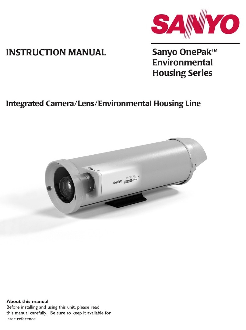
  9. Sanyo VDC-DP7585P User manual

Sanyo VDC-DP7585P User manual

Other manuals for VDC-DP7585P

2

This manual suits for next models

1

Other Sanyo Security Camera manuals

Sanyo VCC-WD8574 User manual

Sanyo

Sanyo VCC-WD8574 User manual

Sanyo VCC-ZM400 User manual

Sanyo

Sanyo VCC-ZM400 User manual

Sanyo VCC-3944 - 1/4" Color CCD DSP Camera User manual

Sanyo

Sanyo VCC-3944 - 1/4" Color CCD DSP Camera User manual

Sanyo VCC-HD2100 - Full HD 1080p Network Camera User manual

Sanyo

Sanyo VCC-HD2100 - Full HD 1080p Network Camera User manual

Sanyo VCC-6592PC User manual

Sanyo

Sanyo VCC-6592PC User manual

Sanyo VCB-3444 User manual

Sanyo

Sanyo VCB-3444 User manual

Sanyo VCC-6584DN - CCTV Camera User manual

Sanyo

Sanyo VCC-6584DN - CCTV Camera User manual

Sanyo VDC-C1574VA - CCTV Camera User manual

Sanyo

Sanyo VDC-C1574VA - CCTV Camera User manual

Sanyo VCC-HD4000 - Network Camera User manual

Sanyo

Sanyo VCC-HD4000 - Network Camera User manual

Sanyo VCC-5995P User manual

Sanyo

Sanyo VCC-5995P User manual

Sanyo VCC-5974 User manual

Sanyo

Sanyo VCC-5974 User manual

Sanyo VCC-WB4000P User manual

Sanyo

Sanyo VCC-WB4000P User manual

Sanyo VCC-3924 User manual

Sanyo

Sanyo VCC-3924 User manual

Sanyo VCC-P7575P Pan-Focus User manual

Sanyo

Sanyo VCC-P7575P Pan-Focus User manual

Sanyo VCC-MCH5600P User manual

Sanyo

Sanyo VCC-MCH5600P User manual

Sanyo VDC-DP9584S User manual

Sanyo

Sanyo VDC-DP9584S User manual

Sanyo VCC-5974P User manual

Sanyo

Sanyo VCC-5974P User manual

Sanyo VPC-MZ1E User manual

Sanyo

Sanyo VPC-MZ1E User manual

Sanyo VCB-3574IR User manual

Sanyo

Sanyo VCB-3574IR User manual

Sanyo VDC-D1785IRVP User manual

Sanyo

Sanyo VDC-D1785IRVP User manual

Sanyo VDC-D1785IRVP User manual

Sanyo

Sanyo VDC-D1785IRVP User manual

Sanyo VCC-XZ200P User manual

Sanyo

Sanyo VCC-XZ200P User manual

Sanyo VCC-9250P User manual

Sanyo

Sanyo VCC-9250P User manual

Sanyo VCC-3924P User manual

Sanyo

Sanyo VCC-3924P User manual

Popular Security Camera manuals by other brands

ADEMCO RapidDome Owners Operating & Installation Guide

ADEMCO

ADEMCO RapidDome Owners Operating & Installation Guide

EverFocus EBA2880 user manual

EverFocus

EverFocus EBA2880 user manual

Honeywell OptiCAM-IR Installation and setup guide

Honeywell

Honeywell OptiCAM-IR Installation and setup guide

Uniq UC-600 user manual

Uniq

Uniq UC-600 user manual

OPTICOM NVD-120-S datasheet

OPTICOM

OPTICOM NVD-120-S datasheet

Steren CCTV-221 instruction manual

Steren

Steren CCTV-221 instruction manual

Arm Electronics C420BCDNVFIR Features

Arm Electronics

Arm Electronics C420BCDNVFIR Features

Eneo PLD-2036PTZ installation guide

Eneo

Eneo PLD-2036PTZ installation guide

Axis AXIS M20 Series installation guide

Axis

Axis AXIS M20 Series installation guide

Panasonic KX-HCM230 operating instructions

Panasonic

Panasonic KX-HCM230 operating instructions

COP-USA CC15NV-SL Specifications

COP-USA

COP-USA CC15NV-SL Specifications

Active Silicon HARRIER H.264 quick start guide

Active Silicon

Active Silicon HARRIER H.264 quick start guide

Motorola Avigilon 1.3C-H5SL-BO1-IR installation guide

Motorola

Motorola Avigilon 1.3C-H5SL-BO1-IR installation guide

INSTEON 2864-232 user manual

INSTEON

INSTEON 2864-232 user manual

Wisenet XNB-6002 quick start guide

Wisenet

Wisenet XNB-6002 quick start guide

Axis M5525-E user manual

Axis

Axis M5525-E user manual

Vitek VTC-IR62NZ922 user guide

Vitek

Vitek VTC-IR62NZ922 user guide

Panasonic WV-SF342 Specifications

Panasonic

Panasonic WV-SF342 Specifications

manuals.online logo
manuals.online logoBrands
  • About & Mission
  • Contact us
  • Privacy Policy
  • Terms and Conditions

Copyright 2025 Manuals.Online. All Rights Reserved.

VDC-DP7584
VDC-DP7585P
Do not touch the lens and lens tube:
The lens and lens tube are composed of precision parts
that must be strictly kept untouched.
1Remove the lens assembly.
1Loosen the four screws (A) using the supplied hexagonal
wrench (large) (B) to remove the dome cover and the lens
cover.
2Pull off the pin connector cables from CN401, CN403 and
CN406.
3While holding the spring (C), pull the retainer (D) until it clicks.
2Install the camera unit base on the
ceiling or wall.
1Make four screw holes and a cable hole in the supplied
cushioning sheet (E) using the supplied pattern sheet, and
then attach it to the back of the camera unit base.
• When routing the cables on the ceiling or the wall, open the
conduit hole cover (F) after removing a screw (G) using
supplied hexagonal wrench (small) (H) and pass the cables
through the conduit hole.
2Make four screw hole marks (and a cable hole mark) on the
ceiling or the wall using the pattern sheet, and then drill the
screw holes (and cut a cable hole).
3Pass the cables (I) through the cable hole and match the four
screw holes of both the camera unit base and the ceiling or
the wall. And then, secure it using the four or more screws (J)
through the washers.
3Replace the lens assembly on the
camera unit base.
1Put the lens assembly back in its original position, then press
the retainer back into its original position.
2Plug the pin connector cables to CN401, CN403 and CN406.
4Make required
connections, and check
the image from the camera.
1Refer to “CONNECTIONS” on the back.
2Connect the MONITOR OUT pin and the
GND pin on the base circuit board to a
monitor using an alligator clip cable.
3Holding in the manner shown on the right,
move the lens in the pan and tilt directions
and check the image on the monitor.
Note:
When the image is displayed upside down, fold
the lens assembly downward and turn it to the
left to avoid damage to the FFC cable.
5Carry out the settings and
adjustment for the camera
using the on-screen menu.
Refer to the separate-volume instruction manual.
6Secure the dome cover by tightening the
screws (A).
If a whole surface of the camera’s lens does not show through
the camera window, loosen the screw (K) and adjust the dome
liner.
Note:
• When monitoring lighting or other extremely bright objects (which
exceed the maximum required illumination), smearing may occur in
the vertical or horizontal direction (either above and below the
high-brightness object or as a perpendicular band). In such a case,
adjust the angle of illumination and other factors while observing the
monitor.
• When installing the camera, make sure to properly perform
waterproofing for the holes in the ceiling or the wall.
• When setting up this camera, make sure that it is installed securely.
Check that the installation location is strong enough to bear the
camera weight before proceeding. Install to the ceiling or a wall that
has no surface unevenness. And be sure to embed the screw into the
ceiling or wall to a depth of at least 35 mm and a diameter of at least
3.5 - 5 mm. If the screw holes are too shallow, the camera may fall
down. In addition, do not touch the camera unit except when settings
and adjustments are necessary.
• Install where the temperature range will stay between –10°C (14°F)
and 50°C (122°F). (No condensation)
• The camera unit can be installed with the dome cover pointing
upward.
• If operated in an environment where the temperature may fall below
–10°C (14°F), attach the heater option board (VA-50H) to this camera
unit.
(K)
(A)
(B)
(C)
(D)
CN401
CN403
CN406
Lens assembly
Lens cover
Dome cover
Camera
window Dome liner
Camera window
Lens/Lens tube
(E)
(J) (J)
(I)
(H)
(G)
(F)
GND
MONITOR
OUT
INSTALLATION MANUAL
Color CCD Camera
●For the customers in US and Canada
THIS INSTALLATION SHOULD BE MADE BY A QUALIFIED SERVICE PERSON AND SHOULD CONFORM TO
ALL LOCAL CODES.
☞Please read this manual before installing and using this camera, and always follow the instructions in it for
proper use.
English
L5BH2(INSTALL).book 1 ページ 2006年3月1日 水曜日 午前11時41分
CONNECTIONS
Be sure to attach the supplied clamping core to the cables
as illustrated.
• On the cable for power supply
■Connection for Alarm Input
Refer to the instruction manual for the connected alarm device
for further details.
■Connection for Zoom Input
It is used to make wide angle/telescoping adjustments.
■Setting Color or Black-and-White
You can fix the image either to color or black-and- white using an
external switch, etc.
• Be sure to select “COLOR” for the “DAY/NIGHT” option in the
main menu (See page 23 on the INSTRUCTION MANUAL).
■Using a Camera Control Unit
When using menus, connect a camera control unit (VAC-70:
Separately ordered) because menu settings can be carried out
without removing the dome cover.
Do not connect the power cord until all other
connections have been completed.
Basic Connection for Monitoring and
Power Supply
To prevent electromagnetic interference
~~
GND
+–
• When using an RG-59U (3C-2V)
cable, do not let it dangle in the air or
attach it to piping.
• If you use a cable other than the types
above, the image or sync signal will be
attenuated and will not be transmitted
correctly.
Cable type Length
RG-59U (3C-2V) 250 m max.
RG-6U (5C-2V) 500 m max.
RG-11U (7C-2V) 600 m max.
BNC type
AC 24 V connection DC 12 V connection
Check that polarity is correct.
18 AWG or more
Red
Black
White Black
Red
Connecting to Other Equipment
Note: Make sure to disconnect the unit after setting or adjustment is
completed.
External Alarm Input Signal
Alarm device
Purple Gray
Common
Orange Gray Blue Common
Zoom Input Signal
TELE WIDE
SYNC
BLC
IRIS
WHITE BALANCE
AGC GAIN
GAMMA
SHUTTER
APERTURE
·DAY/NIGHT
OPTION
PRESET
MENU
INT
OFF
SET y
ATW
NORM
0.45
60
NORM
COLOR
SET y
OFF
END
External switch
Common
Gray
Yellow
Open: Color
Close: B/W
VAC-70
BNC type RG-6U (5C-2V) cable,
500 m max.
Printed on recycled paper
1AC6P1P3025--
L5BH2/US, XE (0206KP-SY) Printed in Japan
L5BH2(INSTALL).book 2 ページ 2006年3月1日 水曜日 午前11時41分