Sanyo 29-F5BA User manual

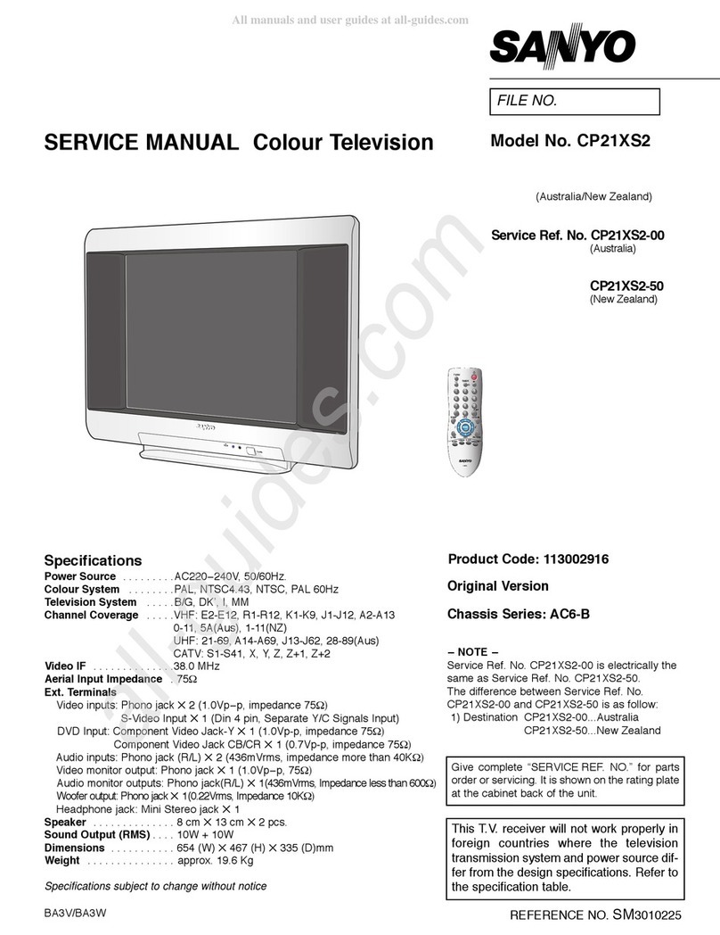
Specifications
Power Source . . . . . . . . .AC220V, 50Hz / 60Hz
Receiving System . . . . . .PAL (N/N, M/M), NTSC (M/M)
Channel Coverage
Antenna mode VHF: 02-13, UHF: 14-69
CATV mode VHF band: 01-13, Mid band: 14-22
Super band: 23-36, Hyper band: 37-94
Ultra band: 100-125
Low mid band: 01 and 95-99
Video IF . . . . . . . . . . . . .45.75MHz
Sound IF . . . . . . . . . . . .41.25MHz
Aerial Input Impedance . .75Ω
Ext.Terminals
Video inputs: Phono jack ✕2(1Vp - p, 75Ω)
S-Video terminal (DIN 4 pin, separate Y/C signal input) ✕1
Audio inputs: Phono jack (R/L) ✕2 (436mVrms, more than 40KΩ)
Video monitor outputs: Phono jack ✕1(1Vp - p, 75Ω)
Audio monitor outputs: Phono jack (R/L) ✕1 (436mVrms, less than 600Ω)
Variable Audio Output: Phono jack (R/L) ✕1 (less than 1 KΩ)
Sound Output (RMS) . . .5W + 5W
Dimensions . . . . . . . . . .768(W) ✕617.5(H) ✕487(D)mm
Weight . . . . . . . . . . . . . .approx. 35.7Kg
Specifications subject to change without notice.
Product Code: 1 113 338 00
Original Version
Chassis Series: LB1-A
F5BA/F5BAS
Give complete “SERVICE REF. NO.” for parts
order or servicing.It is shown on the rating plate
at the cabinet back of the unit.
This T.V. receiver will not work properly in
foreign countries where the television
transmission system and power source dif-
fer from the design specifications. Refer to
the specification table.
VIDEO POWER
DISPLAY CH-RECALL
123
456
789
0
CH
VOL
VOL
IMAGE
MENU
MUTE
SLEEP
CH
JXVD
SERVICE MANUAL Colour Television
FILE NO.
Model No. 29-F5BA
Service Ref. No. 29-F5BA-00
29-F5BA-01
(Argentina)

Contents
-2-
Safety Notice . . . . . . . . . . . . . . . . . . . . . . . . . . . . . . . . . . . . . . . . . . . . . . . . . . . . . . . . . . . . . . . . . . . . . . . . 2
Chassis Block Diagram . . . . . . . . . . . . . . . . . . . . . . . . . . . . . . . . . . . . . . . . . . . . . . . . . . . . . . . . . . . . . . 3-4
IC Block Diagrams . . . . . . . . . . . . . . . . . . . . . . . . . . . . . . . . . . . . . . . . . . . . . . . . . . . . . . . . . . . . . . . . . . 5-8
Service Adjustments . . . . . . . . . . . . . . . . . . . . . . . . . . . . . . . . . . . . . . . . . . . . . . . . . . . . . . . . . . . . . . . .9-10
Service Information . . . . . . . . . . . . . . . . . . . . . . . . . . . . . . . . . . . . . . . . . . . . . . . . . . . . . . . . . . . . . . . . . . 10
Adjustment in the Service Mode . . . . . . . . . . . . . . . . . . . . . . . . . . . . . . . . . . . . . . . . . . . . . . . . . . . . . . 11-14
Mechanical Disassemblies . . . . . . . . . . . . . . . . . . . . . . . . . . . . . . . . . . . . . . . . . . . . . . . . . . . . . . . . . . . . . 15
Cabinet Parts List . . . . . . . . . . . . . . . . . . . . . . . . . . . . . . . . . . . . . . . . . . . . . . . . . . . . . . . . . . . . . . . . . . . 16
Chassis Electrical Parts List . . . . . . . . . . . . . . . . . . . . . . . . . . . . . . . . . . . . . . . . . . . . . . . . . . . . . . . . . 17-26
Safety Notice
SAFETY PRECAUTIONS
1: An isolation transformer should be connected in the
power line between the receiver and the AC line
when a service is performed on the primary of the
converter transformer of the set.
2: Comply with all caution and safety-related notes pro-
vided on the cabinet back, inside the cabinet, on the
chassis or the picture tube.
3: When replacing a chassis in the cabinet, always be
certain that all the protective devices are installed
properly, such as, control knobs, adjustment covers
or shields, barriers, isolation resistor-capacitor net-
works etc.. Before returning any television to the
customer, the service technician must be sure that
it is completely safe to operate without danger of
electrical shock.
X-RADIATION PRECAUTION
The primary source of X-RADIATION in television receiver is the picture tube. The picture tube is specially con-
structed to limit X-RADIATION emissions. For continued X-RADIATION protection, the replacement tube must be
the same type as the original including suffix letter. Excessive high voltage may produce potentially hazardous X
- RADIATION.To avoid such hazards, the high voltage must be maintained within specified limit.Refer to this ser-
vice manual, high voltage adjustment for specific high voltage limit. If high voltage exceeds specified limits, take
necessary corrective action.Carefully follow the instructions for + B1 volt power supply adjustment, and high volt-
age check to maintain the high voltage within the specified limits.
PRODUCT SAFETY NOTICE
Product safety should be considered when a component replacement is made in any area of a receiver.
Components indicated by mark in the parts list and the schematic diagram designate components in which
safety can be of special significance. It is particularly recommended that only parts designated on the parts list
in this manual be used for component replacement designated by mark . No deviations from resistance
wattage or voltage ratings may be made for replacement items designated by mark .
Chassis Block Diagrams (Main Signal Processing Circuit)
-3-
IC802
MEMORY
BUS SDA
BUS SCL
5
6
2
3
IC801
CPU
23
24
27
28
29
A101
TUNER
IC201
IF/VIDEO/CHROMA
SIF
FILTER
4.5MHz
32
8
18
1
19
47/48 35
34
33
14
13
31
30
29
10
51
25
16
R (OSD)
G (OSD)
B (OSD)
SOUND
CARRIER
TRAP
4.5MHz
ANALOGUE-BUS DATA
ANALOGUE-BUS ADDRESS
SIF IN
IF IN
VIDEO OUT
(WITH SIF CARRIER)
INT. VIDEO IN
B IN
R IN
G IN
S-CHROMA IN
7
31
IC1101
AV SW
AV2 VIDEO
AV1 VIDEO
IC001
AUDIO
AMP.
8
10
5
1
37 40
41
25
26
39
38
23
22
7
36
AUDIO OUT
SP901
SP902
R-OUT
L-OUT
L R
VARIABLE
AUDIO OUT
(REAR)
L R V
MONITOR OUT
(REAR)
IC3401
MTS DECODER
R-OUT
L-OUT
SDA
SCL
V L R
AV2 INPUT
(FRONT)
V L R
AV1 INPUT
(REAR)
S-CHROMA
Y
S-TERMINAL
POWER
SUPPLY
CIRCUIT
AC
IC651
REG. 5V
13
15V
9V
30V (AUDIO)
130V
(MAIN HIGH)
24V (VERT.)
T611
CONVERTER
TRANS.
IIC BUS
R
-
Y
-
Y
B
-
Y
G
-
Y
R
OUT
B OUT
G OUT
Q705
Q701
Q703 Q901
CRT
IC501
VERT. OUT
Q431 Q432 FOCUS
SCREEN
T451
FBT
DY
20 VERT. DRIVE 12
2
VERT. DY
HORIZ. DY
HORIZ.
DRIVE
VIDEO MONITOR OUT
H.V.
EXT. VIDEO
IN
HORIZ.
DRIVE HORIZ.
OUT
X161
SAW FILTER
39
36
37
38 7
3
1
5
R
-
Y
B
-
Y
R
-
Y
B
-
Y
IC271
1H DELAY

-4-
IC801
CPU
32
ON-TIMER LED DRIVE
2
3
IC802
MEMORY
7
8
X'TAL SW-1
X'TAL SW-2
TO IC201
POWER ON/OFF 1
10
11
X'TAL
OSC for
CPU
13
AFT SIGNAL IN
15
KEY SCAN IN
KEY SWITCHES
16
OPTION SW IN
17
RESET IN
18
19
OSC for
OSD
23
ANALOGUE BUS DATA
24
ANALOGUE BUS ADDRESS
TO IC201
25
26
V-PULSE IN
H-PULSE IN
Q816
Q815
Q817
POWER
SUPPLY
CIRCUIT
D1003
Q681
24V
Q661
9V
D683
41
POWER FAILURE
DETECTION
VERTICAL
DEFLECTION
FLYBACK
TRANS.
D483
D500
POWER FAILURE
Q691
A101
TUNER
IC201
IF/VIDEO/
CHROMA
IC3401
MTS
DECODER
IC001
AUDIP
AMP.
52 PLL ENABLE OUT
(ENABLE=HIGH)
5PLL CLOCK OUT
6PLL DATA OUT
IF IN
51 CAPTION ENABLE (ENABLE=LOW)
49 PIP ENABLE (ENABLE=LOW)
48 CAPTION OPTION (CAPTION=LOW)
47 PIP OPTION (PIP=LOW)
46 IF IDENT IN (NO SIGNAL=LOW)
44 RC SIGNAL IN (ACTIVE=LOW)
43 COLOR KILLER IN (COLOR ID=HIGH)
42 SYNC. ID IN (NO SYNC.=HIGH)
45
AC SWITCH OPTION
(MECHA.SW=LOW, SOFT SW=HIGH))
40 TV/AV SW OUT (TV=LOW)
39 AV1/AV2 SW OUT (AV1=HIGHT)
35 RELAY ON/OFF FOR DEGAUSSING COIL OUT
34 SOUND MUTE OUT (MUTE=HIGH)
30 BLANKING OUT
29 OSD B-OUT
28 OSD G-OUT
27 OSD R-OUT
AUDIO
AUDIO
Chassis Block Diagrams (System Control)

IC Block Diagrams
-5-
LA7687N < IF/Video/chroma/Def. > IC201
APC
DET
LIM
AMP
FM
DET
IDENT
INT/EXT
RF
AGC
AG
AGC
DEF COIN
BUZZ
CANCEL
VIDEO
DET
VCO AFT
VIDEO
AMP
AV-SW
SECAM
VIF
AMP
ACC
KILLER
S-SW
V-SW
C-BPF
SWITCH
1ST
BPA
APC
VCO
2ND
BPA
TINT
FILTER
ADJUST C-TRAP
DELAY
APA-CON
(YNR)
IDENT
X-TAL
IDENT
DET
F/F
PAL
SW
MEMO
RB OUT
ADD
LPFALC
CONT-
RAST
V/C
BUS
OSD SWITCH
RBAMP
G-Y MATRIX
BRIGHT
CLAMP
SYNC
SEP
VER
SYNCSEP
VER
C/D
IDENT
DET
H & V
BLANK
OSD
AFC 1
HOR
C/D
HOR
OSC
CLOCK
OUT
AFC 2
PHASE
SHIFTER F.B.P.
DET
HOR
DRIVER
LA7687
1 2 3 4 5 6 7 8 9 10 11 12 13 14 15 16 17 18 19 20 21 22 23 24 25 26
37 36 35 34 33 32 31 30 29 28 2743 42 41 40 39 38
45 4451 50 49 48 47 4652
AV-SW/SECAM
ID OUT
AFT OUT
ACL
S-SW
S-CHROMA
EXT-VIDEO
VCC 5V
KILLER
BUS 1
BUS 2
V-OUT
50/60Hz
H-VCC
FBP
SC
COIN
BLK-IN
B-IN
G-IN
R-IN
-Y OUT
B-Y OUT
G-Y OUT
R-Y OUT
V/C
VCC
CCD 1H DL
L-SECAM
A-OUT
RFAGC
VIF IN
SAW
IFAGC
IF GND
GND
4.5MHz
5.5MHz
3.58MHz
4.43MHz
R-Y OUT
B-Y OUT
R-Y IN
B-Y IN
ABL
VIDEO OUT
SOUND
TRAP
9.5MHz

IC Block Diagrams
-6-
LC89950 < IH DL > IC271
LC89950
CLAMP
AUTO-BIAS
AUTO-BIAS
CLAMP
BGP
BGP
CCD
254.5bit
ø1 ø2
CCD
254.5bit
ø1 ø2
4MHz OUT
DUTY
COMPENSATION
CLOCK DRIVER
TIMING
GENERATOR
VCO 256 DIVIDER PHASE
COMPARATOR
PULSE SHAPER
BGP
DETECTOR
BGP
OUTPUT
S&G, AMP
LEVEL
INCREASER
OUTPUT
S&G, AMP
B-Y
IN
Vdd
R-Y
IN
4MHz
OUT
COMP
VCO IN PC OUT
Vdd
BGP IN
R-Y OUT
RD
B-Y OUT
Vss
5
6
7
8
9
10 11
12
13
1
2
3
4
Vss
14
LA7838 < V-OUTPUT > IC501
VERT.
TRIGGER
INPUT
ONE SHOT
MULTI
RAMP
GENERATOR
V-SIZE
CONTROL
SWITCH
DRIVE
THERMAL
PROTECTION
OUTPUT
PUMP UP
1234 5 6 7 8 9 10 11 12 13
LA7837
Vcc1 Vcc2
DY
Vcc2
FEED BACK
V.TRIGER
INPUT
50/60HZ SW.

IC Block Diagrams
-7-
7
12
8
910 11 15 18 14 13 17 16 20
Noise BPF
Noise
Detector I2C Bus
Interface
SAP Demodulation Block
Composite
Signal Input
2.2µF
0.1µF
0.047µF
SAP Signal
Detector
SAP Offset
Absorption
0.47µF0.1 µF
68KΩ
5.1
KΩ
16.6
KΩ
Noise
Detector
+
+
+
23 22
24 46 3
5
4.7µF
1µF
0.1µF
+
1KΩ
2
22µF
+
1/2Vcc
42
1µF
+
34 35 38 36 39 37 41 40
Filter
Control
Stereo
Demodulation
Block fH
LPF fH
Trap
Switch
75µS
De-emphasis Offset
Absorption
dbx Noise
Reduction
Block
Matrix Selector
Block
Surround
Block
Tone Control Block
Volume Control Block
33 32 31
26
25
21
28
29
302719
1
2.2µF
+
0.1µF 2200pF
+Vcc
+
+
10 µF
10 µF
D/A
2.2µF
+
0.1µF
+
2200pF
0.022µF
4.7µF
+
1 µF
+
10 µF
+
3.3 µF
+
1 µF
+
1 µF
+
3
KΩ
1 µF
+
D/A
Input
Attenuator
I2C Bus
Interface D/A
Filter
Power Supply
Reference Voltage
Pilot Detector 1
Pilot Detector 2
Phase
Detector 1
Phase
Detector 2
SAP Signal Output
SAP Signal Input
Spectral Timing Setting
VCA Offset Absorption
Wide-band Timing Setting
Wide-band RMS Setting
Spectral RMS Setting
Variable Emphasis Input
Offset Absorption
Variable Emphasis
Offset Absorption
Analog Ground
Timing Current Setting
SDA
SCL
GND(I2Cbus)
R-channel
Output
L-channel
Output
Surround Timing Setting
R-channel Offset
Absorption
R-channel Capacity of
High Frequency Band Width
R-channel Capacity of
Low Frequency
Band Width
L-channel Offset
Absorption
L-channel Capacity of
High Frequency
Band Width
L-channel Capacity of
Low Frequency
Band Width
External R-channel Input 3
External L-channel Input 3
External R-channel Input 1
External R-channel Input 2
External L-channel Input 1
External L-channel Input 2
L-channel Fixed Output
Monaural Offset Absorption
R-channel Fixed Output
UPC1851< MTS> IC3401

IC Block Diagrams
-8-
STR81145A < Double Rectifier > IC631
23
Pin Function
1 Delay
2 T1
3 T2
4 Gate
5 Common
4
5
1
STR81145A
r1
r2 r3
Z1
Q1
Z2
Q3
Q2
Triac
1
2
3MUTE
REFERENCES
NON INVERTING INPUT (1)
INVERTING INPUT (1)
SUR/MUTING
TURN ON
AND OFF
9
5
10
8
4
6
Vcc
NON INVERTING INPUT (2)
INVERTING INPUT (2)
L
R
-
+
-
+
GND
RF I 27K
RF I 27K
SC
PROTECTION
Tj
TH
PROTECTION
OUTPUT-L
OUTPUT-R
TDA7263M
TDA7263M < AUDIO AMP. > IC001

-9-
Service Adjustments
(E BB)
Q251
KB
TP-G TP-H
VR465
H-WIDTH
VR510
V-SIZE
R436
L430
T431
Q431
HORIZ.
DRIVE
Q432
HORIZ. OUT
L430
T451
F.B.T.
FOCUS SCREEN
KDY
L441
L472
IC501
VERT.
OUT
Q526
C521
Q462
Q461
C510 C515
KZ
K1111
AUDIO IN VIDEO IN
(R) (L)
C631
C632
IC631
L602
PS602
R632
R631
RL640
L601
KE
Q613
POWER
SWITCHING
F601
KAC
Q612
POWER
DRIVE
Q611
Q693
D615
Q692
C652
C672
Q681
Q651
VR651
+B ADJ.
KL KM
Q141 Q140 Q202 Q201
Q691
Q252
Q861
Q862
Q021
Q684
Q111
Q243 Q242 Q261
AV BOARD
IC3401
MTS
KI
KY
IC1101 Q661
C017
IC001
AUDIO
AMP.
IC201
IF/VIDEO/CHROMA
KU
VR191
AGC
KQ
TP-D
X131 X141
TP-A L171
KP
Q131
L161
X242
X161
A101 TUNER
VR351
H-CENTER
X243
X241
IC201
1H DELAY
IC651
KS
KG
KJ
Q852
Q815
Q871
Q816 Q817
Q646
IC803
X801
IC802
MEMORY
IC801
CPU
KC
KN
KA KAA
KH
KD
T611
CONVERTER
TRANS.
SW1902 SW1903 SW1904 SW1905 SW1906
VOL. + MENUCH DOWN
CH UPVOL.
-
R528
R527
TP-B
D651
Horizontal Centring Adjustment
1. Receive the mono-chrome circular pattern.
2. Adjust VR351 for optimum horizontal centre
position. Horizontal Centre
Vertical Centring Adjustment
1.Tune the receiver to an active channel. Check that the picture is in the
centre of TV screen.
2. If the picture is too low, change a resistor R528 from 1KΩ, 1/2W to 470Ω,
1W. If the picture is too high, delete a resistor R528 (1KΩ, 1/2W).
Vertical centre
Horizontal Width Adjustment
1. Receive the mono-chrome
circular pattern.
2. Adjust V465 for optimum
horizontal width.
RF AGC Adjustment
1.Tune the receiver to most clearest (or strongest) VHF station
in your area.
2. Set the brightness and contrast control to maximum. Set the
colour control to minimum.
3.Turn AGC control (VR191) in the direction which causes
snow to appear, then in the opposite direction until the snow
just disappears.
+B Power Supply Adjustment
1. Connect DC volt-meter to “TP-B” and the ground. Set the +B adjustment
control (VR651) to mid-range. (Mains voltage AC220 ± 2 volt)
2. Set brightness and contrast to minimum.Tune the receiver to an active
channel and synchronized picture.
3. Adjust +B adjustment control (VR651) for 130 ± 1.0 volt DC.
Focus Adjustment
Adjust focus control for well
defined scanning lines.
Vertical Size Adjustment
1.Tune the receiver to the mono-chrome circular
pattern.
2. Adjust vertical size control (VR510) for full scan.

-10-
Service Adjustments
This TV set has a built-in power supply protection circuit.
It is provided to protect the TV set in case of a power supply circuit malfunctions.When something abnormality
occurs during TV reception, the TV set goes to the stand-by mode.
When an abnormality occurs duringTV reception, it causes pin 41 of the CPU to go continually Low(less than
0.75V) for about one second. The CPU detects that this has occurred and outputs the signal from pin 1 to
switch off the power oscillation circuit.
■Releasing the protective circuit and restoring power supply
To release the protective circuit and restore power supply, turn the power to theTV set OFF and then ON again
via either the main power switch or the ON-OFF button on the remote control.This will work only if the power
supply trouble was temporary. If there is permanent trouble such as a damaged circuit, power cannot be
restored and the circuit will have to be repaired.
Service information
■Protection Circuit
TP-G TP-H
VR465
H-WIDTH
VR510
V-SIZE
Q431
HORIZ.
DRIVE
L430
T451
F.B.T.
FOCUS SCREEN
Q701
B-OUT
Q705
R-OUT
Q703
G-OUT
K7Y1
SW701
NORMAL SERVICE
K701
CRT SOCKET
VR703
BLUE BIAS
VR702
GREEN BIAS
VR701
RED BIAS
VR705
BLUE DRIVE
VR703
RED DRIVE
Gray Scale Adjustment
1. Receive the mono-chrome circular pattern.
2. Set the picture mode to “NORMAL” mode by
pressing the IMAGE button on the remote control.
NORMAL
3. Set the service switch (SW701) on the CRT board to
“SERVICE” position.
4. Set RED (VR704) and BLUE (VR705) drive controls
to mid position. Set BLUE (VR703), GREEN (VR702)
and RED (VR701) bias controls to minimum (fully
counterclockwise).
5.Turn the SCREEN control on the F. B.T. to obtain just
visible one coloured line.
6. Adjust each bias control alternately until a dim white
line produced.
7. Set the service switch (SW701) to “NORMAL”
position.
8. Adjust RED and BLUE drive controls alternately to
produce normal black and white picture in highlight
areas.
9. Check for proper gray scale at all brightness levels.
Note: If the gray scale adjustments is made after pic-
ture tube replacement, check the brightness level
adjustment.
(MAIN BOARD)
(CRT BOARD)
Grey Scale Adjustment

Adjustments in the Service Mode
-11-
Since some chassis circuit adjustments are controlled by the CPU built into the chassis, adjustments can be made
by inputting data directly via the remote control handset supplied with set.
[Memory IC replacement]
Since adjustment data for the circuit is stored in the memory IC (IC802) that comes with the CPU, the initializing of
the memory IC and re-inputting of the adjustments data must be made when the memory IC is replaced.
■Initializing of the Memory IC
1. Replace IC 802.
2. Switch the TV on.
3. Press and hold the MENU button on the TV set, then
press “0” button on the remote control transmitter.
O-R MENU CHA
0
Initial Data is as follows;
Adjustment Item Initial Data
INPUT LEVEL 25
STEREO VCO 23
FILTER 32
LOW SEPARATION
HI SEPARATION
SAP VCO
29
26
27
[MTS Adjustment Data]
[3 Steps Picture Mode Normalization Data]
COLOR
CONTRAST
BRIGHTNESS
STRONG NORMAL SOFT
34
63
15
30
63
32
22
63
40
■Service mode adjustments
To enter to the service mode, press and hold the MENU button, then press the NUMERIC button (1, 2, 3 or 4).
Each service modes are as follows;
TV set Remote control button
MENU
button
Digit "1"
Digit "2"
Digit "3"
Digit "4"
Item
3 steps picture mode normalization
Sub-Brightness/Sharpness Adjustment
Stereo Adjustment
Fine Tuning mode
When the memory IC is replaced, Sub-Brightness and MTS adjustments should be-adjustments according to
service mode adjustments described below.
Sub-Brightness Adjustment
NOTE: AGC and Gray Scale must be adjusted before attempting the Brightness
Level Adjustment.
1. Receiver the mono-chrome circular pattern.
2. Connect the DC voltmeter “+” lead to TP-H and “-” lead to TP-G on the main
board.
3. Press and hold the MENU button on the TV set, then press “2” button on the
remote control transmitter to enter the Service Mode.
TP-G TP-H
VR
V-S
Q431
HORIZ.
DRIVE
T451
F.B.T.
FOCUS SCREEN
DC Volt Meter
O-R MENU CHA
2
4. Adjust the voltage to become DC 750mV ± 20mV by pressing the VOLUME (+/-) button on the
remote control or TV set.
5. Press the MENU button to return to the normal TV mode.
Note: Check the brightness level in every active channels, readjust if necessary.
SUB-BRIGHT 32
SUB-SHARPNESS 31
ADJUST: - /+
CHOOSE: ▲▼ EXIT:MENU
(Service Mode)

Q141 Q140 Q202 Q2
Q
Q111
Q243 Q242
IC3401
MTS
IC110
IC201
IF/VIDEO/CHROMA
VR191
AGC
TP-D X141
TP-A
L171
KP
Q131
X242
X161
A101 TUNER
X243
X241
IC201
1H DELAY
KS
Base
TP20
TP301
C3407
TP317
C3437
Frequency
Counter
Ground with
jumper wire
GND
MAIN BOARD
Adjustment in the Service Mode
-12-
Sound Input Level Adjustment
1. Connect a signal generator to TP301 (C3407, - side) on
the Main Board and ground. Signal output=300Hz, 150mVrms.
2. Connect a DC Volt-Meter to TP-317 (C3437, + side) and
ground.
3. Ground TP-20 (base of Q131) with the jumper lead. (Setting
of the no signal condition).
4. Switch the TV set on.
Press and hold the MENU button on the TV set, then press
“3” button on the remote control transmitter to enter the
Service Mode.
(Service Mode)
5. Adjust voltage to become DC 500mVrms±10mVrms by
pressing the VOLUME(+/-) button on the remote control or
TV set.
6.To exit from the service mode, press the MENU button.
Stereo VCO Adjustment
1. Connect a frequency counter to TP317 (C3437, + side) and
ground.
2. Ground C161 with the jumper lead.
3. Switch the TV set.
Press and hold the MENU button on the TV set, then press
“3” button on the remote control transmitter to enter the
Service Mode.
4. Select “STEREO VCO” by pressing the CHANNEL
UP/DOWN button on the remote control or TV set.
O-R MENU
3
Q141 Q140 Q202 Q2
Q
Q111
Q243 Q242
IC3401
MTS
IC110
IC201
IF/VIDEO/CHROMA
VR191
AGC
TP-D X141
TP-A
L171
KP
Q131
X242
X161
A101 TUNER
X243
X241
IC201
1H DELAY
KS
Base
TP20
TP301
C3407
TP317
C3437
Signal
Generator
Volt Meter
Ground with
jumper wire
GND
GND
MAIN BOARD
O-R MENU
3
INPUT LEVEL 25
STEREO VCO 23
FILTER 32
LOW SEPARATION 29
HI SEPARATION 26
SAP VCO 27
ADJUST: - /+
CHOOSE: ▲▼ EXIT:MENU
(Service Mode)
INPUT LEVEL 25
STEREO VCO 23
FILTER 32
LOW SEPARATION 29
5. Adjust the frequency to become 15.625KHz ± 0.1KHz by pressing
the VOLUME (+/-) button on the remote control or TV set.
6.To exit from the service mode, press the MENU button.
INPUT LEVEL 25
STEREO VCO 23
FILTER 32
LOW SEPARATION 29
HI SEPARATION 26
SAP VCO 27
ADJUST: - /+
CHOOSE: ▲▼ EXIT:MENU

Q141 Q140 Q202 Q2
Q
Q111
Q243 Q242
IC3401
MTS
IC11
IC201
IF/VIDEO/CHROMA
VR191
AGC
TP-D X141
TP-A
L171
KP
Q131
X242
X161
A101 TUNER
X243
X241
IC201
1H DELAY
KS
Base
TP20
TP301
C3407
TP317
C3437
Signal
Generator
Volt Meter
Ground with
jumper wire
GND
GND
MAIN BOARD
IC3401
MTS
Q141 Q140 Q202 Q201
Q861
Q111
Q243 Q242 Q
KY
IC1101
Q
IC201
IF/VIDEO/CHROMA
VR191
AGC
TP-D X141
TP-A
L171
KP
Q131
X242
X161
A101 TUNER
X243
X241
IC201
1H DELAY
KS
Base
TP20
C3407
TP317
C3437
Oscilloscope GND
GND
(Probe-A)
(Probe-B)
C3438
TP318
MAIN BOARD
Adjustment in the Service Mode
-13-
MTS Filter Adjustment
1. Connect a signal generator to TP301 (C3407, - side) on
the Main Board and ground. Signal output=15.734KHz,
100mVrms.
2. Connect an Audio Volt-Meter to TP317 (C3437, + side) and
ground.
3. Ground TP-20 (base of Q131) with the jumper lead. (Setting
of the no signal condition.)
4. Switch the TV set on.
Press and hold the MENU button on the TV set, then press
“3” button on the remote control transmitter to enter the
Service Mode.
O-R MENU
3
INPUT LEVEL 25
STEREO VCO 23
FILTER 32
LOW SEPARATION 29
HI SEPARATION 26
SAP VCO 27
ADJUST: - /+
CHOOSE: ▲▼ EXIT:MENU
(Service Mode)
INPUT LEVEL 25
STEREO VCO 23
FILTER 32
LOW SEPARATION 29
HI SEPARATION 26
SAP VCO 27
5. Select “FILTER” by pressing the CHANNEL UP/DOWN
button on the remote control or TV set.
Stereo Separation Adjustment
1. Connect an oscilloscope:
Probe-A to TP317 (C3437, + side) on the Main Board.
Probe-B to TP318 (C3438, + side) on the Main Board.
2. Switch the TV set on, and receive the multi sound program.
3. Press and hold the MENU button on the TV set, then press “3”
button on the remote control transmitter to enter the Service
Mode.
4. Select “LOW SEPARATION” by pressing the CHANNEL
UP/DOWN button on the remote control or TV set.
INPUT LEVEL 25
STEREO VCO 23
FILTER 32
LOW SEPARATION 29
HI SEPARATION 26
SAP VCO 27
ADJUST: - /+
CHOOSE: ▲▼ EXIT:MENU
(Service Mode)
INPUT LEVEL 25
STEREO VCO 23
FILTER 32
LOW SEPARATION 29
HI SEPARATION 26
SAP VCO 27
O
-R MENU
3
6. Adjust voltage to become minimum reading by pressing the
VOLUME(+ -) button on the remote control or TV set.
7.To exit from the service mode, press the MENU button.

KL
Q140 Q202 Q201
Q861
Q684
Q111
Q243 Q242 Q261
A
IC3401
MTS KY
IC1101 Q661
IC201
IF/VIDEO/CHROMA
K
VR191
AGC
TP-D X141
TP-A
L171
Q131
X242
X161
A101 TUNER
VR3
H-CEN
X243
X241
IC201
1H DELAY
IC65
KS
Base
TP20
TP316
C3407
TP317
C3437
Frequency
Counter
Ground with
jumper wire
GND
MAIN BOARD
C3411
1M Ohms
Ground with jumper
lead through 1M ohms
resister.
Adjustment in the Service Mode
-14-
5. Adjust level of 300Hz at TP317 to become minimum by pressing the VOLUME(+ / -) button on the remote
control or TV set.
Minimum leakage
TP317 (R)
300Hz
6. Select “HI SEPARATION” by pressing the CHANNEL UP/DOWN button on the remote control or TV set.
7. Adjust level of 4KHz at TP318 to become minimum by pressing the VOLUME (+/-) button on the remote
control or TV set.
8.To exit from the service mode, press the MENU button.
SAP VCO Adjustment
1. Connect a frequency counter to TP317 (C3437, + side) on the
Main Board and ground.
2. Ground TP-20 (Base of Q131) with the jumper lead. (Setting
of no signal condition.)
3. Ground TP-316 (C3411, side +) with the jumper lead through
1M Ωresistor.
4. Switch the TV set on.
5. Press and hold the MENU button on the TV set, then press
“3” button on the remote control transmitter to enter to the
Service Mode.
6. Select “SAP VCO” by pressing the CHANNEL UP/DOWN
button on the remote control or TV set.
7. Adjust frequency of the counter to become 78.125KHz ±0.5KHz
by pressing the VOLUME (+/-) button on the remote control or
TV set.
8.To exit from the service mode, press the MENU button.
TP318 (L)
Minimum leakage
4KHz
INPUT LEVEL 25
STEREO VCO 23
FILTER 32
LOW SEPARATION 29
HI SEPARATION 26
SAP VCO 27
INPUT LEVEL 25
STEREO VCO 23
FILTER 32
LOW SEPARATION 29
HI SEPARATION 26
SAP VCO 27

Mechanical Disassemblies
-15-
CABINET BACK REMOVAL
1. Refer to Figure-1, remove 11 screws.
2. Pull the cabinet back off and remove the cabinet back.
(MONO) AUDIO OUT
(VARIABLE)
L
R
VIDEO
R AUDIO L
VIDEO
AUDIO
INPUT
MONITOR
OUTPUT
S-VIDEO
VHF/UHF/CATV
75 INTERNAL
SPEAKERS
ON OFF
[ Figure-1. Cabinet Back Removal ]
CHASSIS REMOVAL
PICTURE TUBE REMOVAL
1. Remove the cabinet back.
2. Unplug degaussing coil socket (KE), anode lead, speaker socket (K12SP), deflection yoke (KDY), picture tube board
and picture tube ground leads.
3. Remove the chassis completely by sliding straight back.
CAUTION: Do not disturb the deflection yoke or magnet assembly on the picture tube neck. Care must be taken to
keep these assemblies intact, unless picture tube is being replaced. Discharge the picture tube’s coating
before handling the tube.
1. Remove the chassis.
2. Place the cabinet’s front down on a soft
surface.
3. Remove the screw on the earth corner of
the picture tube and gently remove the
picture tube from the cabinet.
4. Install a replacement picture tube in
reverse order. Referring to Figure-2,
properly install the degaussing coil and
the picture grounding lead on the picture
tube.
Note: If the picture tube is replaced mount
the degaussing coil properly on the tube.
See illustration.
Purity and Convergence
Adjustment
Purity and Convergence have
been aligned at factory no
realignment is necessary. [ Figure-2. Picture Tube Removal ]

-16-
F5BA/F5BAS
Cabinet Parts List
Note: Parts order must contain Service Ref. No., Part No., and descriptions.
(MONO) AUDIOOUT
(VARIABLE)
L
R
VIDEO
R AUDIO L
VIDEO
AUDIO
INPUT
MONITOR
OUTPUT
S-VIDEO
VHF/UHF/CATV
75 INTERNAL
SPEAKERS
ON OFF
1 610 266 5895 BUTTON POWER
610 210 7302 COIL SPRING
2 610 266 5918 DEC INLAY
3 610 289 6329 DOOR
4 610 104 2505 LATCH PUSH
5 610 103 8027 DUBBING BUTTON
6 610 274 2701 DEC CONTROL SHEET
7 610 266 5901 BUTTON UNITED
8 610 266 1248 CABINET FRONT
9 610 274 1889 CABINET BACK
10 610 289 6527 LABEL RATING
(Service Ref. No. 29-F5BA-00)
610 289 6534 LABEL RATING
(Service Ref. No. 29-F5BA-01)
11 610 274 2718 DEC REAR SHEET
12 645 027 5197 ASSY,REMOCON JXVD
13 610 271 3121 RC-BATTERY LID
14 645 004 5493 ANT MATCHING BOX
610 289 6404 INSTRUCTIONS MANUAL
Key No. Part No. Description Key No. Part No. Description
VIDEO POWER
DISPLAY CH-RECALL
12 3
4 5 6
7 8 9
0
CH
VOL
VOL
IMAGE
MENU
MUTE
SLEEP
CH
JXVD
VIDEO L-AUDIO-R MENU CHANNEL VOLUME AC SW
12
3
4
5
6
7
9
10
11
12
13
14
8

-17-
F5BA
OUT OF CIRCUIT BOARD
PICTURE TUBE
Q900 414 008 5309 CRT A68AGA25X401
COIL
L901 610 226 8058 DEGAUSSING COIL
610 228 2801 DEGAUSSING COIL
610 229 4200 DEGAUSSING COIL
MISCELLANEOUS
SP901 610 236 5016 SPEAKER
SP902 610 236 5016 SPEAKER
WFO 610 246 9936 CORD,FOCUS
WSC 610 247 0048 CORD,SCREEN
W900 610 265 8910 ASSY,WIRE GND CONNECTOR F
W901 645 005 2019 CORD,POWER-2.4MK
W903 610 253 4610 ASSY WIRE,DY CONECTOR G3B
610 276 7346 ASSY WIRE,DY CONECTOR E7B
610 232 9803 (USA)CORD
610 265 3274 ASSY,PWB,AV E7BA
1AA0B10E338A0
RESISTOR
R1202 401 027 6608 CARBON 75 JA 1/6W
R1207 401 024 7707 CARBON 100K JA 1/6W
R1208 401 027 5007 CARBON 68 JA 1/6W
R1209 401 024 7707 CARBON 100K JA 1/6W
R1211 401 024 7707 CARBON 100K JA 1/6W
R1212 401 027 2303 CARBON 560 JA 1/6W
R1213 401 027 2303 CARBON 560 JA 1/6W
R1214 401 026 4308 CARBON 3.3K JA 1/6W
R1215 401 026 4308 CARBON 3.3K JA 1/6W
R1216 401 027 5205 CARBON 680 JA 1/6W
R1217 401 027 5205 CARBON 680 JA 1/6W
DIODE
D1201 407 099 6201 ZENER DIODE MTZJ10C
407 054 0107 ZENER DIODE RD10EB3
MISCELLANEOUS
A1201 610 266 6311 TERMINAL BASE-F5BD
610 231 4670 JACK BASE-G3HCM
610 275 6081 JACK BASE-G3HCM-A
K1201 610 010 8295 SOCKET,DIN 4P
K1202 610 010 3689 JACK,RCA
K1203 610 010 3665 JACK,RCA
K1204 610 010 3672 JACK,RCA
K1205 610 010 3689 JACK,RCA
K1206 610 010 3665 JACK,RCA
K1207 610 010 3603 RCA JACK 1P
K1208 610 010 3665 JACK,RCA
K1209 610 010 3672 JACK,RCA
SW1201 645 022 0326 SLIDE SWITCH 2P-2T
!
!
!
Chassis Electrical Parts List
Ref. No. Part No. Description Ref. No. Part No. Description
Product safety should be considered when a component replacement is made in any area of a receiver.
Components indicated by a mark in this parts list and the circuit diagram show components whose value have
special significance to product safety. It is particularly recommended that only parts specified on the following parts
list be used for components replacement pointed out by the mark.
!
Note: Parts order must contain Service Ref. No., Part No., and descriptions. The main PCB unit will be supplied without tuner and
flyback transformer. They should be ordered separately.
Read description in the Capacitor and Resistor as follows:
CAPACITOR
CERAMIC 100P K 50V
Rated Voltage
Tolerance Symbols:
Less than 10pF
A : Not specified B : ±0.1pF C : ±0.25pF
D : ±0.5pF F : ±1PF G : ±2pF
R : ±0.25-0pF S : ±0-0.25pF E : +0-1pF
More than 10pF
A : Not specified B : ±0.1% C : ±0.25%
D : ±0.5% F : ±1% G : ±2%
H : ±3% J : ±5% K : ±10%
L : ±15% M : ±20% N : ±30%
P : +100-0% Q : +30-10% T : +50-10%
U : +75-10% V : +20-10% W : +100-10%
X : +40-20% Y : +150-10% Z : +80-20%
Rated value: P=pico farad, U=micro farad
Material:
CERAMIC...........Ceramic
MT-PAPER.........Metallized Paper
POLYESTER......Polyester
MT-POLYEST.....Metallized Polyester
POLYPRO..........Polypropylene
MT-POLYPRO....Metallized Polypropylene
COMPO FILM.....Composite film
MT-COMPO........Metallized Composite
STYRENE...........Styrene
TA-SOLID...........Tantalum Solid
AL-SOLID...........Aluminium Solid
ELECT................Electrolytic
NP-ELECT..........Non-polarised Electrolytic
OS-SOLID.......... Aluminium Solid with Organic Semiconductive Electrolytic
DL-ELECT..........Double Layered Electrolytic
RESISTOR
CARBON 4.7K J A 1/4W Rated Wattage
Performance Symbols:
A: General B: Non flammable Z: Low noise
Other: Temperature coefficient
Tolerance Symbols:
A: ±0.05% B: ±0.1% C: ±0.25% D: ±0.5%
F: ±1% G: ±2% J: ±5% K: ±10%
M: ±20% P: +5-15%
Rated value, ohms:
K: 1,000, M: 1,000,000
Material:
CARBON........... Carbon
MT-FILM............ Metal Film
OXIDE-MT......... Oxide Metal Film
SOLID................ Composition
MT-GLAZE.........Metal Glaze
WIRE WOUND...Wire Wound
CERAMIC RES.. Ceramic
FUSIBLE RES....Fusible
NOTES:
Service Ref. No. 29-F5BA-00

-18-
F5BA
610 265 3304 ASSY,PWB,SOCKET E7BB
1AA0B10E34800
TRANSISTOR
Q701 406 000 3605 TR 2SC3620(LB-SAN-1)
405 014 8408 TR 2SC2568(1)-K
405 014 8507 TR 2SC2568(1)-L
405 014 8606 TR 2SC2568(1)-M
405 066 4304 TR 2SC2621-C-RA
405 041 6507 TR 2SC2621-D-RA
405 041 6705 TR 2SC2621-E-RA
Q703 406 000 3605 TR 2SC3620(LB-SAN-1)
405 014 8408 TR 2SC2568(1)-K
405 014 8507 TR 2SC2568(1)-L
405 014 8606 TR 2SC2568(1)-M
405 066 4304 TR 2SC2621-C-RA
405 041 6507 TR 2SC2621-D-RA
405 041 6705 TR 2SC2621-E-RA
Q705 406 000 3605 TR 2SC3620(LB-SAN-1)
405 014 8408 TR 2SC2568(1)-K
405 014 8507 TR 2SC2568(1)-L
405 014 8606 TR 2SC2568(1)-M
405 066 4304 TR 2SC2621-C-RA
405 041 6507 TR 2SC2621-D-RA
405 041 6705 TR 2SC2621-E-RA
CAPACITOR
C701 403 069 0507 CERAMIC 1000P K 50V
C703 403 070 8400 CERAMIC 1500P K 50V
C705 403 070 8400 CERAMIC 1500P K 50V
C707 403 070 8400 CERAMIC 1500P K 50V
C708 403 077 2708 CERAMIC 1000P P 2K
403 175 3409 CERAMIC 1000P P 2K
C728 403 073 6403 CERAMIC 470P K 50V
RESISTOR
R703 401 027 5007 CARBON 68 JA 1/6W
R706 401 027 5007 CARBON 68 JA 1/6W
R707 401 026 9303 CARBON 47 JA 1/6W
R710 401 027 5007 CARBON 68 JA 1/6W
R711 401 065 4604 OXIDE-MT 12K JA 2W
R712 401 065 4604 OXIDE-MT 12K JA 2W
R713 401 065 4604 OXIDE-MT 12K JA 2W
R715 401 009 1508 CARBON 2.7K JA 1/2W
R716 401 009 1508 CARBON 2.7K JA 1/2W
R717 401 009 1508 CARBON 2.7K JA 1/2W
VARIABLE RESISTOR
VR701 645 020 2629 VR,SEMI,5K N
VR702 645 020 2629 VR,SEMI,5K N
VR703 645 020 2629 VR,SEMI,5K N
VR704 645 020 2599 VR,SEMI,100 N
VR705 645 020 2599 VR,SEMI,100 N
COIL
L701 610 029 8200 PEAKING COIL 120UH K
645 007 9597 INDUCTOR,120U K
MISCELLANEOUS
K701 610 010 3986 CRT SOCKET
SW701 610 011 4227 SWITCH,LEVER 1P-2T
610 266 2115 ASSY,PWB,AC SW E7BB
1AA0B10E36800
MISCELLANEOUS
F1401 423 024 8409 FUSE 250V 4A
423 007 2103 FUSE 250V 4A
F1401A 645 000 5077 HOLDER,FUSE
F1401B 645 000 5077 HOLDER,FUSE
SW1401 645 003 6811 SWITCH,PUSH POWER 2P-2T
610 266 6489 ASSY,PWB,CONTROL F5BE
1AA0B10E39000
DIODE
D1001 407 158 9204 LED SPR-39MVWF
D1001A 610 266 6281 HOLDER LED-F5BD
MISCELLANEOUS
A1001 610 224 3314 RC PREAMP 411-1D
SW1001 610 215 6447 SWITCH,PUSH
610 289 5483 ASSY,PWB,MAIN F5BA
1AA0B10E559H0
TRANSISTOR
Q021 405 011 8401 TR 2SC1740S-Q
405 011 8500 TR 2SC1740S-R
405 011 8609 TR 2SC1740S-S
405 012 2002 TR 2SC1815-GR
405 012 2101 TR 2SC1815-O
405 012 2309 TR 2SC1815-Y
405 157 0505 TR 2SC536NF-NPA
405 151 8705 TR 2SC536NG-NPA
405 020 7501 TR 2SC945A-PA
405 020 7709 TR 2SC945A-QA
405 020 7907 TR 2SC945A-RA
Q111 405 013 3305 TR 2SC2216(SAN)
Q131 405 011 8401 TR 2SC1740S-Q
405 011 8500 TR 2SC1740S-R
405 011 8609 TR 2SC1740S-S
405 012 2002 TR 2SC1815-GR
405 012 2101 TR 2SC1815-O
405 012 2309 TR 2SC1815-Y
405 157 0505 TR 2SC536NF-NPA
405 151 8705 TR 2SC536NG-NPA
405 020 7501 TR 2SC945A-PA
405 020 7709 TR 2SC945A-QA
405 020 7907 TR 2SC945A-RA
Q140 405 011 8401 TR 2SC1740S-Q
405 011 8500 TR 2SC1740S-R
405 011 8609 TR 2SC1740S-S
405 012 2002 TR 2SC1815-GR
405 012 2101 TR 2SC1815-O
405 012 2309 TR 2SC1815-Y
405 157 0505 TR 2SC536NF-NPA
405 151 8705 TR 2SC536NG-NPA
405 020 7501 TR 2SC945A-PA
405 020 7709 TR 2SC945A-QA
405 020 7907 TR 2SC945A-RA
Q141 406 000 6804 TR 2SA1015-GR(SAN)
405 001 7407 TR 2SA1015-O(SAN)
405 001 7605 TR 2SA1015-Y(SAN)
405 004 3109 TR 2SA564A-Q(CU)
405 004 3208 TR 2SA564A-R(CU)
405 151 3304 TR 2SA608NF-NPA
405 006 1707 TR 2SA933S-Q
!
!
!
Ref. No. Part No. Description Ref. No. Part No. Description

405 006 1806 TR 2SA933S-R
Q201 405 011 8401 TR 2SC1740S-Q
405 011 8500 TR 2SC1740S-R
405 011 8609 TR 2SC1740S-S
405 012 2002 TR 2SC1815-GR
405 012 2101 TR 2SC1815-O
405 012 2309 TR 2SC1815-Y
405 157 0505 TR 2SC536NF-NPA
405 151 8705 TR 2SC536NG-NPA
405 020 7501 TR 2SC945A-PA
405 020 7709 TR 2SC945A-QA
405 020 7907 TR 2SC945A-RA
Q242 405 011 8401 TR 2SC1740S-Q
405 011 8500 TR 2SC1740S-R
405 011 8609 TR 2SC1740S-S
405 012 2002 TR 2SC1815-GR
405 012 2101 TR 2SC1815-O
405 012 2309 TR 2SC1815-Y
405 157 0505 TR 2SC536NF-NPA
405 151 8705 TR 2SC536NG-NPA
405 020 7501 TR 2SC945A-PA
405 020 7709 TR 2SC945A-QA
405 020 7907 TR 2SC945A-RA
Q243 405 011 8401 TR 2SC1740S-Q
405 011 8500 TR 2SC1740S-R
405 011 8609 TR 2SC1740S-S
405 012 2002 TR 2SC1815-GR
405 012 2101 TR 2SC1815-O
405 012 2309 TR 2SC1815-Y
405 157 0505 TR 2SC536NF-NPA
405 151 8705 TR 2SC536NG-NPA
405 020 7501 TR 2SC945A-PA
405 020 7709 TR 2SC945A-QA
405 020 7907 TR 2SC945A-RA
Q251 405 011 8401 TR 2SC1740S-Q
405 011 8500 TR 2SC1740S-R
405 011 8609 TR 2SC1740S-S
405 012 2002 TR 2SC1815-GR
405 012 2101 TR 2SC1815-O
405 012 2309 TR 2SC1815-Y
405 157 0505 TR 2SC536NF-NPA
405 151 8705 TR 2SC536NG-NPA
405 020 7501 TR 2SC945A-PA
405 020 7709 TR 2SC945A-QA
405 020 7907 TR 2SC945A-RA
Q252 405 011 8401 TR 2SC1740S-Q
405 011 8500 TR 2SC1740S-R
405 011 8609 TR 2SC1740S-S
405 012 2002 TR 2SC1815-GR
405 012 2101 TR 2SC1815-O
405 012 2309 TR 2SC1815-Y
405 157 0505 TR 2SC536NF-NPA
405 151 8705 TR 2SC536NG-NPA
405 020 7501 TR 2SC945A-PA
405 020 7709 TR 2SC945A-QA
405 020 7907 TR 2SC945A-RA
Q261 406 000 6804 TR 2SA1015-GR(SAN)
405 001 7407 TR 2SA1015-O(SAN)
405 001 7605 TR 2SA1015-Y(SAN)
405 004 3109 TR 2SA564A-Q(CU)
405 004 3208 TR 2SA564A-R(CU)
405 151 3304 TR 2SA608NF-NPA
405 006 1707 TR 2SA933S-Q
405 006 1806 TR 2SA933S-R
Q431 405 018 0507 TR 2SC3332-R
405 018 0606 TR 2SC3332-S
Q432 405 082 2407 TR 2SD1879-CTV-YB
Q461 405 064 7307 TR 2SB1274-Q-RA
405 064 7406 TR 2SB1274-R-RA
Q462 405 011 8401 TR 2SC1740S-Q
405 011 8500 TR 2SC1740S-R
405 011 8609 TR 2SC1740S-S
405 012 2002 TR 2SC1815-GR
405 012 2101 TR 2SC1815-O
405 012 2309 TR 2SC1815-Y
405 157 0505 TR 2SC536NF-NPA
405 151 8705 TR 2SC536NG-NPA
405 020 7501 TR 2SC945A-PA
405 020 7709 TR 2SC945A-QA
405 020 7907 TR 2SC945A-RA
Q526 405 011 8401 TR 2SC1740S-Q
405 011 8500 TR 2SC1740S-R
405 011 8609 TR 2SC1740S-S
405 012 2002 TR 2SC1815-GR
405 012 2101 TR 2SC1815-O
405 012 2309 TR 2SC1815-Y
405 157 0505 TR 2SC536NF-NPA
405 151 8705 TR 2SC536NG-NPA
405 020 7501 TR 2SC945A-PA
405 020 7709 TR 2SC945A-QA
405 020 7907 TR 2SC945A-RA
Q611 406 000 6804 TR 2SA1015-GR(SAN)
405 001 7407 TR 2SA1015-O(SAN)
405 001 7605 TR 2SA1015-Y(SAN)
405 004 3109 TR 2SA564A-Q(CU)
405 004 3208 TR 2SA564A-R(CU)
405 151 3304 TR 2SA608NF-NPA
405 006 1707 TR 2SA933S-Q
405 006 1806 TR 2SA933S-R
Q612 405 058 0208 TR 2SC3807-R-CTV-YA
Q613 405 095 0407 TR 2SC4429-L-YB
405 095 0308 TR 2SC4429-M-YB
Q646 405 011 8401 TR 2SC1740S-Q
405 011 8500 TR 2SC1740S-R
405 011 8609 TR 2SC1740S-S
405 012 2002 TR 2SC1815-GR
405 012 2101 TR 2SC1815-O
405 012 2309 TR 2SC1815-Y
405 157 0505 TR 2SC536NF-NPA
405 151 8705 TR 2SC536NG-NPA
405 020 7501 TR 2SC945A-PA
405 020 7709 TR 2SC945A-QA
405 020 7907 TR 2SC945A-RA
Q651 405 012 2002 TR 2SC1815-GR
405 019 2708 TR 2SC536-F-NP
405 019 3804 TR 2SC536-G-NP
405 020 7501 TR 2SC945A-PA
Q661 405 059 9804 TR 2SD1913-Q-RA
405 059 9903 TR 2SD1913-R-RA
Q681 405 089 0000 TR 2SA1707-S
405 089 0109 TR 2SA1707-T
405 009 6907 TR 2SB985-S
405 009 7003 TR 2SB985-T
Q684 405 011 8401 TR 2SC1740S-Q
405 011 8500 TR 2SC1740S-R
405 011 8609 TR 2SC1740S-S
405 012 2002 TR 2SC1815-GR
405 012 2101 TR 2SC1815-O
405 012 2309 TR 2SC1815-Y
405 157 0505 TR 2SC536NF-NPA
405 151 8705 TR 2SC536NG-NPA
405 020 7501 TR 2SC945A-PA
405 020 7709 TR 2SC945A-QA
405 020 7907 TR 2SC945A-RA
-19-
F5BA
Ref. No. Part No. Description Ref. No. Part No. Description

-20-
F5BA
Q691 405 011 8401 TR 2SC1740S-Q
405 011 8500 TR 2SC1740S-R
405 011 8609 TR 2SC1740S-S
405 012 2002 TR 2SC1815-GR
405 012 2101 TR 2SC1815-O
405 012 2309 TR 2SC1815-Y
405 157 0505 TR 2SC536NF-NPA
405 151 8705 TR 2SC536NG-NPA
405 020 7501 TR 2SC945A-PA
405 020 7709 TR 2SC945A-QA
405 020 7907 TR 2SC945A-RA
Q692 405 012 2002 TR 2SC1815-GR
405 019 2708 TR 2SC536-F-NP
405 019 3804 TR 2SC536-G-NP
405 020 7501 TR 2SC945A-PA
Q693 406 000 6804 TR 2SA1015-GR(SAN)
405 001 7605 TR 2SA1015-Y(SAN)
405 004 3208 TR 2SA564A-R(CU)
405 004 4809 TR 2SA608-F-CTV-NP
Q815 406 000 6804 TR 2SA1015-GR(SAN)
405 001 7407 TR 2SA1015-O(SAN)
405 001 7605 TR 2SA1015-Y(SAN)
405 004 3109 TR 2SA564A-Q(CU)
405 004 3208 TR 2SA564A-R(CU)
405 151 3304 TR 2SA608NF-NPA
405 006 1707 TR 2SA933S-Q
405 006 1806 TR 2SA933S-R
Q816 405 011 8401 TR 2SC1740S-Q
405 011 8500 TR 2SC1740S-R
405 011 8609 TR 2SC1740S-S
405 012 2002 TR 2SC1815-GR
405 012 2101 TR 2SC1815-O
405 012 2309 TR 2SC1815-Y
405 157 0505 TR 2SC536NF-NPA
405 151 8705 TR 2SC536NG-NPA
405 020 7501 TR 2SC945A-PA
405 020 7709 TR 2SC945A-QA
405 020 7907 TR 2SC945A-RA
Q817 405 011 8401 TR 2SC1740S-Q
405 011 8500 TR 2SC1740S-R
405 011 8609 TR 2SC1740S-S
405 012 2002 TR 2SC1815-GR
405 012 2101 TR 2SC1815-O
405 012 2309 TR 2SC1815-Y
405 157 0505 TR 2SC536NF-NPA
405 151 8705 TR 2SC536NG-NPA
405 020 7501 TR 2SC945A-PA
405 020 7709 TR 2SC945A-QA
405 020 7907 TR 2SC945A-RA
Q851 406 000 6804 TR 2SA1015-GR(SAN)
405 001 7407 TR 2SA1015-O(SAN)
405 001 7605 TR 2SA1015-Y(SAN)
405 004 3109 TR 2SA564A-Q(CU)
405 004 3208 TR 2SA564A-R(CU)
405 151 3304 TR 2SA608NF-NPA
405 006 1707 TR 2SA933S-Q
405 006 1806 TR 2SA933S-R
Q852 405 011 8401 TR 2SC1740S-Q
405 011 8500 TR 2SC1740S-R
405 011 8609 TR 2SC1740S-S
405 012 2002 TR 2SC1815-GR
405 012 2101 TR 2SC1815-O
405 012 2309 TR 2SC1815-Y
405 157 0505 TR 2SC536NF-NPA
405 151 8705 TR 2SC536NG-NPA
405 020 7501 TR 2SC945A-PA
405 020 7709 TR 2SC945A-QA
405 020 7907 TR 2SC945A-RA
Q861 405 011 8401 TR 2SC1740S-Q
405 011 8500 TR 2SC1740S-R
405 011 8609 TR 2SC1740S-S
405 012 2002 TR 2SC1815-GR
405 012 2101 TR 2SC1815-O
405 012 2309 TR 2SC1815-Y
405 157 0505 TR 2SC536NF-NPA
405 151 8705 TR 2SC536NG-NPA
405 020 7501 TR 2SC945A-PA
405 020 7709 TR 2SC945A-QA
405 020 7907 TR 2SC945A-RA
Q862 405 011 8401 TR 2SC1740S-Q
405 011 8500 TR 2SC1740S-R
405 011 8609 TR 2SC1740S-S
405 012 2002 TR 2SC1815-GR
405 012 2101 TR 2SC1815-O
405 012 2309 TR 2SC1815-Y
405 157 0505 TR 2SC536NF-NPA
405 151 8705 TR 2SC536NG-NPA
405 020 7501 TR 2SC945A-PA
405 020 7709 TR 2SC945A-QA
405 020 7907 TR 2SC945A-RA
Q871 406 000 6804 TR 2SA1015-GR(SAN)
405 001 7407 TR 2SA1015-O(SAN)
405 001 7605 TR 2SA1015-Y(SAN)
405 004 3109 TR 2SA564A-Q(CU)
405 004 3208 TR 2SA564A-R(CU)
405 151 3304 TR 2SA608NF-NPA
405 006 1707 TR 2SA933S-Q
405 006 1806 TR 2SA933S-R
INTEGRATED CIRCUIT
IC001 409 301 4906 IC TDA7263M
IC1101 409 268 8504 IC NJM2233BD
IC201 409 382 3201 IC LA7687N
IC271 409 351 6905 IC LC89950
IC3401 409 432 7807 IC UPC1851BCU
409 392 2805 IC UPC1851CU
IC501 409 173 2802 IC LA7838
IC651 409 241 5407 IC BA178M05T
409 265 4806 IC L78M05CV
409 172 1509 IC MC78M05CT
409 320 5700 IC UPC78M05AHF
IC801 410 274 3308 IC LC864525V-5E38
IC802 409 296 9207 IC X24C08P
409 383 6805 IC 24LC08B/P
IC803 409 301 2803 IC MN1381-Q
CAPACITOR
C003 403 067 6709 MT-COMPO 0.22U J 50V
C004 403 067 6709 MT-COMPO 0.22U J 50V
C006 403 157 6800 CERAMIC 680P K 50V
C007 403 157 6800 CERAMIC 680P K 50V
C008 403 046 3507 ELECT 33U M 25V
C009 403 046 3507 ELECT 33U M 25V
C010 403 256 2406 CERAMIC 0.22U Z 50V
C011 403 256 2406 CERAMIC 0.22U Z 50V
C012 403 256 2406 CERAMIC 0.22U Z 50V
C013 403 256 2406 CERAMIC 0.22U Z 50V
C017 403 053 3606 ELECT 2200U M 35V
C018 403 045 9807 ELECT 2200U M 25V
C019 403 045 9807 ELECT 2200U M 25V
C021 403 046 3507 ELECT 33U M 25V
C101 403 044 1703 ELECT 470U M 16V
C102 403 043 3906 ELECT 33U M 16V
C103 403 051 0607 ELECT 4.7U M 50V
Ref. No. Part No. Description Ref. No. Part No. Description
Table of contents
Other Sanyo TV manuals

Sanyo
Sanyo CP29FS2 User manual

Sanyo
Sanyo CE32W1-C User manual

Sanyo
Sanyo DP42142 User manual

Sanyo
Sanyo CZP2515V User manual

Sanyo
Sanyo CP14SE1 User manual

Sanyo
Sanyo DP19649 - 720p 18.5" LCD HDTV User manual

Sanyo
Sanyo LCD-27XA2 User manual

Sanyo
Sanyo XT-24S7000F User manual

Sanyo
Sanyo LCD-22XR9DA User manual

Sanyo
Sanyo CM21AF8 User manual

Sanyo
Sanyo C25EG27 Operation instructions

Sanyo
Sanyo CE-25D3-C User manual

Sanyo
Sanyo DP32649 - 32" LCD TV User manual

Sanyo
Sanyo CZP 6011V User manual

Sanyo
Sanyo CP14SE1 User manual

Sanyo
Sanyo CE25B5-C User manual

Sanyo
Sanyo CE27LD6-B User manual

Sanyo
Sanyo C29ZK80 User manual

Sanyo
Sanyo C25ZG56 User manual

Sanyo
Sanyo DS20424 User manual